Wiring harness design in CATIA V5 - 3D modeling Week 4 Challenge
WIRING HARNESS ROUTING
OBJECTIVE:
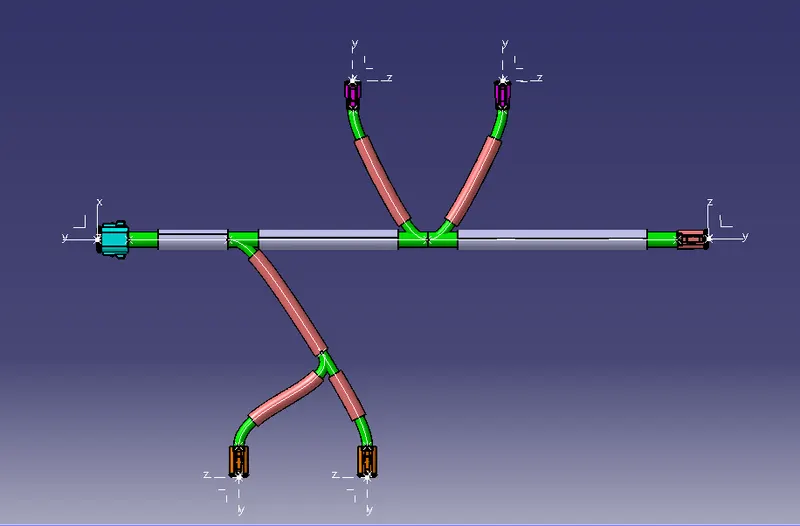
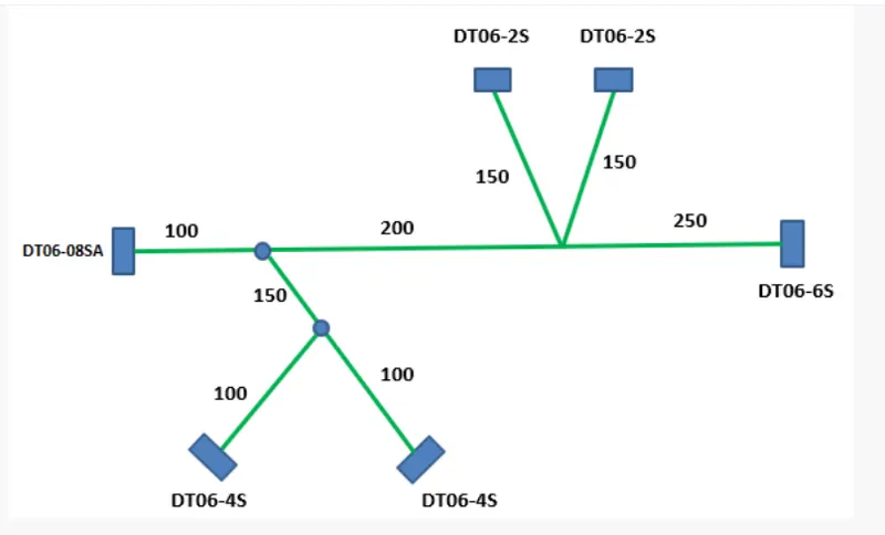
- To route the given harness layout in electrical workbench. Make assumptions for harness bundle diameters.
- Download the connector CAD data whose series number is mentioned in the given harness layout and use them in the wiring harness routing.
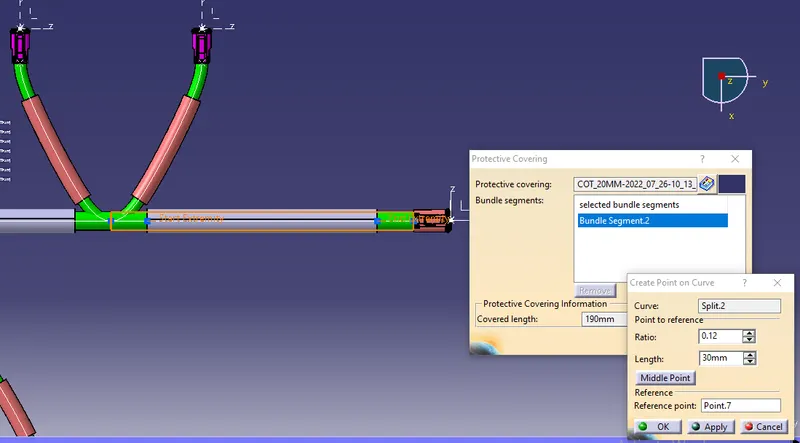
- To Add protective covering on all branches connected to DT06-2S & DT06-4S connectors and keep end extremity at 30mm( from connectors end).
Following are connectors that we will be using in our wiring harness routing and installation.
- DT06-4S
- DT06-6S
- DT06-2S
- DT06-08SA
WIRING HARNESS LAYOUT:
WIRING HARNESS ASSEMBLY STRUCTURE-CONNECTOR DEFINITION:
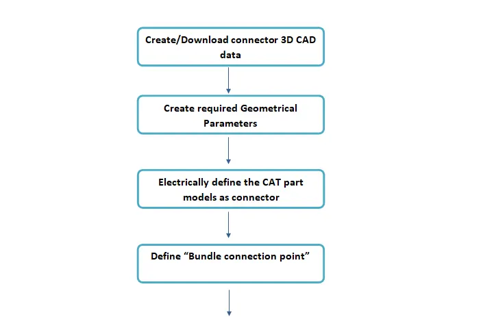

DEFINING CAT PART AS CONNECTORS:
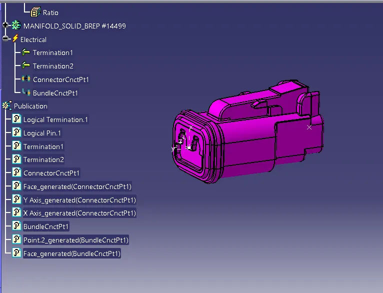
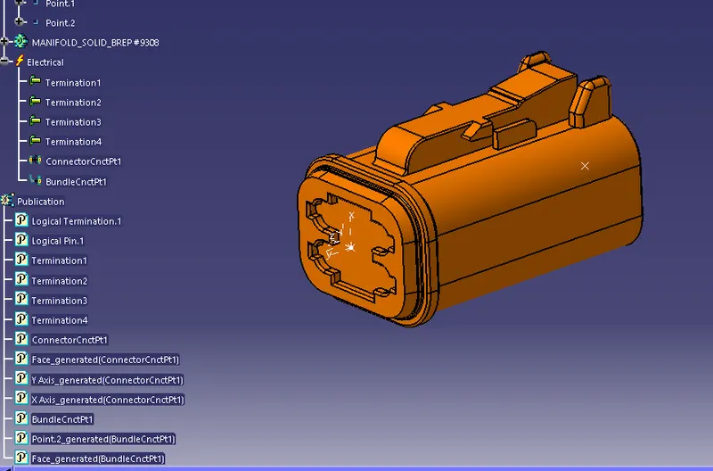
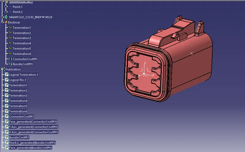
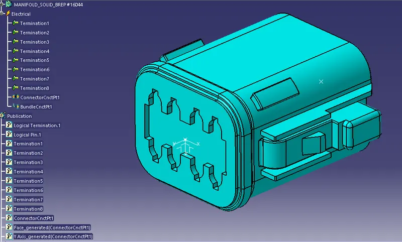
PREPARATION OF HARNESS ASSEMBLY
As we are done with Wiring harness component designs, now our second task would be to prepare Product assembly for given harness.
Wiring harness Product assembly contains-
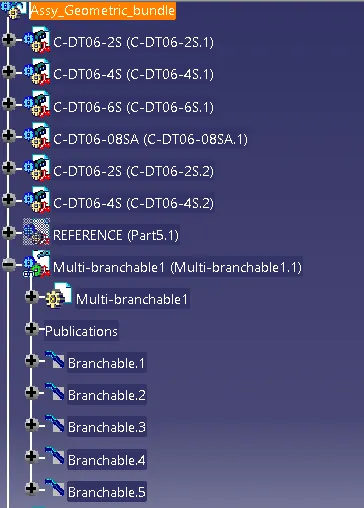
The Harness Context Assembly- This is the top level product file that contains Geometrical Bundle/Assembly and the wire harness electrical bundle.
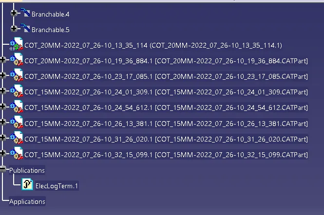
Geometrical Bundle- This sub level product file is the wire harness product that contains all of the harness components i.e clips, supports, connectors, splices, grommetsm annotations and actual physical bundle segments and branches.
Electrical Bundle- This sub level product file contains all of the electrical circuit information.
WIRING HARNESS ASSEMBLY STRUCTURE
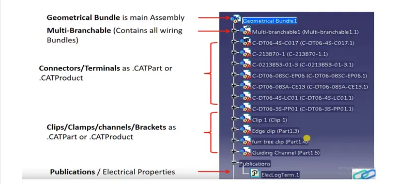
WIRING HARNESS ASSEMBLY PROCESS:
- Before adding the wiring harness components to the wiring harness assembly make sure all the wiring harness components are electrically defined.
- After adding all the electrically defined components into the wiring harness assembly we need to convert this mechanical assembly into electrical assembly.In order to convert that we'll switch to Electric harness assembly workbench.
- In electric harness assembly workbench we need to select "Geometric Bundle" command and then we have to click to the part assembly which named as geometrical bundle assembly.
- We can verify whether the product file is converted into electrical product or not by checking the icon of the product file, if electrical symbol appears on it, then we can say that the product file is converted.
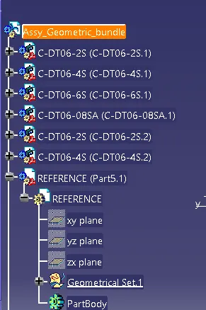
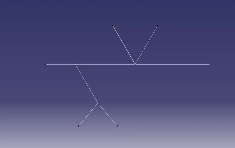
- Now in order to position all the connectors as per given layout we need to create a sketch in another part file, this sketch will be having the same dimensions as shown in the wiring harness layout.
- We will add this part file containing the reference sketch into the geometrical bunddle and we'll name it as "Reference" because we'll be using this part file to position the connectors.
- We can take help of "snap" or "manipulation" command available in the part assembly workbench to locate or position all the connectors to their respective positions using the reference sketch.

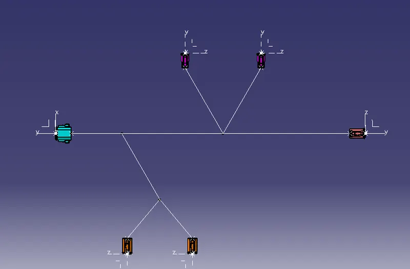
DEFINING THE WIRE HARNESS ROUTING
Part-1 Creating simple wire harness bundle segments
part-2 creating harness multiple branches
Pre-requisites:
- Geometrical bundle assembly is completed.
- All components are placed at desired location
- All types of Electrical Connectors/Constraints are defined.
- Background Geometry datais available & in Geometrical bundle context assembly.
- All clips/clamps/channels are placed at desired locations.
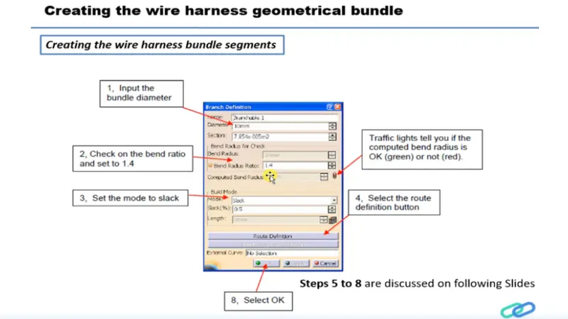
CREATING THE WIRE HARNESS GEOMETRICAL BUNDLE
Creating the wire harness bundle segments
- Switch to the electrical harness assembly workbench.
- Ensure that you have your harness geometrical bundle highlighted.
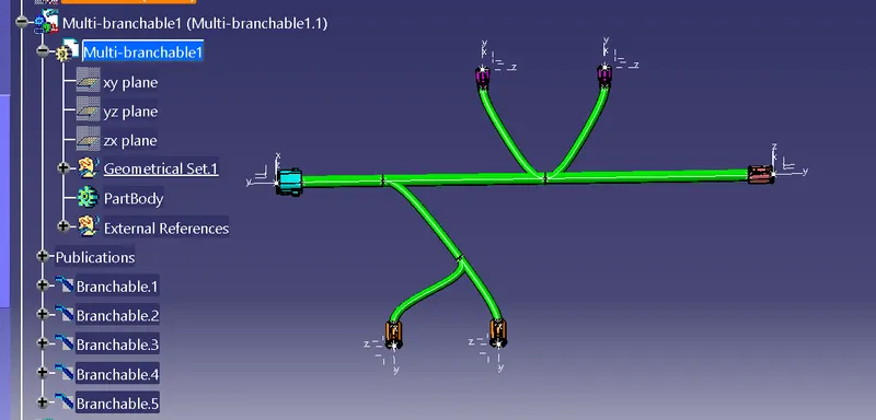
- Select the create multi-branchable document icon.
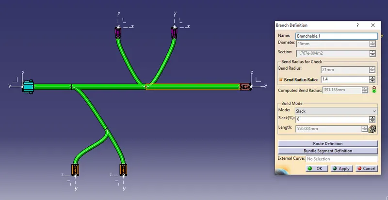
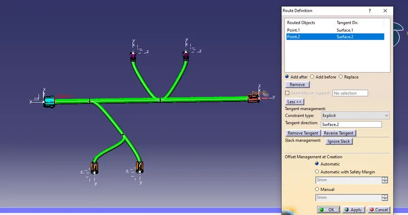
- In the branch definition box input all the required Parameters.
- Ensure that the bend radius ratio is set to 1.4 or greater than 1.5 and that the check box is on.
- Ensure that the build mode is set to slack.