Fender Design Challenge
FENDER DESIGN USING CATIA V5
OBJECTIVE
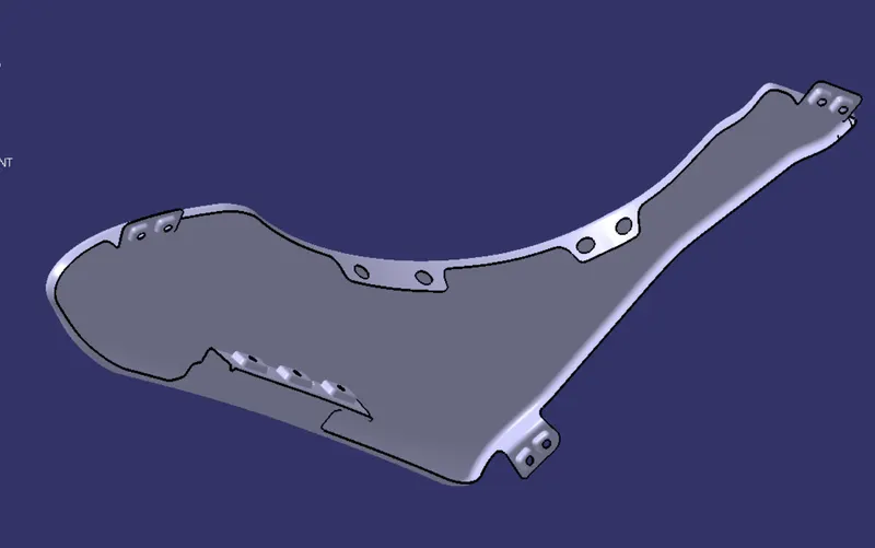
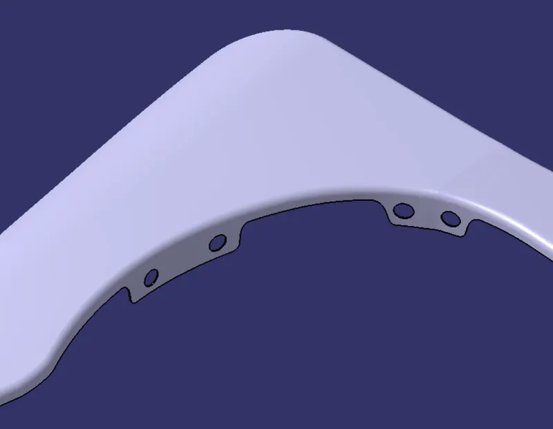
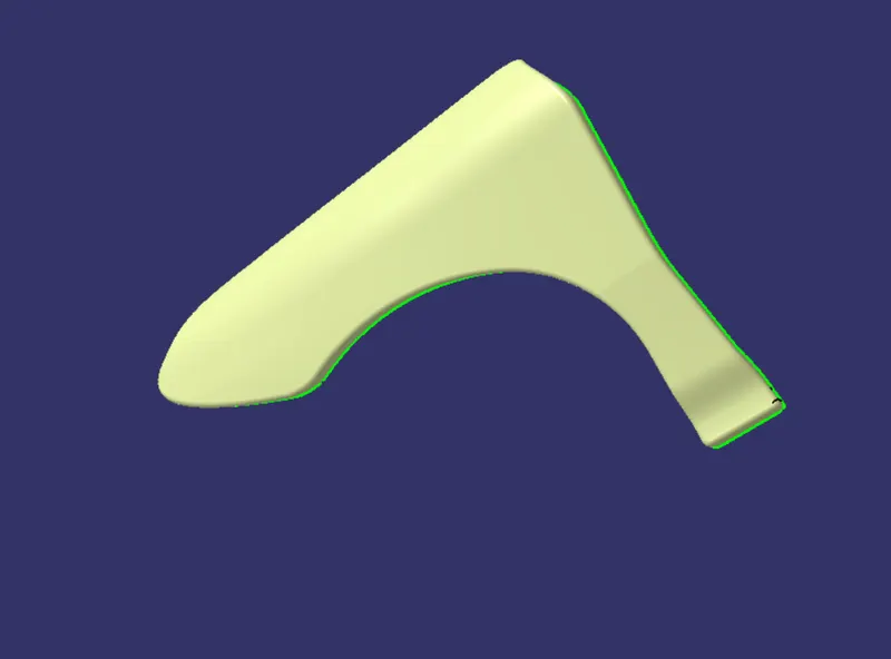
- To design fender from the given input (class A surface) by modifying the class A surface in generative shape design workbench of Catia V5 in order to design mounting features of the fender.
- To develope drip portion of the front fender using master section data given to us as an input.
- To develop other mounting features like sill, Bumper, Baffle(splash), and A-pillar mount.
INTRODUCTION
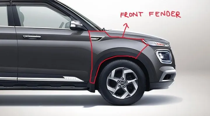
FENDER :
Fender is a BiW component which is basically a sheet metal frame that is mounted over the wheels of the automobile, its primary function is to prevent sand, mud, stones, liquid and other road spray from being thrown into the air or enigine compartment.
By doing this it serves basically two main purposes, first one is to prevent the padesterian from getting hit by the stones hurled by the car wheel. The second purpose it serves by preventing any damage to the engine or other components located inside the engine compartment from stones or mud hurled by the car wheels.
When vehicle is moving tyres pick up stones and other hurl them in all directions. Fenders are basically present to prevent any injuries to pedesterians and contains the motion of these particles.
TYPES OF FENDER
FULL BUMPER TYPE: Full bumper type fenders were mostly used in traditional or old passenger vehicles, they usually have wider frames reaching upto the front lamps and even in some passenger car models fender and bumper comes as a single unit. Since full bumper type fenders are made out of large size blanks therefore a lot of material wastage takes place which costs the car manufacturer a lot during the mass production, in addition to that it also increases the overall weight of the vehicle which affects the performance of the vehicle.
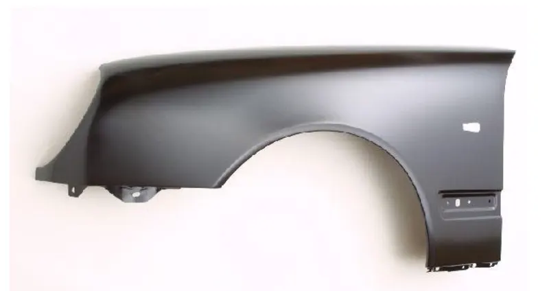
HALF BUMPER TYPE : Half type bumper is the type of fender which is being used in almost all the passenger cars now a days, with the advancement in car designs we adopted the half bumper type fender design because it requires much lesser size of blank than the full bumper type fender. It is less costly and reduces the overall weight of the car which leads to a better car performance.
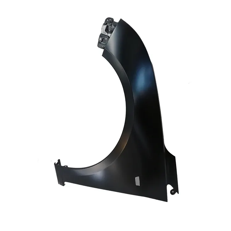
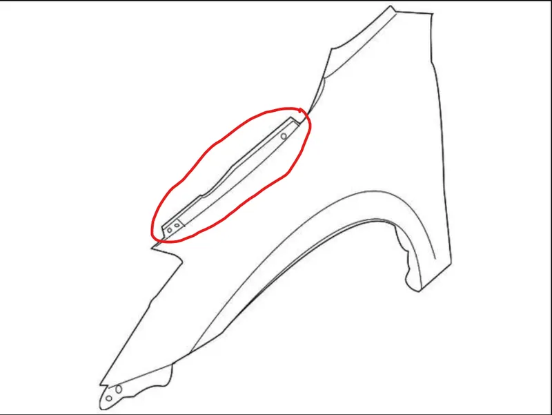
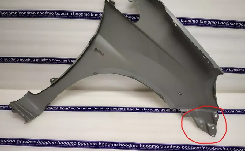
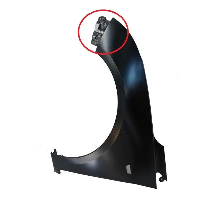
FENDER MOUNTING POINTS:
A-PILLAR MOUNT
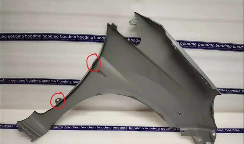
SILL
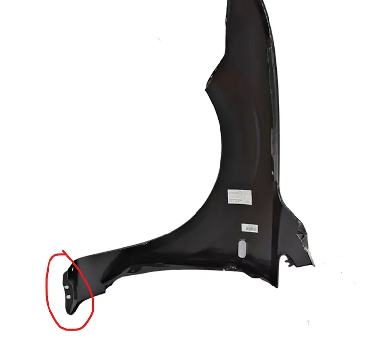
BAFFLE MOUNT
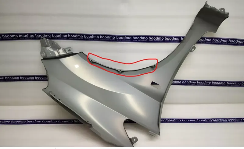
DRIP MOUNT
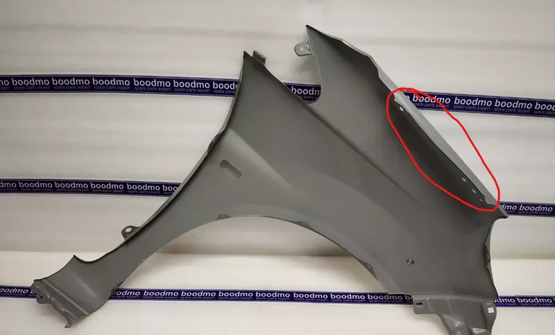
BUMPER MOUNT
DESIGNING METHODOLODY:
IMPROVING CLASS A SURFACE
The class A surface we got as an input to design fender along with all the mounting points needs to be improved because the class A surface is just an aesthetic surface which do not contains the engineering features.
Improvement of class A surface is also done to remove unwanted patches which can affect the manufacturing of the component, so we need to remove such patches by recreat them without any flaws.
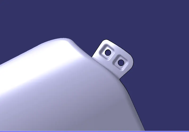
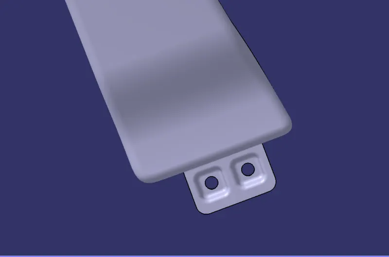
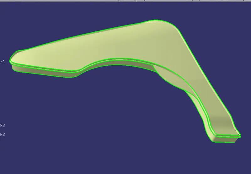
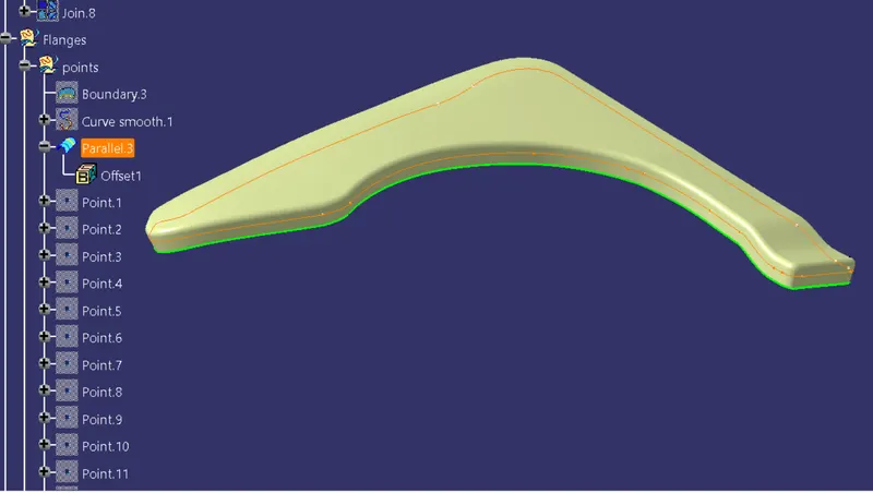
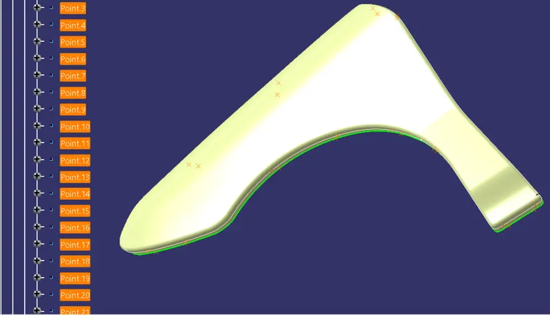
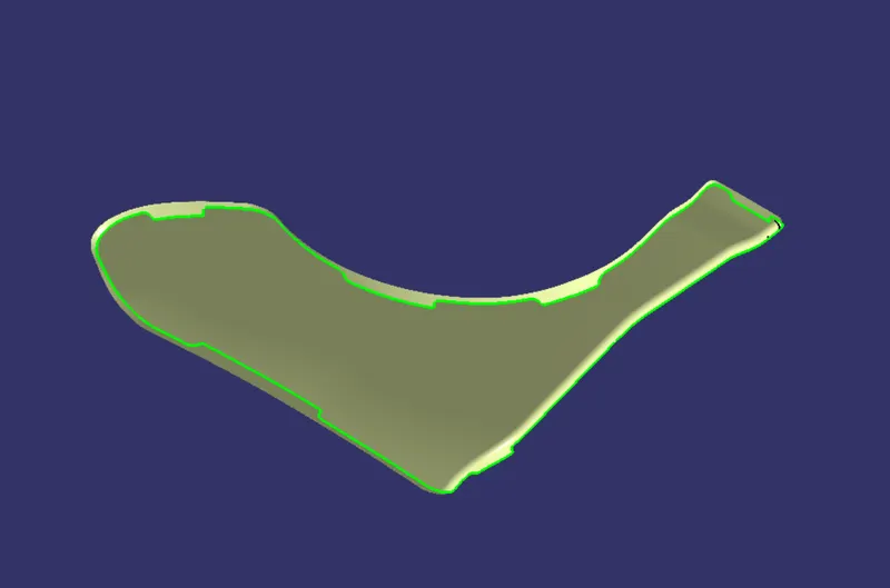
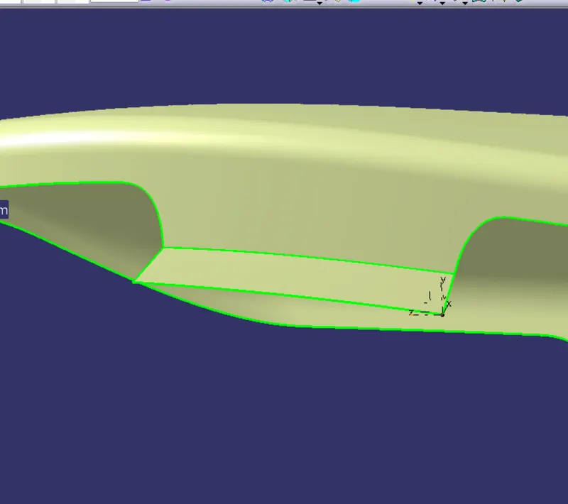
To create the mounting areas we'll first create points on the boundary as well as on the parallel curve made with a constant value of 10mm from the boundary of the fender. All these points will be created on the locations where we want to create mounts. These points will be representing the edge corners of the flanges that we'll make afterwards.
We'll join each point in the boundary line of the fender with the corresponding point on the parallel curve with the help of curves, all these curves will be representing the edges of the flanges of the mounting areas.
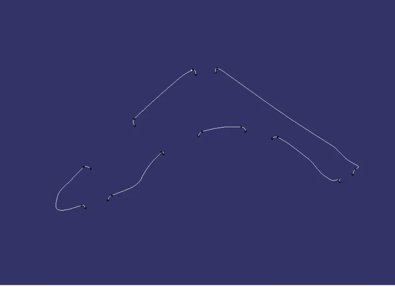
After that we'll split the parallel curve with the curves that we made in the previous step, we'll split it in such a manner so that we get the curves representing the edges of the gaps between the mounting flanges.
We'll join all such curves and convert them in a single entity, one thing we have to make sure that while joining the curves we need to uncheck the connectivity check box.
finally we'll split the fender surface with recently made join as a cutting tool, the resulting fender surface we'll get will have required base flanges for all the mounting points.
DESIGN CONSIDERATION FOR DRIP AREA:
DRIP is the mounting area on the fender which is used to mount the fender body on the BiW frame of the engine compartment.
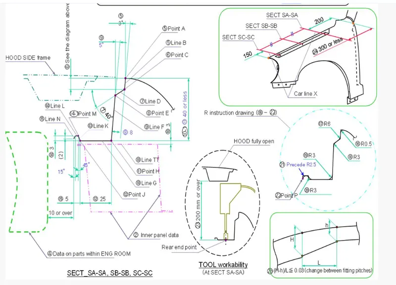
There are some engineering aspects with regard to the drip area design, as we can see in the master section a minimum angle of 3 degrees is given to the drip side walls, this is because a straight vertical wall is not feasible to manufacture and it would also lead to gap and flush issues.
Since these side walls of the drip area are inclined to an angle of 3 degree from the vertical plane, this inclination would lead to the exposure of the mounting fastners and other engineering features which should'nt be exposed to the customer, so to resolve this problem we design another wall connecting the upper side wall and lower side wall having a minimum length of 8mm and an inclination of 40 degrees from the horizontal plane. This wall prevents the inside engineering features to be exposed or to be seen by the cutomer.
Hood side drip depth must be 40mm or less as the maximum productivity is achieved at the depth of 40mm. If depth exceeds 40mm, rigidity bead is to provided, also forming is not feasible if depth exceeds 60mm due to wrinkling and spring back effect.
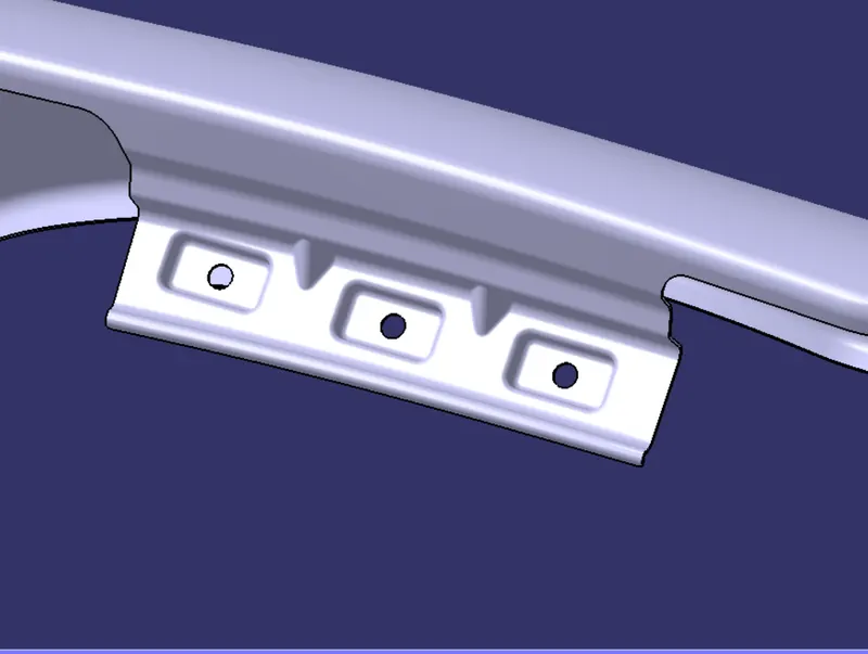
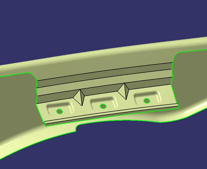
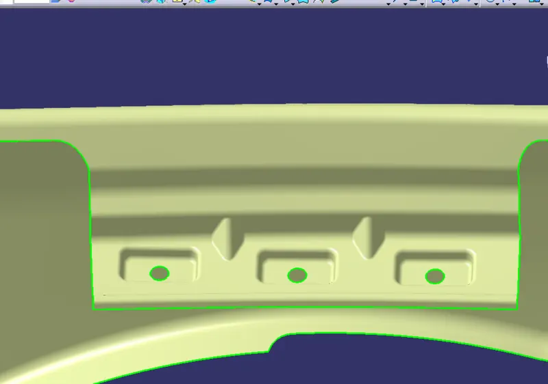
A wedge shaped emboss is provided at the end of the flat mounting surface of the drip in order to provide strength and rigidity to that portion.
A space of at least 10mm must be there between the innermost point of the drip and the engine compartment.
MASTER SECTION FOR DRIP
CREATION OF DRIP AREA
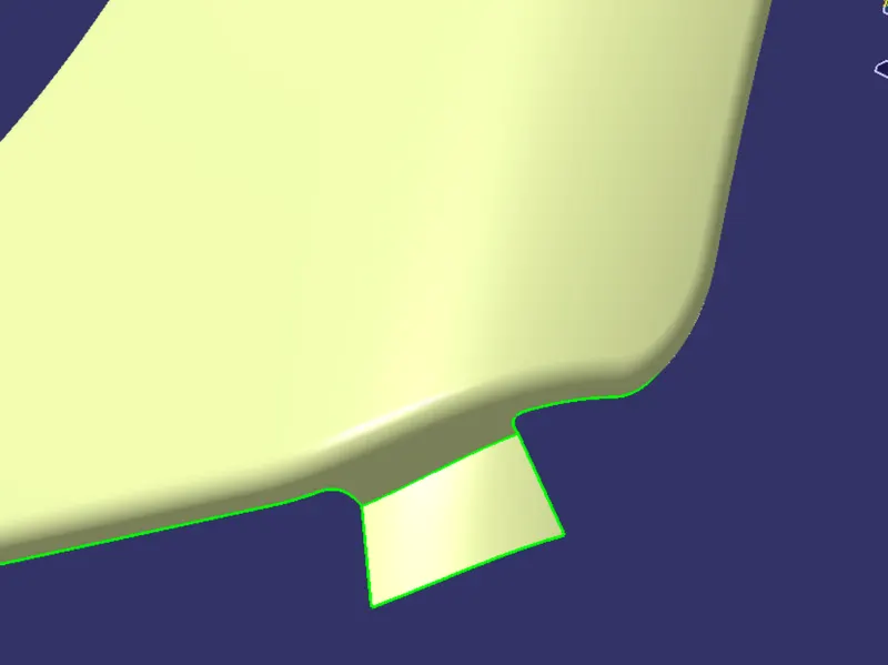
Taking the reference from the master section create the side walls of the drip, here we can use sweep command with "with reference surface"option and try to give draft values as similar as shown in the master section. we have been giving the draft value by the personal judgment because the class A surface given to us is not oriented along any plane.
Similarly take reference from the master section and create all the surfaces in the similar manner using the sweep command.
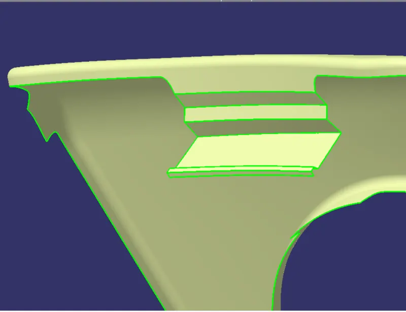
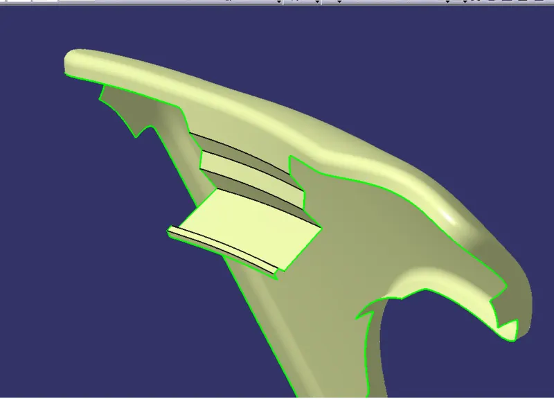
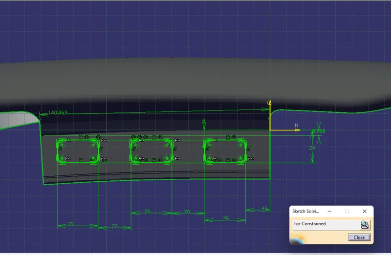
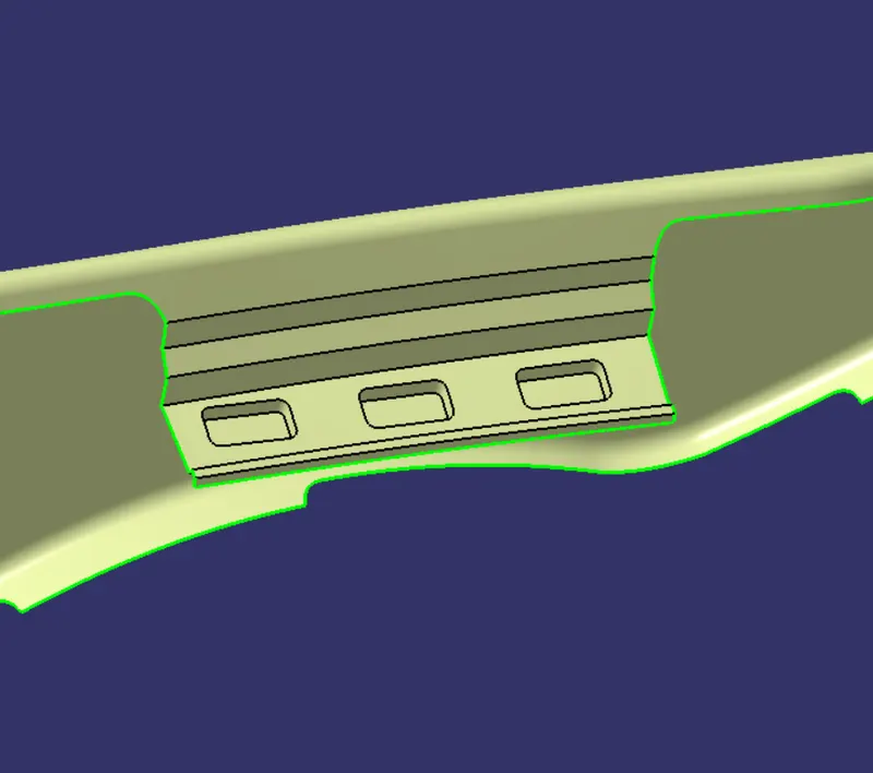
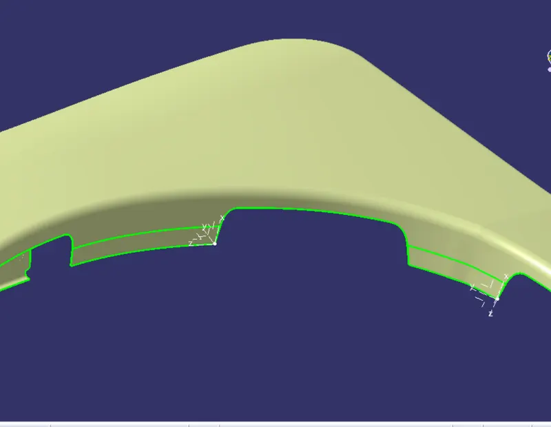
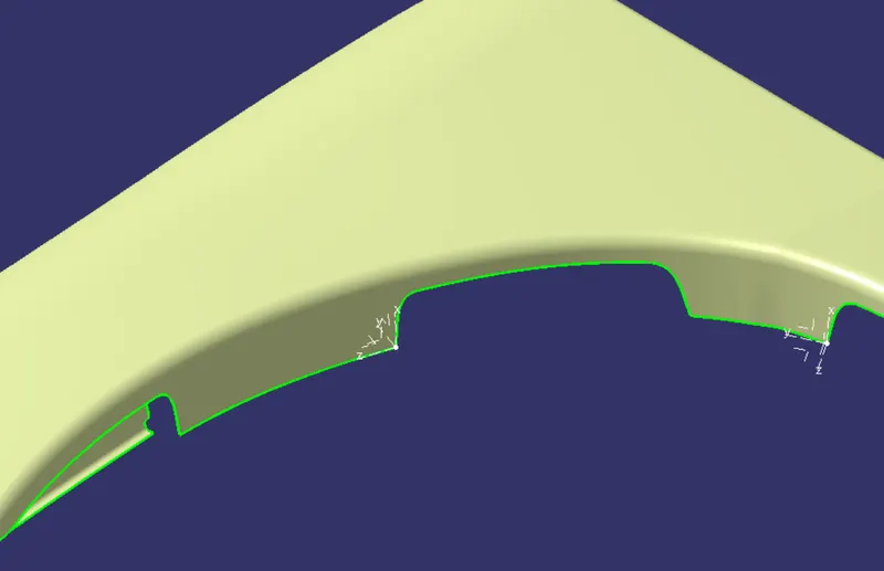
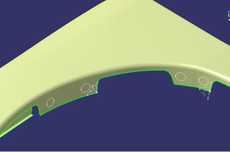
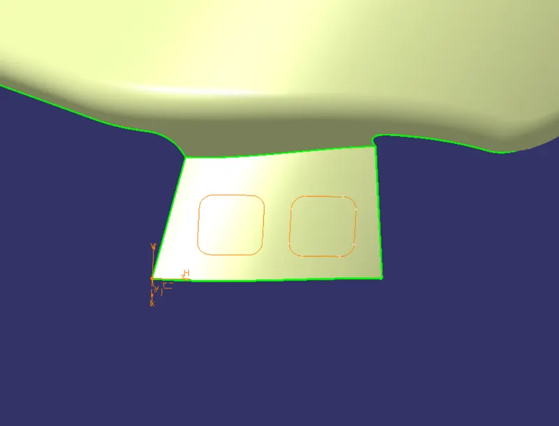
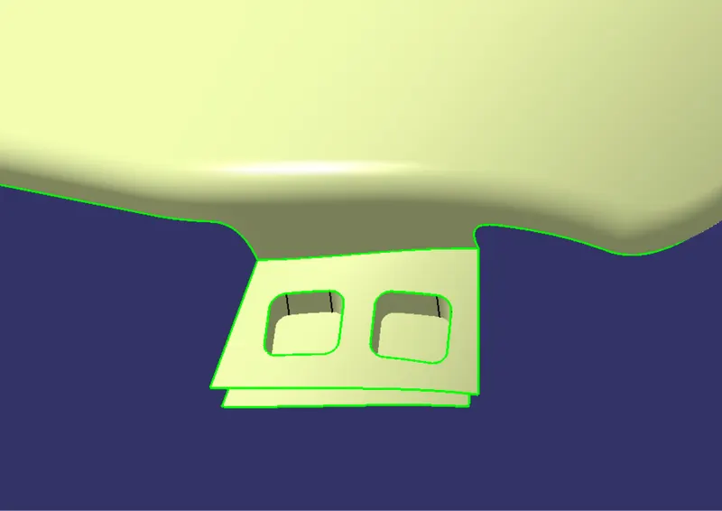
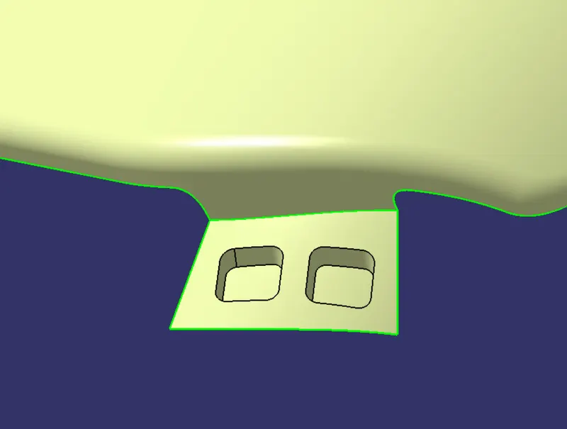
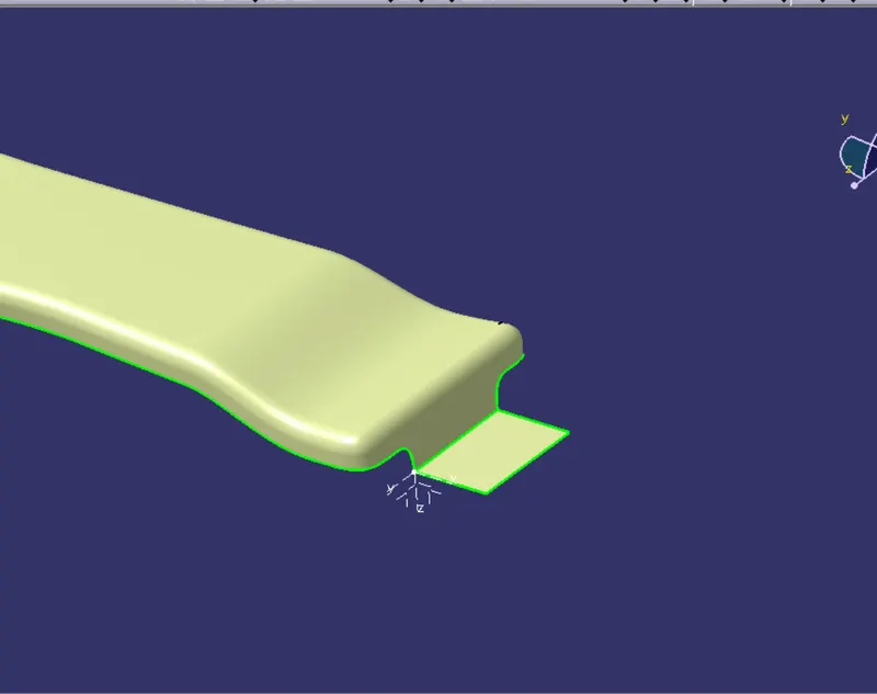
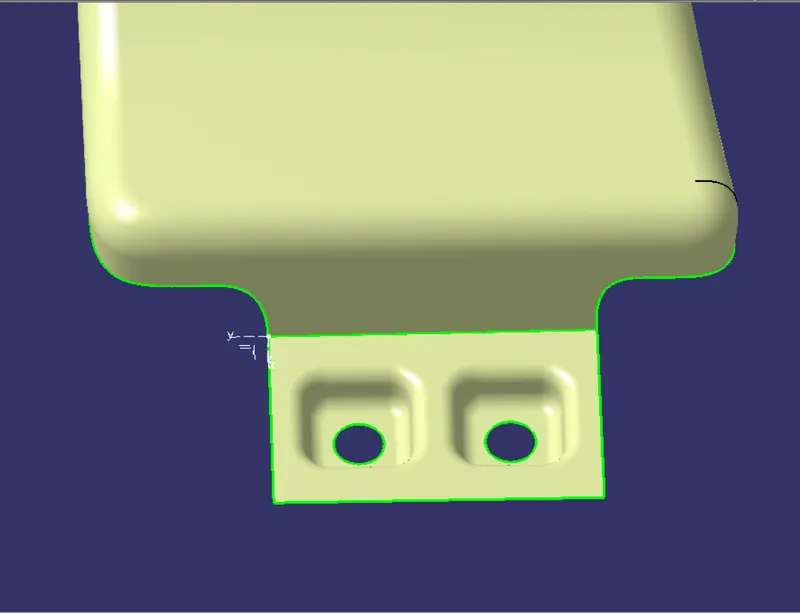
Insert the axis system on of the corners of the flat surface of the drip in order to create sketch over that surface, the sketch is being made to create rectangular cut sections on the flat surface.
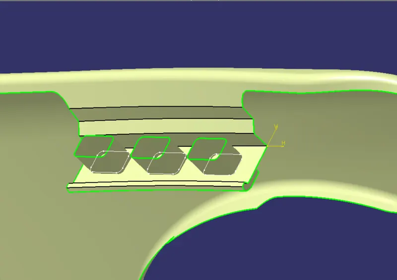
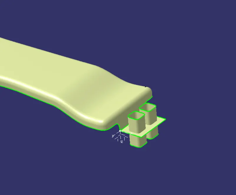
Extrude the sketches in the direction normal to the flat surface and split the surface using with the rectangular extruded surfaces as a cutting tool.
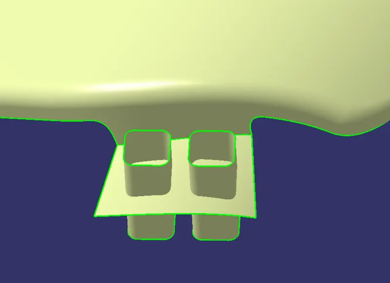
Now create another sweep by choosing the profile as the extracts of the cut sections and taking draft direction as the normal axis to the flat surface, after this join the sweeps with flat surface.
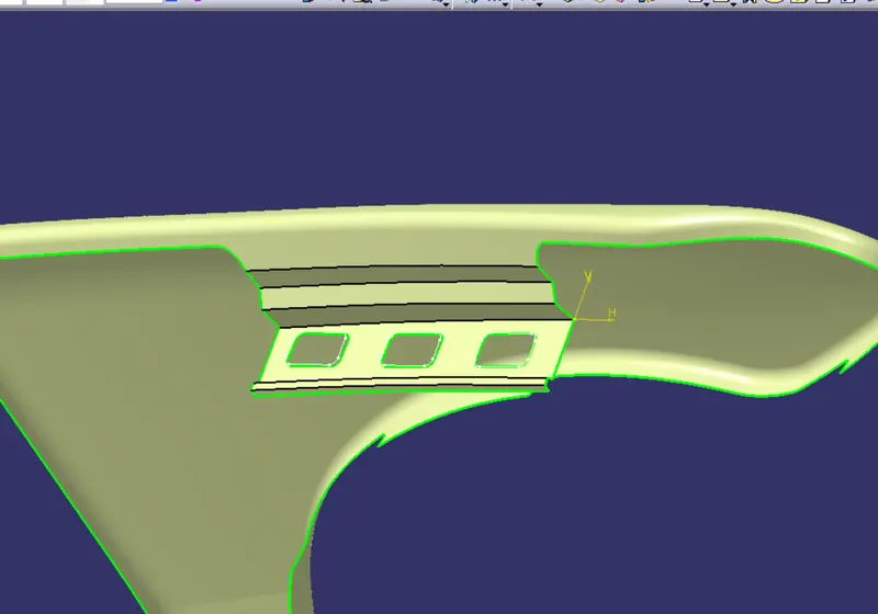
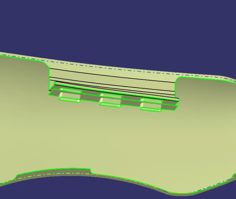
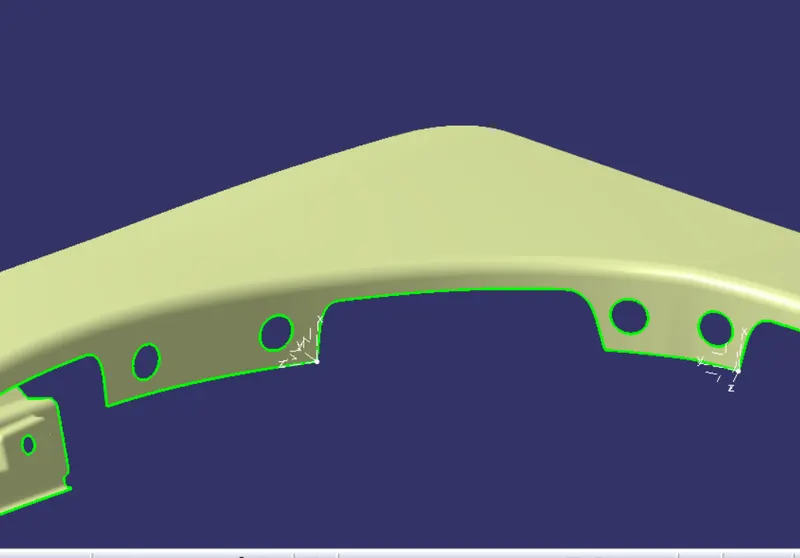
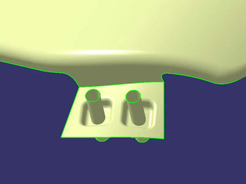
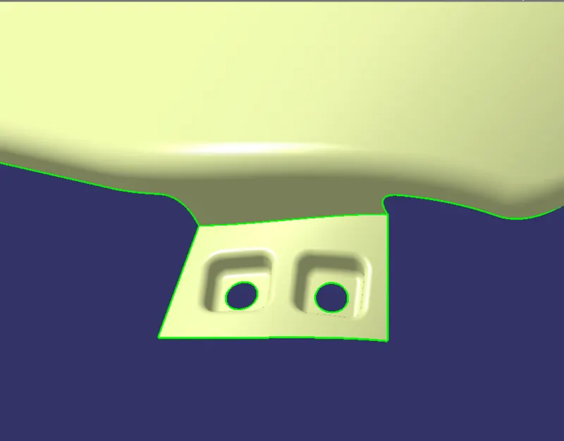
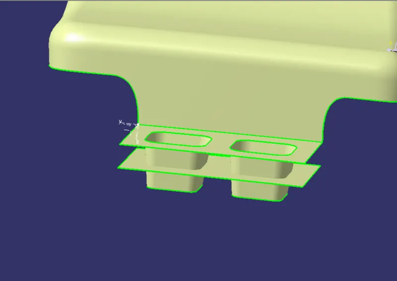
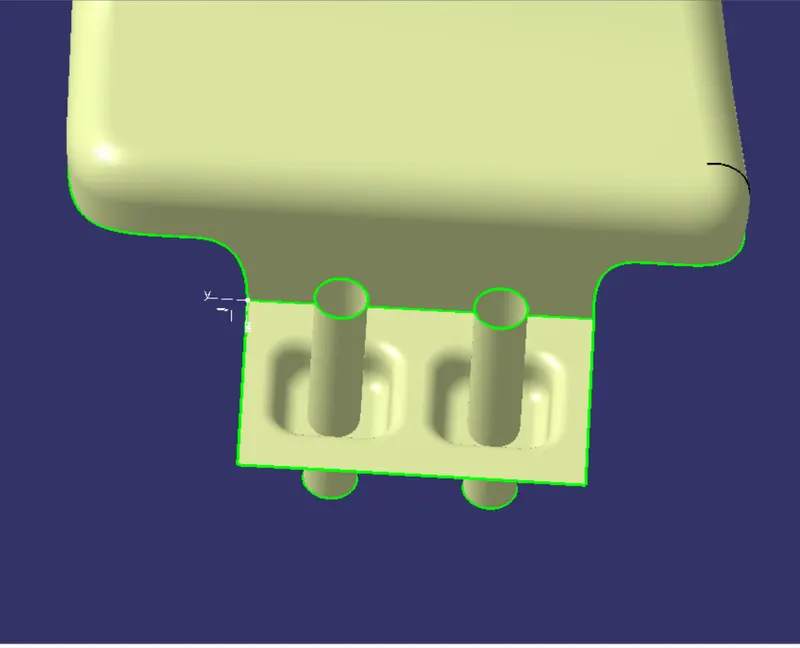
Create an offset surface out of the flat surface of drip with an offset value of 5mm in the downward direction and trim this surface with the previously made join. The resulting surface will the embosses for the mounting fasterners on the drip.
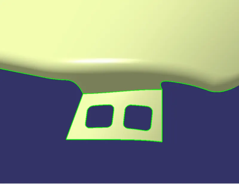
We can create the holes on the embosses in the similar manner as that of the rectangular cut outs we made earlier.
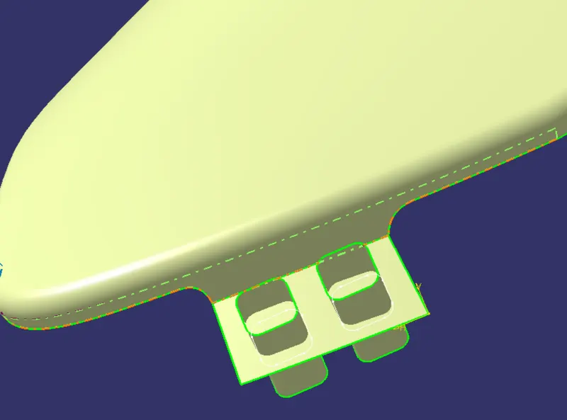
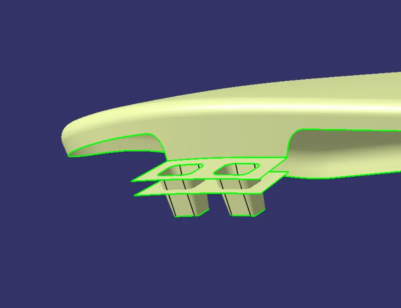
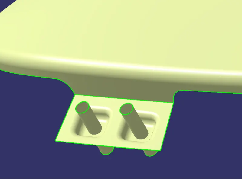
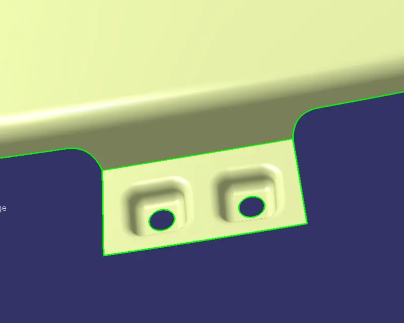
CREATION OF BUMPER SIDE MOUNT:
CREATION OF BAFFLE :
CREATION OF A PILLAR MOUNT:
CREATION OF SILL AREA:
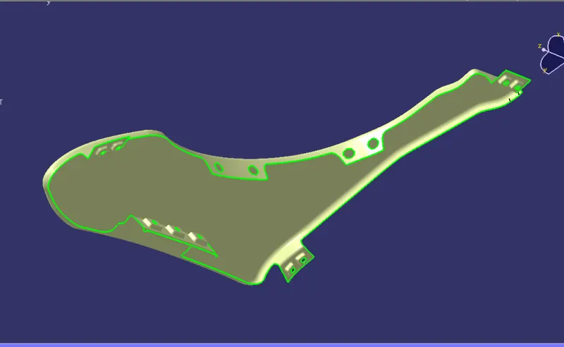
FENDER PART MODEL: