Week 8 - Challenge 1 - Draft Analysis on a Fan Cover
DRAFT ANALYSIS REPORT
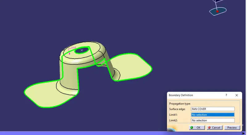
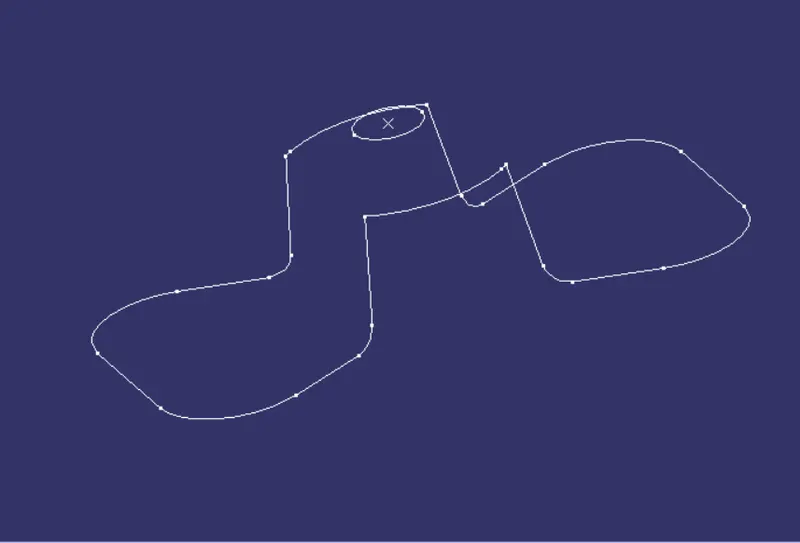
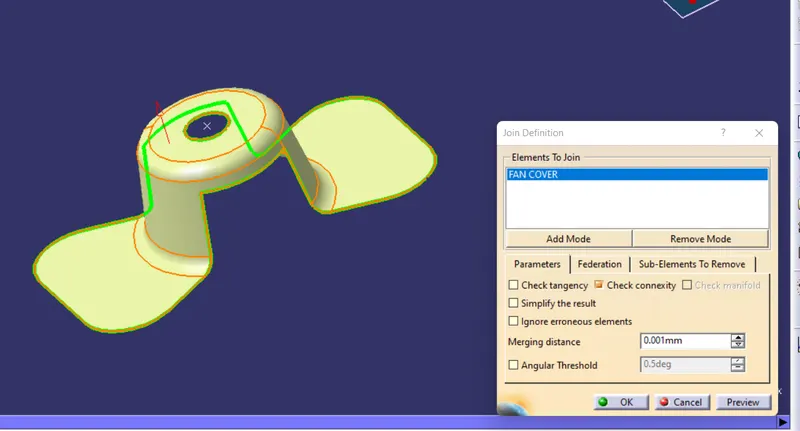
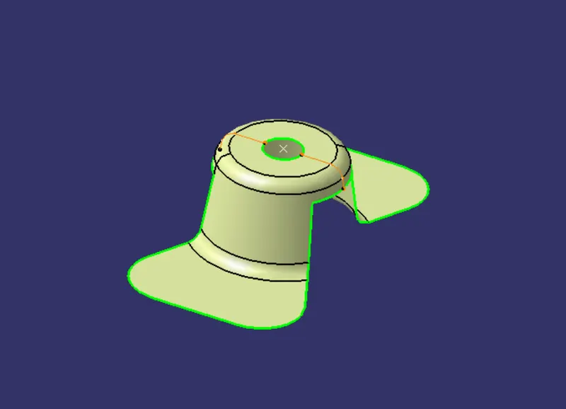
STEP1: Ensure the class A surface is properly joined from all the edges and there is no gap or discontinuity between them. We can check it by two using BOUNDARY and JOIN command.
CHECKING THROUGH BOUNDARY COMMAND:
CHECKING THROUGH JOIN COMMAND:
STEP2: Analysing the model by manually interospecting for determining the most suitable tooling axis direction.
- on analysing the model in isometric view we can clearly see a hole on the top surface of the model.
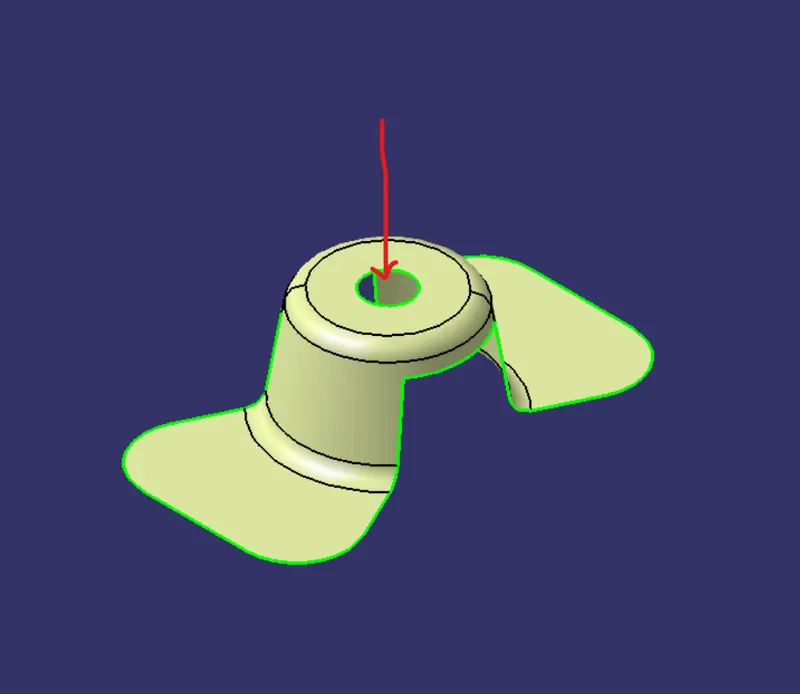
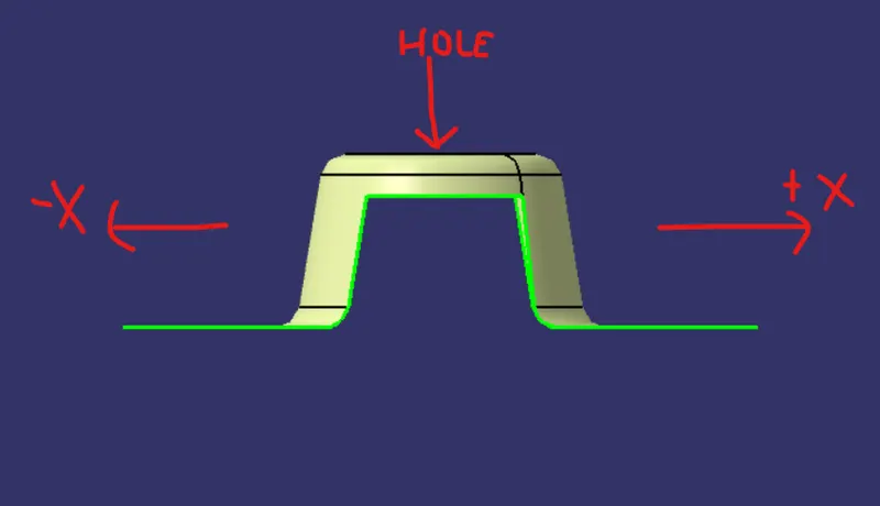
- From the front view of the model we can clearly see that the top surface hole can not be cleared in X direction.
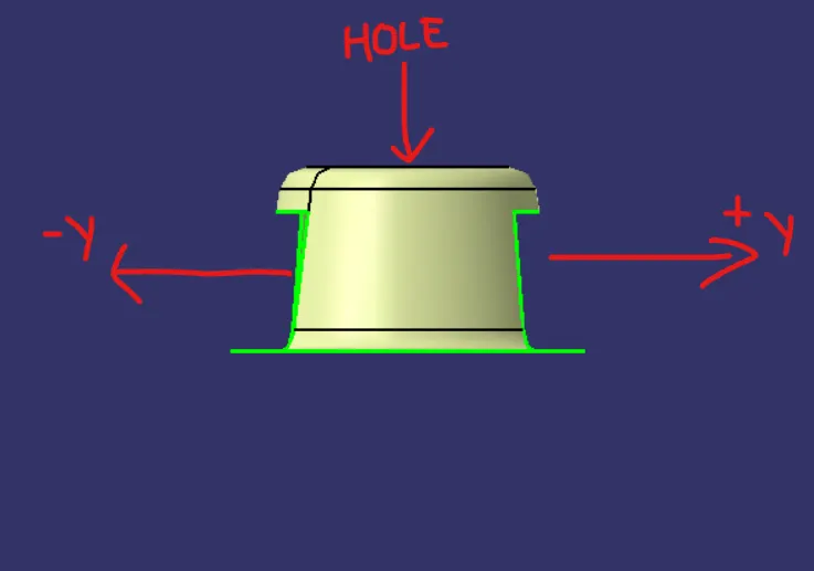
- Similarly from the side view of the model we can again see that the same hole can not be cleared in y direction.
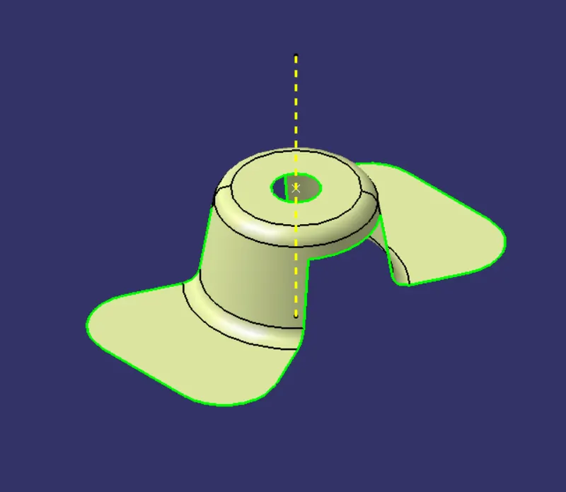
- But if we look from top view or isometric view we can analyse that the hole can be cleared through z direction.

- since we saw that the hole is clearly visible from the top view so we choose z direction as the direction of tooling axis, so we will create a dummy axis along this direction as shown in the figure below.
STEP3: FINDING OUT THE REAL TOOLING AXIS USING BISECTING METHOD.
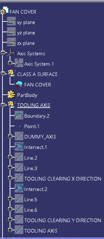
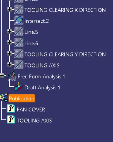
- Firstly we will insert an axis system on the centre of the hole and project the outer surface boundary of the model in z-x plane by using the intersect command in which we will intersect the zx plane of the axis system with the fan cover. From this we will get surface boundary.
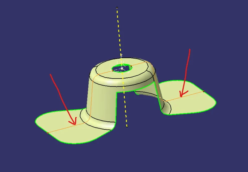
- After getting the required lines we have to see which surface will create problem during tooling process and make a line along that surface, similarly we will create another line along same surface on the other side.
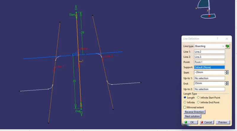
- Then we will create a bisecting line using the two lines drawn earlier and taking the center point of the hole as the support option as a result of which we will get the tooling axis clearing X direction.
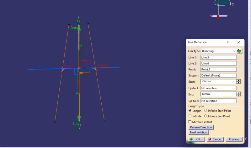
- In the similar manner we will find out the tooling axis clearing Y direction.
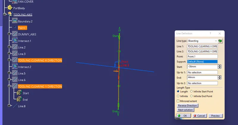
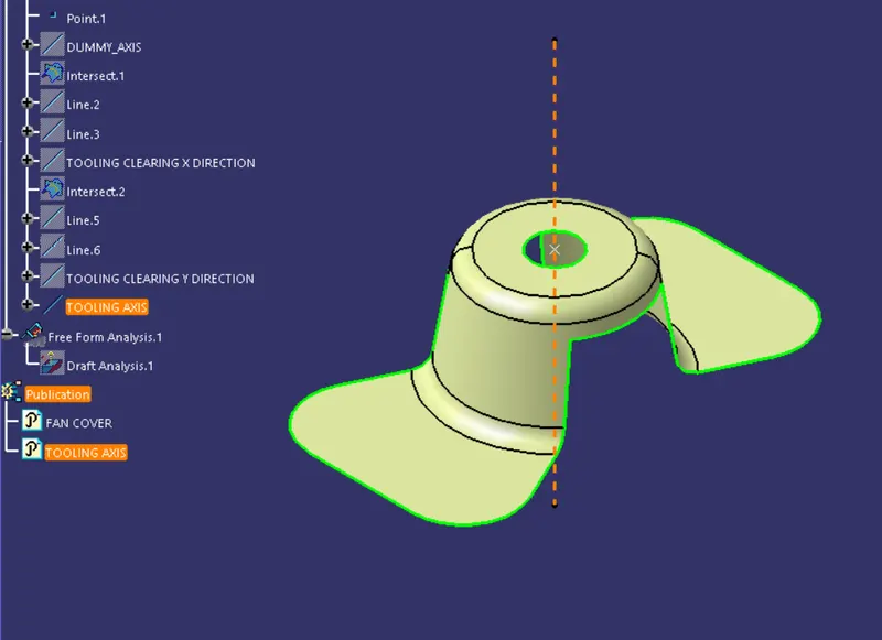
- Finally we will create a line using bisecting method by taking both the tooling line clearing X and Y direction. This line will be called as the main tooling axis.
STEP4: DRAFT ANALYSIS
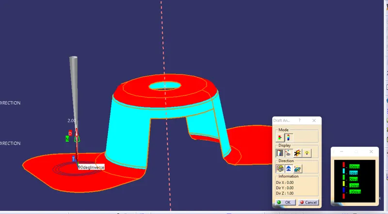
- Draft Analysis gives us the complete information of the draft values given to a particular model on its different faces or surfaces.
- To initiate draft analysis go to insert>analysis>feature draft analysis.
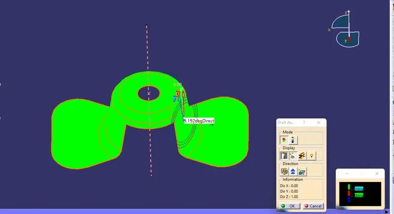
- Click on the compass icon and align it with the tooling axis of the model.
- Click on quick analysis mode and we will get the results.
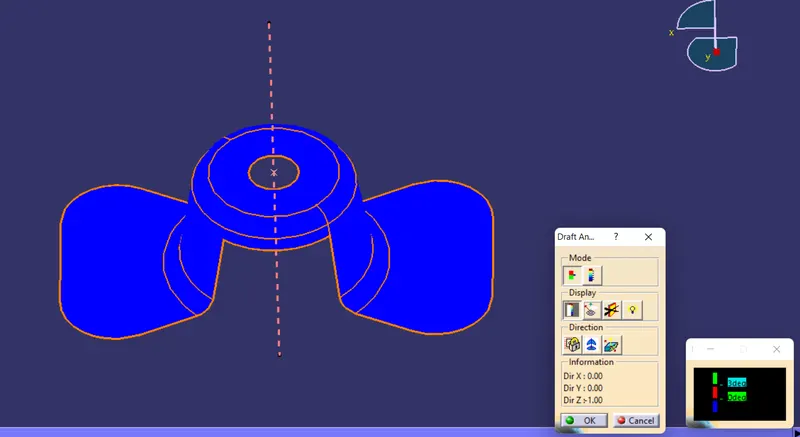
- If the clour of the model surface appears blue it means the draft direction is reversed, to change it click on inverse draft direction.
- For getting complete analysis we can click on full analysis mode.