Week 8 - Challenge 5 - Core & Cavity Design
CORE AND CAVITY DESIGN FOR THE SWITCH BEZEL MODEL
OBJECTIVE:
- To create tooling axis for the switch bezel model.
- To design core and cavity for the switch bezel model.
DESIGNING METHODOLOGY:
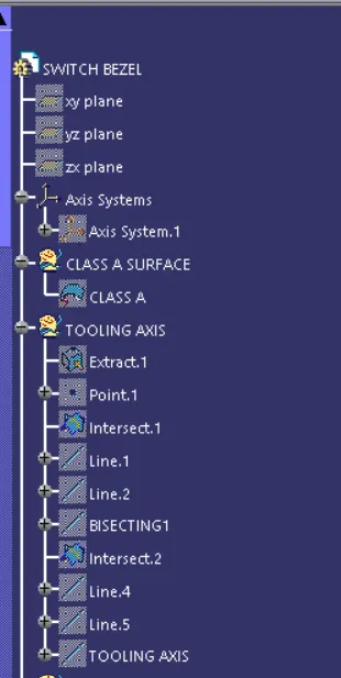
CREATION OF TOOLING AXIS
- The first thing to create the tooling axis is to analyse the class A surface through visual inspection.
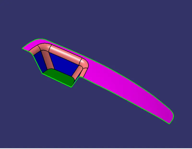
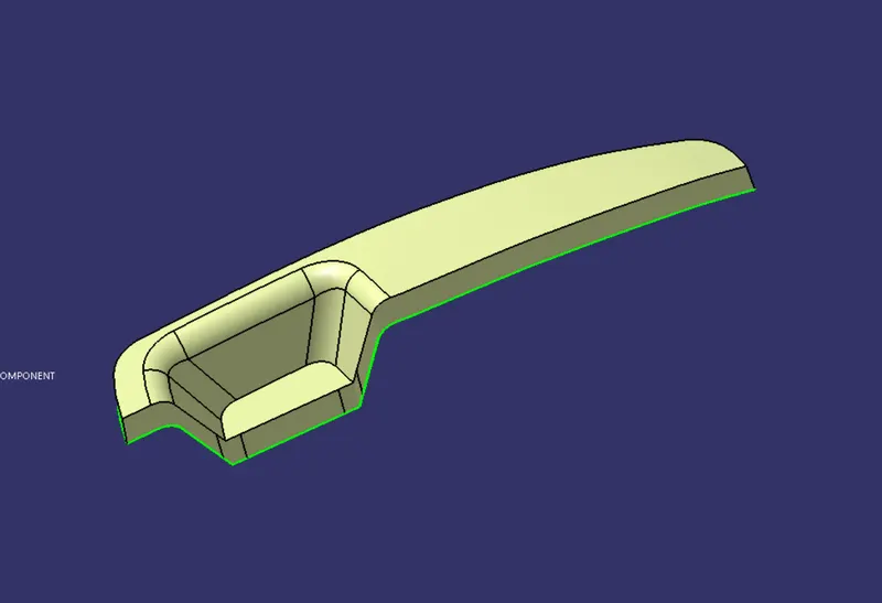
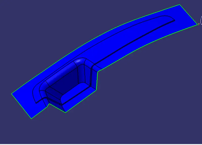
- When we see the class A surface in isometric view we can clearly see that it consists of basically two types of surfaces one is a nearly flat surface and the other one is forming a kind of pocket into the flat one.
- The flat surface is not going to create any problem during the tooling operation but the second one which is in a shape of a pocket can create problem during tooling.
- So to clear the pocket walls we will first extract and untrim the base surface of the pocket and then insert a point in the middle of the base surface, after that we will insert the axis system on that point.
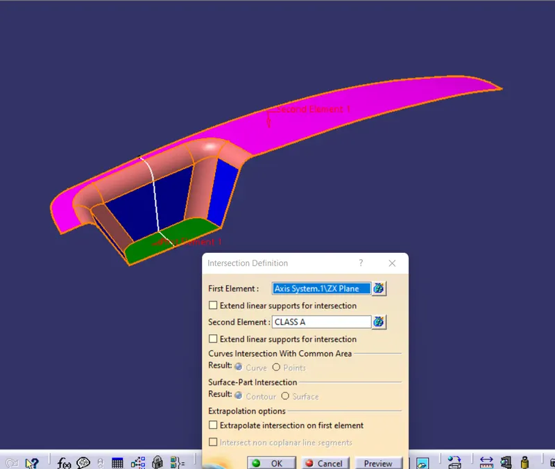
- In order the to clear the side walls of the pocket we will intersect the YZ plane of the axis system with the class A surface with the help of intersect command. After that we will create lines along the side walls with the help of the obtained intersection curve.
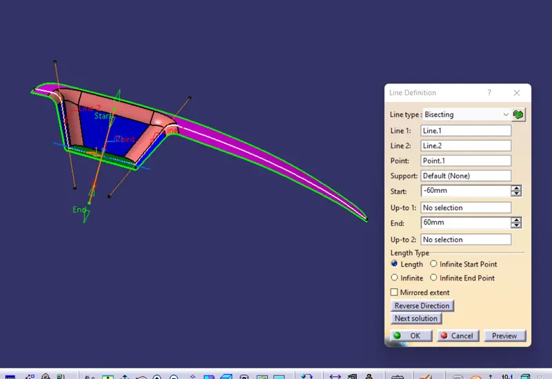
- After drawing these two lines we will create another line which will bisect the earlier drawn two lines, we will use bisecting line option to create this line.
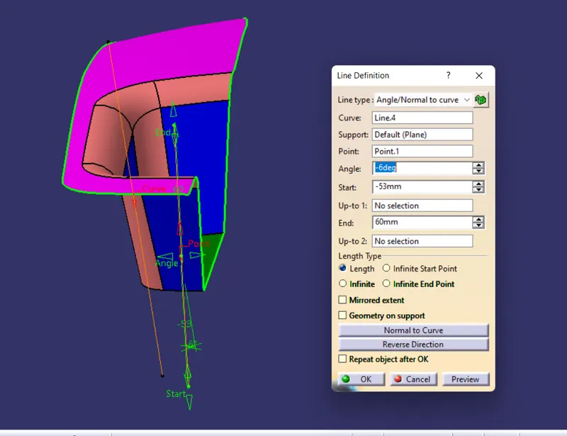
- To clear the front face or wall of the pocket we'll again use intersect command to intersect the ZX plane with class A surface, from here we'll get an intersection curve with the help of which we will create a line along the front wall of the pocket. we will create a line which be at an angle of 6 degrees to the previous line and passing through the point at middle of the base wall.
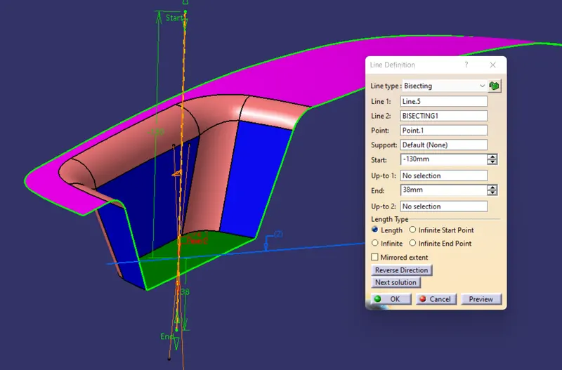
- Finally we'll create a final line which will bisect both tooling lines clearing X and Y directions and this line will be called as the main tooling line.
PARTING SURFACE CREATION
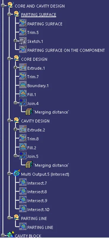
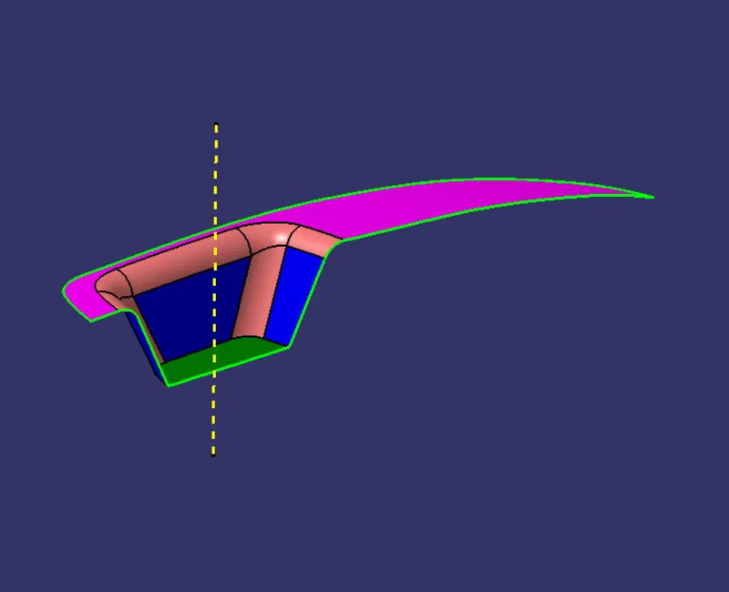
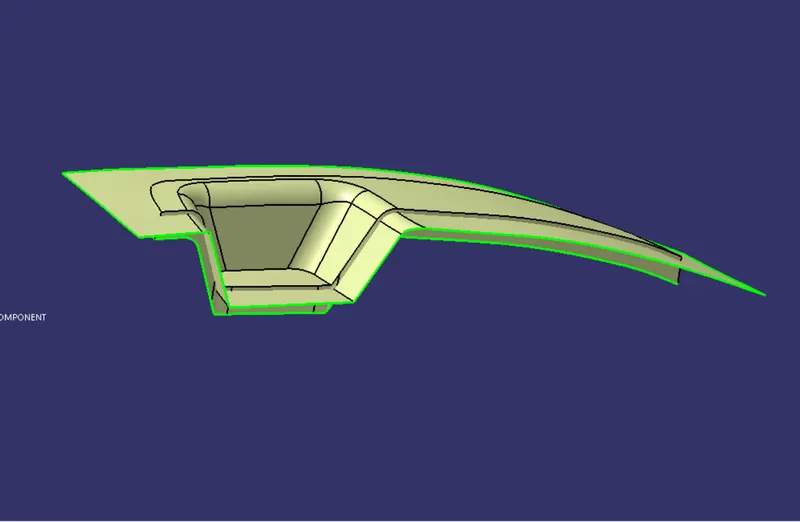
- Take class A and class C surfaces and join them using join command.
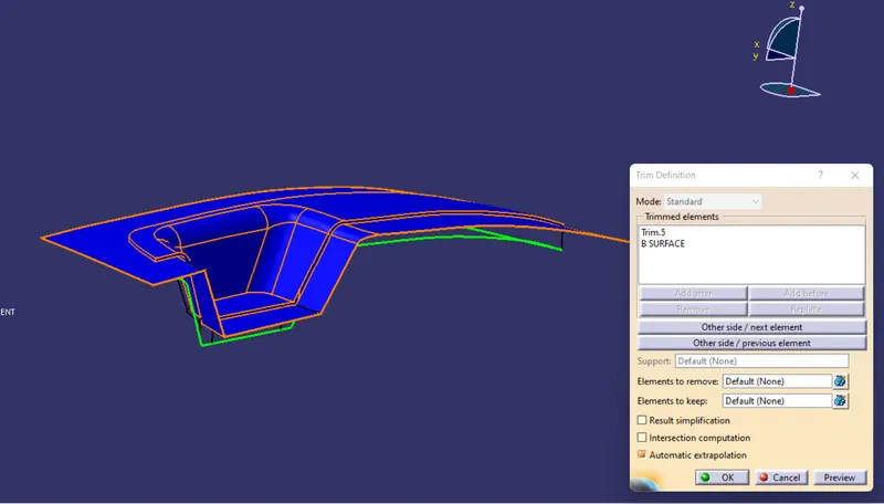
- Trim the resulting join of class A and class C surface with class B surface using trim command.
- The resulting trim will be called as the parting surface.
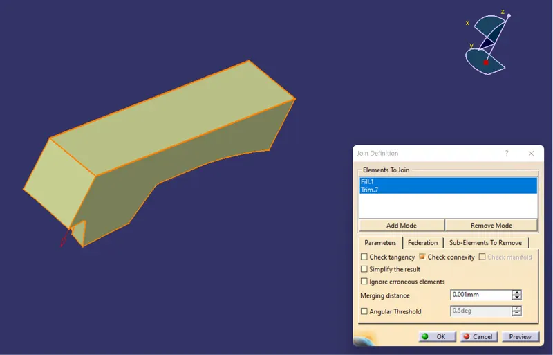
DESIGNING OF CORE
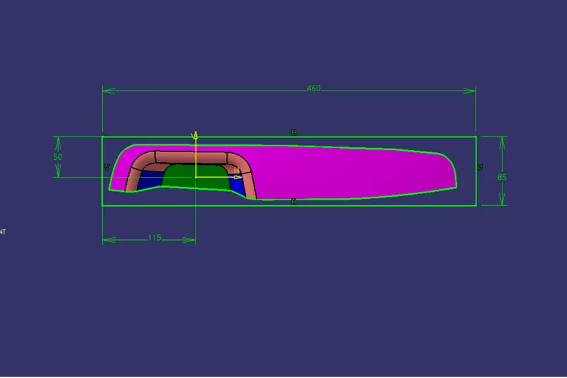
- Create a position sketch in which draw an rectangle enclosing the class A surface completly with sufficient margin.
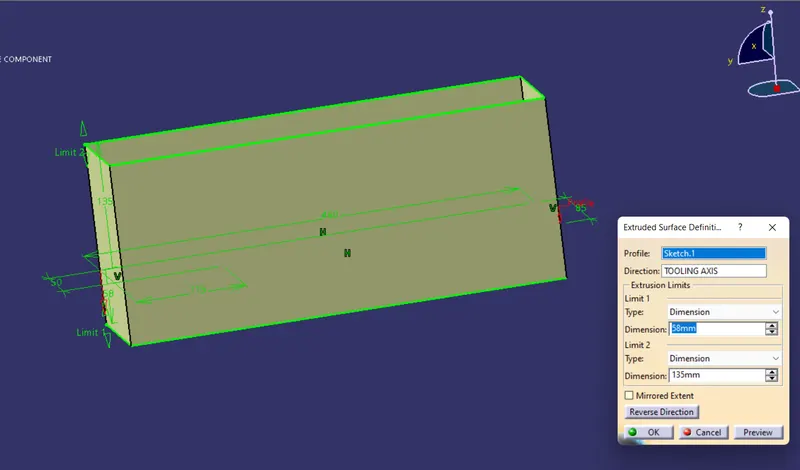
- Extrude the sketch along the direction of tooling axis.
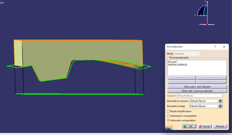
- Trim the resulting extrude with class B surface.
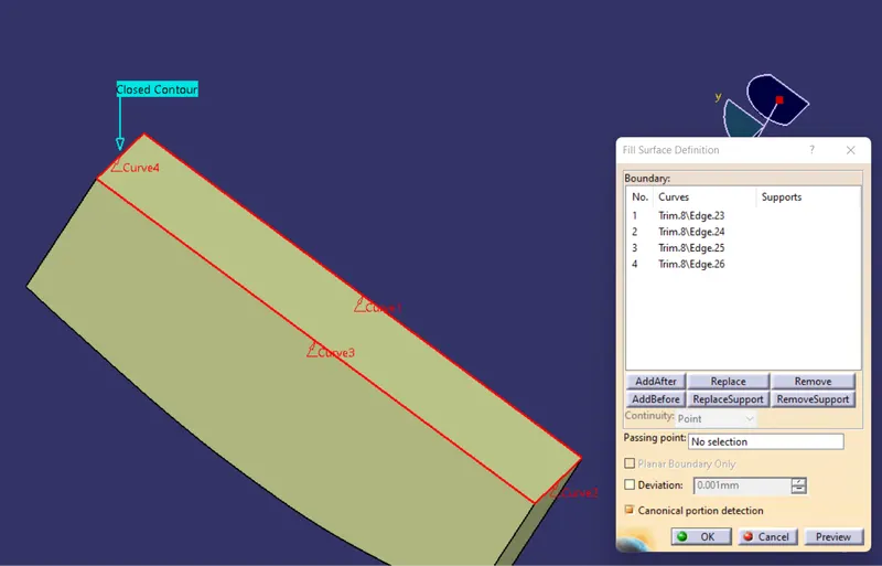
- fill the other end of the resulting trim using fill command.
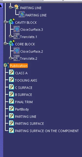
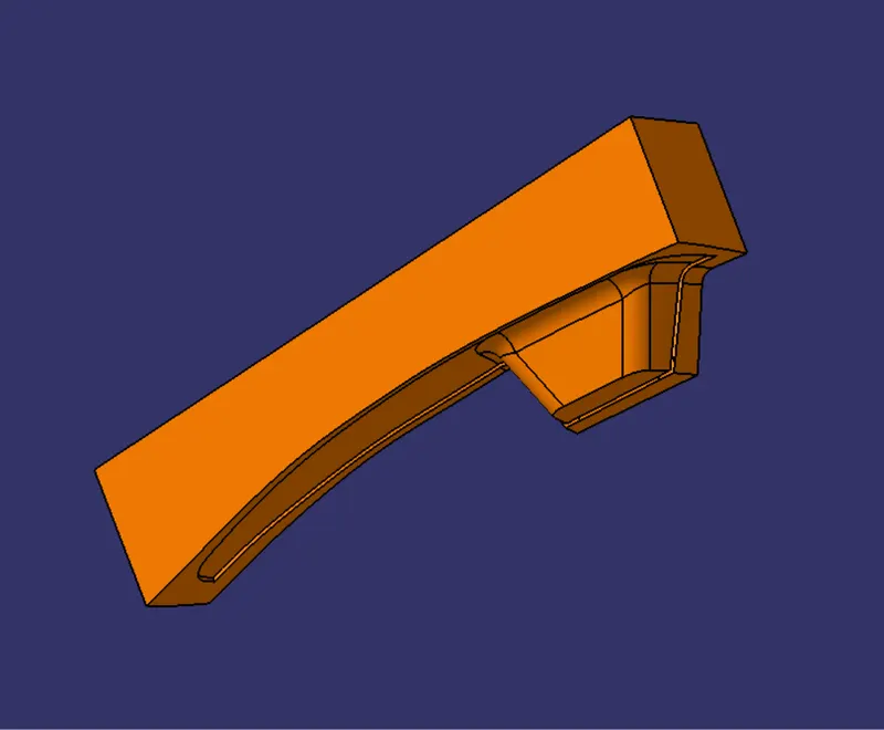
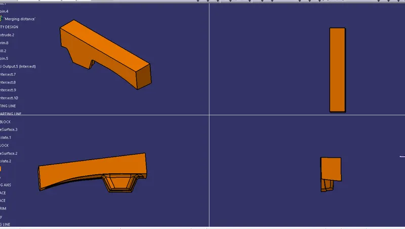
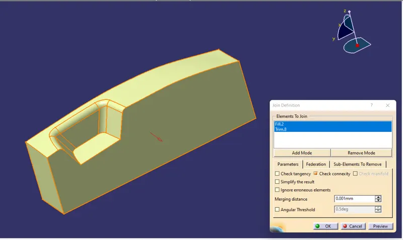
- Finally go to part workbench and use the closed surface command to convert the closed surface into solid body.
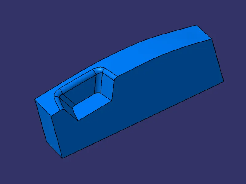
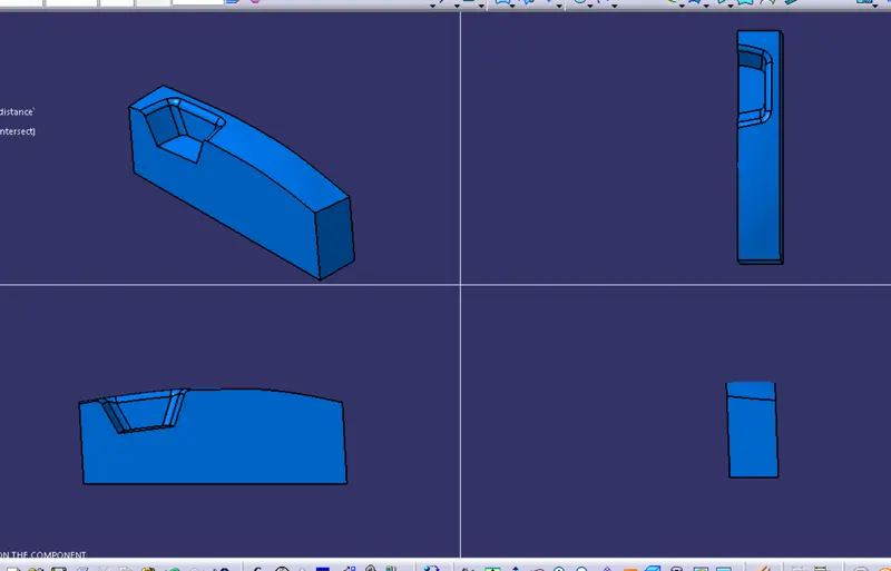
- The resulting solid part is the core for the switch bezel.
DESIGNING OF CAVITY
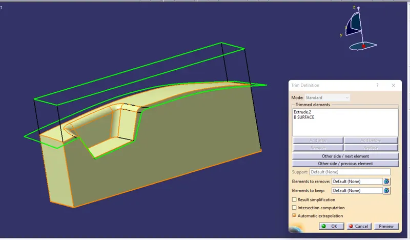
- Take the same sketch that was used in core design and apply extrude command and take the direction of tooling axis as the direction of extrude.
- Trim the class B surface with the resulting extrude.
- Cover the the opened end of the resulting trim using fill command, the resulting entity will be a closed shell of cavity.
- Convert the resulting shell into a solid body by using closed surface command in part workbench.
- The resulting solid body is the cavity for switch bezel.
CORE AND CAVITY DESIGN
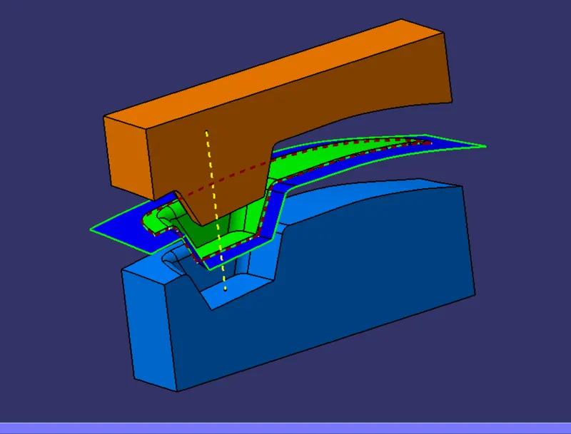
TREE STRUCTURE: