Door Arm Rest Week 8 Challenge
DOOR ARM REST DESIGN AND DRAFT ANALYSIS
OBJECTIVES:
- To create a tooling axis for class A surface of a door arm rest.
- To design class B and Class C surfaces for the door arm rest model by taking a class A surface as an input.
- To create a solid part model of the door arm rest out of class A, class B and class C surfaces.
- To do draft analysis of the door arm rest model using feature draft analysis tool.
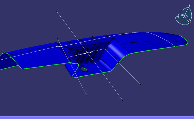
- To check for side core requirement if any and work on side tooling axis.
DESIGNING METHODOLOGY:
CREATION OF TOOLING AXIS
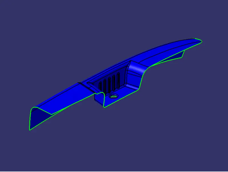
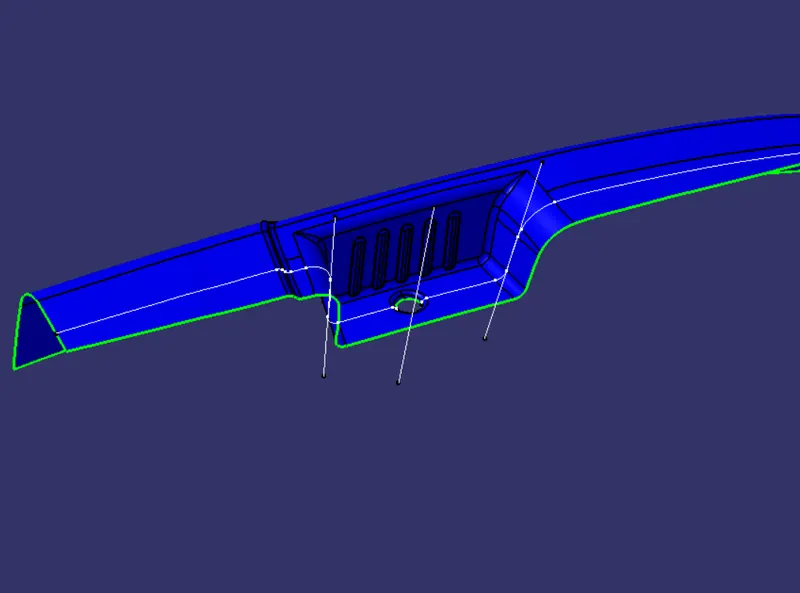
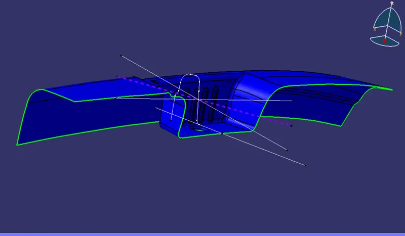
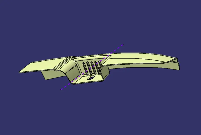
- On inspecting the class A surface in isometric view we can clearly see a pocket in the middle part of the surface and there is a hole in the middle of that pocket.
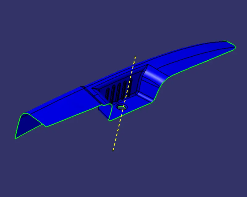
- According to the above analysis we can keep the tooling axis along the z direction because the hole can only be cleared through a tooling axis directed along z direction.
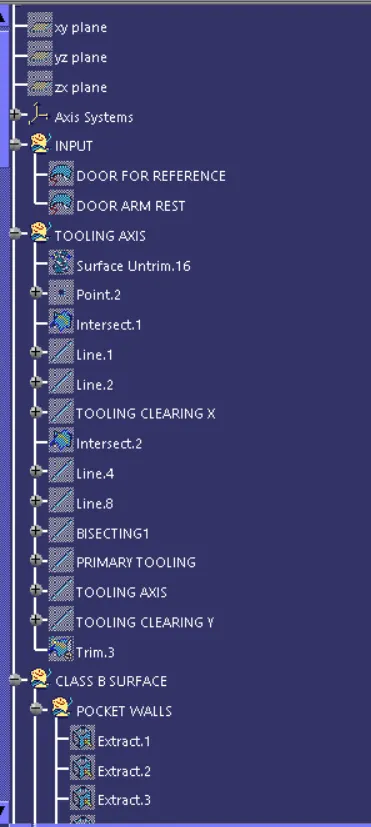
- To start with tooling axis creation first extract the base wall of the pocket and untrim it, then create a point on the middle of that untrimmed surface using "on the surface" option and keep the distance zero.
- since we have decided the tooling axis direction as z axis but in addition to that we also have to clear x and y directions.
- Insert an axis system on the point and then use the intersect command to intersect the zx plane of the axis system with the class A surface.
- Now draw two lines along the side wall of the pocket using the intersection profile created in the previous step.
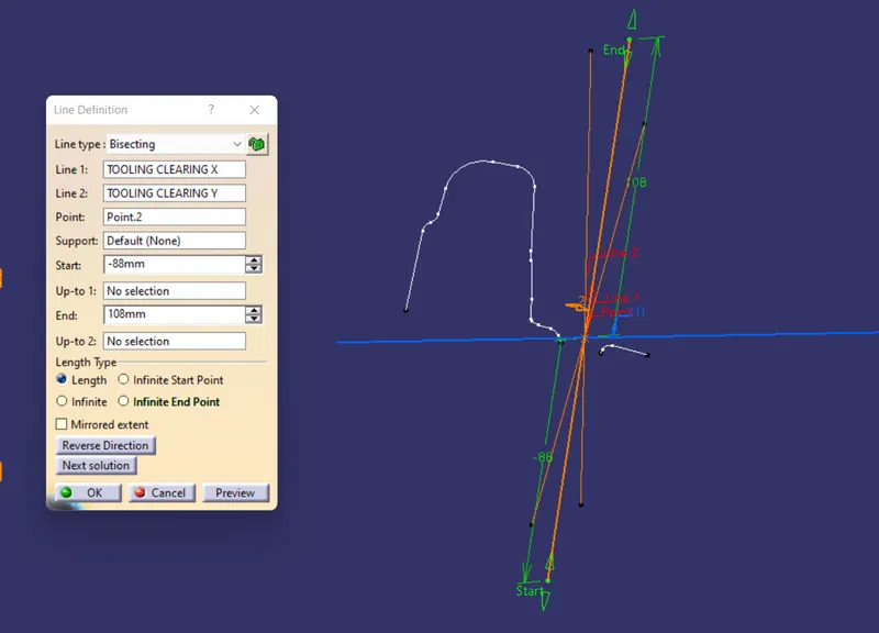
- Create a bisecting line using these two lines and make the support of that line at the point created initially. This line basically clears the tooling along x direction so we can name it as "line clearing x axis".
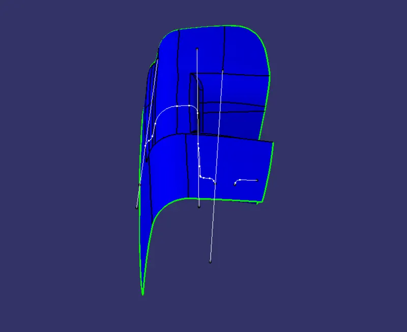
- Now again use the intersect command and intersect the class A surface with zy plane of the axis system.
- Create lines along the walls in a similar manner as we did for clearing x direction and create a bisecting line using these lines. The additional work we have to do in this case is that create one another line with an angle of 5 deg to the bisecting line and make the support of this line as the point we made initially. This line is the axis clearing Y direction.
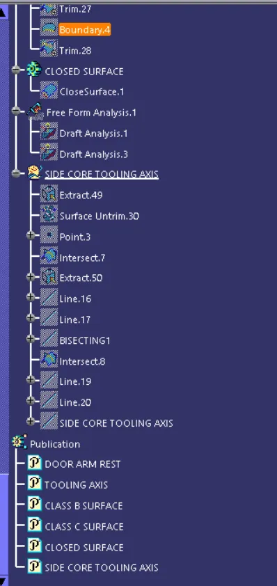
- Create a bisecting line using the lines clearing x and y direction. The resulting line is said to the main tooling axis.
FORMATION OF CLASS B SURFACE
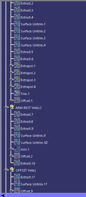
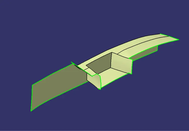
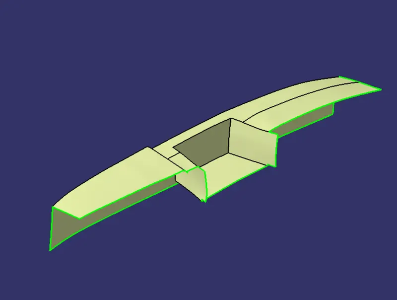
- To create the class B surface first we'll extract all the constituent surfaces of the class A surface except the filleted ones.
- After extracting them individually we will untrim them to bring them back into their respective primary shapes.
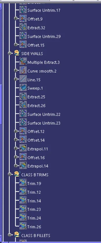
- Divide all the surfaces into different sets according to their functionality i.e pocket walls, arm rest wall, side wall and front offset wall.
- The untrimmed surfaces still don't intersect to each other completly, in order to make them intersect each other we will extrapolate them with point continuity option.
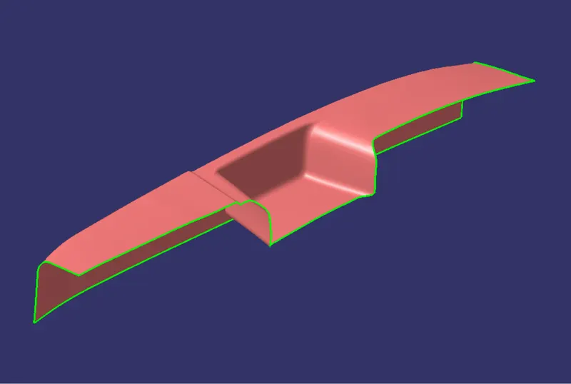
- Then we'll provide an offset value of 2.5mm (thickness of the model) to all the extrapolated surfaces using the offset surface command, make sure that all the surfaces are offseted to the inner side of the class A surface.
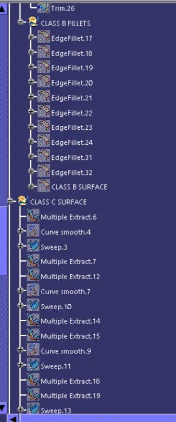
- Finally we'll trim all the surfaces one by one untill we join all the surfaces into a single entity. After applying fillets(class A fillet radius - wall thickness) to the final trim, the resulting surface that we'll get will be called as the class B surface.
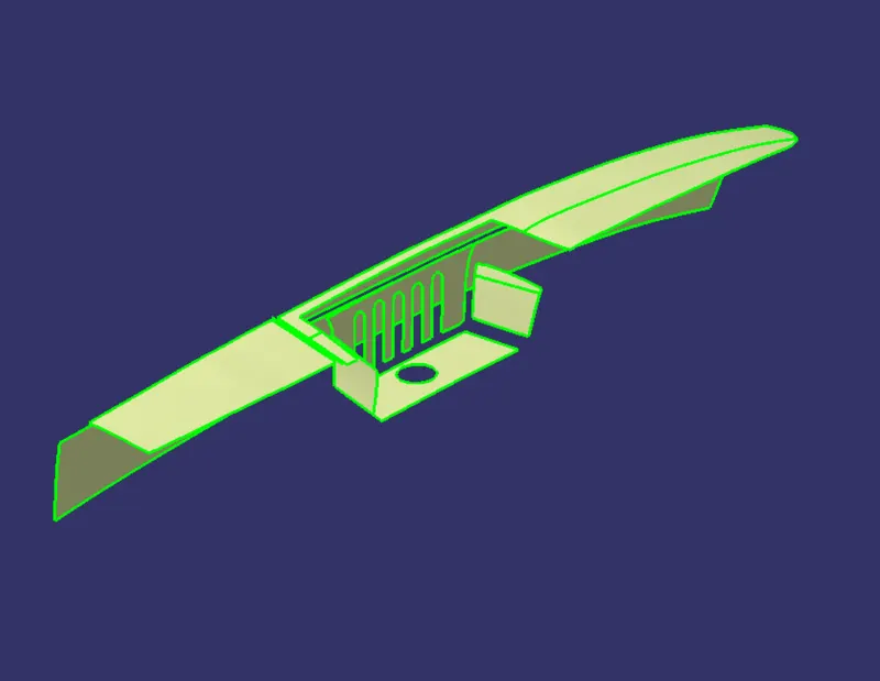
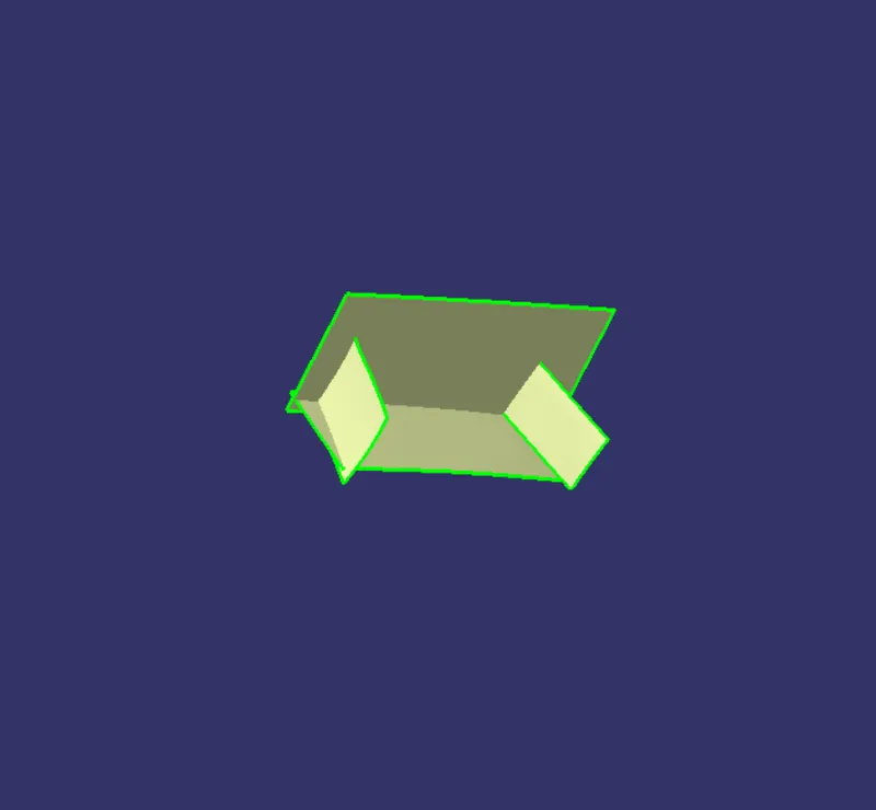
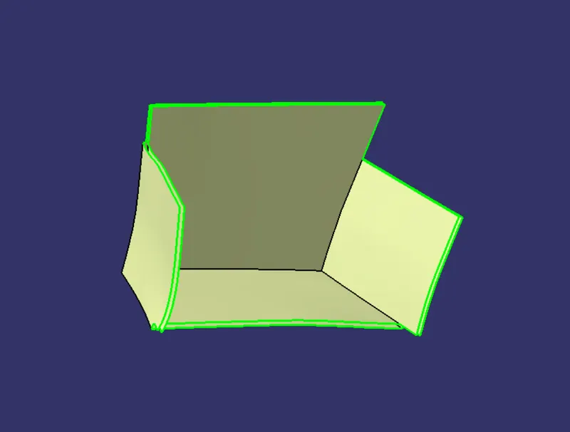
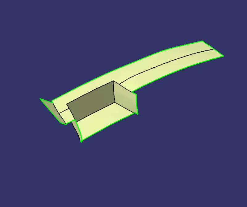
FORMATION OF CLASS C SURFACE
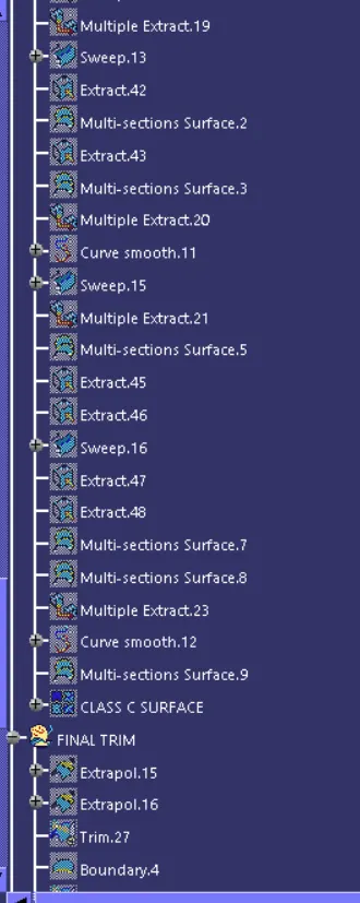
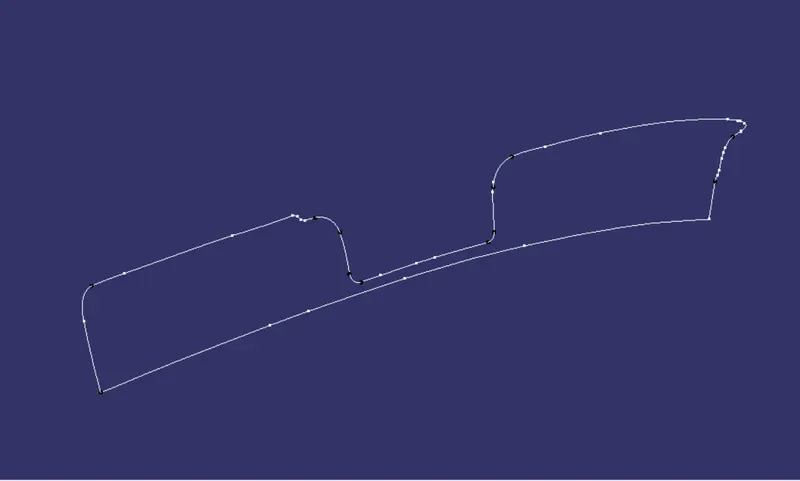
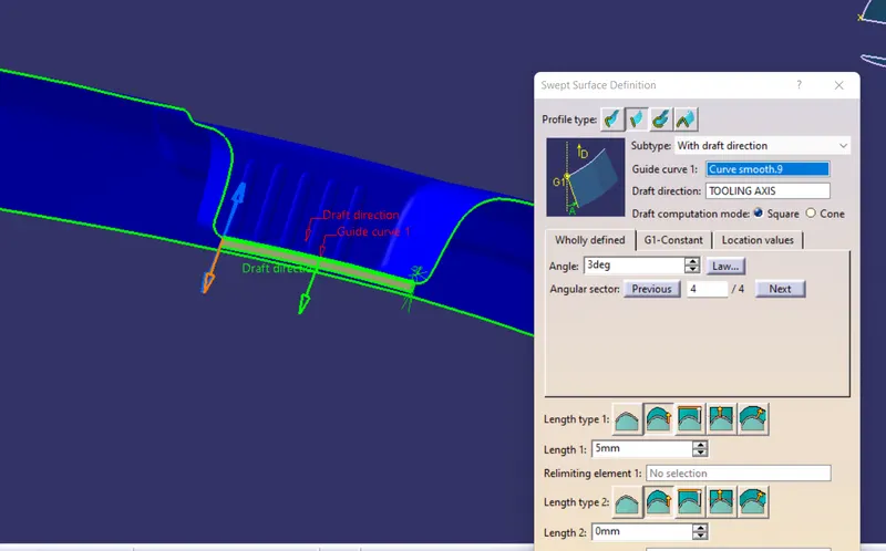
- Since the shape of class A surface is such that the class c surface can't be created completly by "with refrence to draft axis" option of sweep.
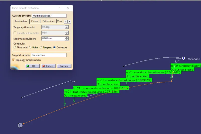
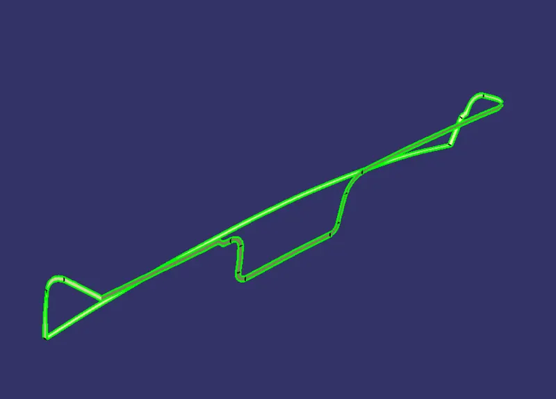
- Here we won't extract the complete outer boundary in once but we'll extract the boundary into different pieces of curves and then work on them to construct class c surface.
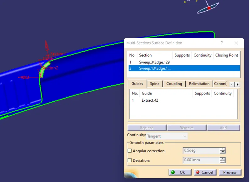
- For the boundary sections which are perpendicular to the tooling axis we'll use sweep command and for the remaining boundary sections we'll use multisection command, and finally we'll join them altogether. The resulting surface will be our class C surface.
FORMATION OF CLOSED SURFACE
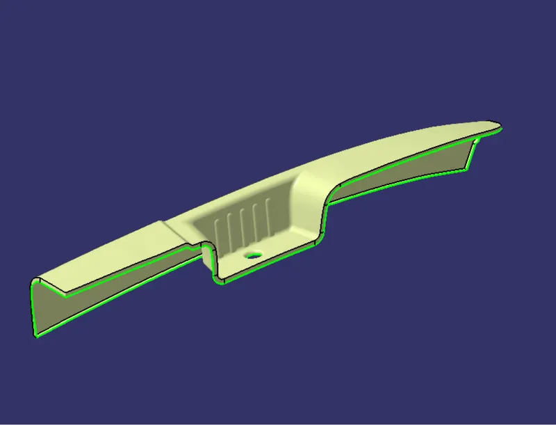
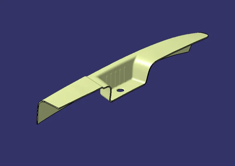
- The first thing that we need to do is to join class A surface with class C surface, while joining them we can face problems because of the gaps between the adjoining edges of the class A and class C surfaces. To solve this problem we can extrapolate any one or both the given surfaces according to requirement.
- The second task would be to split the resulting join that we created in the first step with class B surface. The resulting entity that we'll get will be the closed surface model of the door arm rest.
FORMATION OF THE SOLID PART
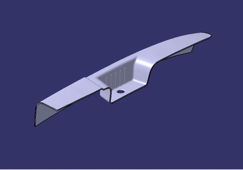
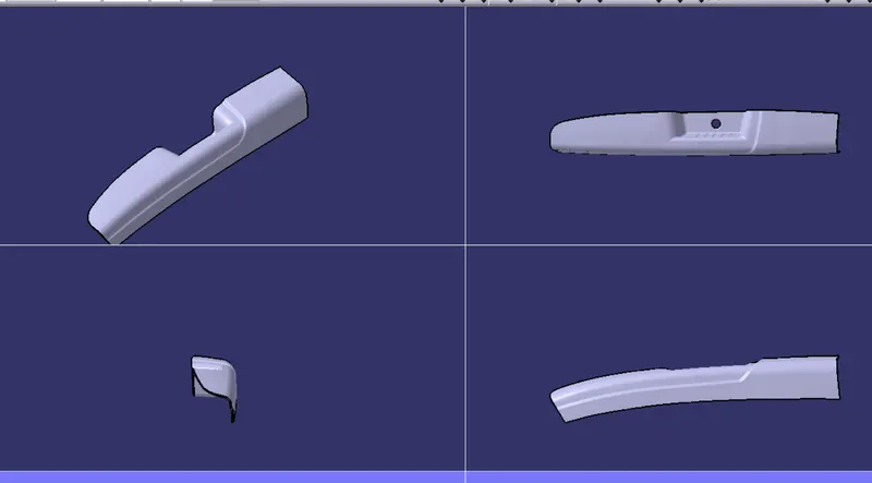
- Go to part workbech and use the closed surface command and the resulting body we'll get is the solid part model of the door arm rest.
DRAFT ANALYSIS
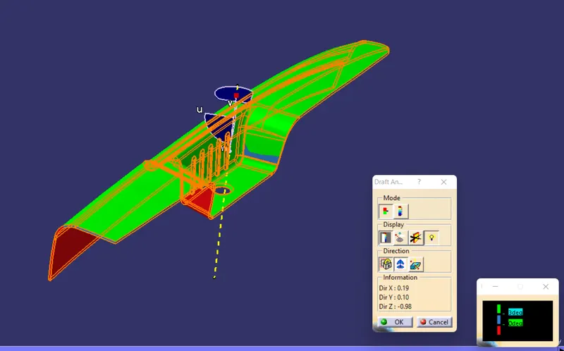
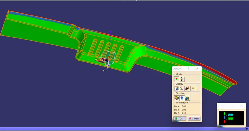
- Go to insert>analysis> feature draft analysis.
- Click on the compass icon and align the compass axis with the tooling axis of the part model.
- Click on the lock icon and then cilck on the part model.
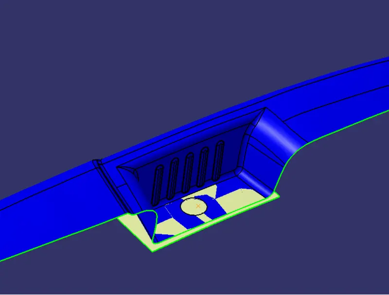
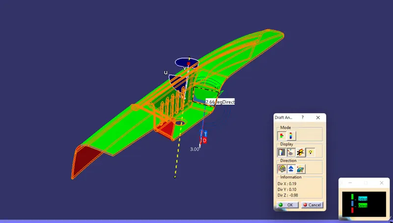
- In case the top surface or class A surface shows red colour then click on the reverse draft direction icon.
CONCLUSION OF DRAFT ANALYSIS:
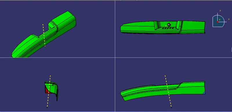
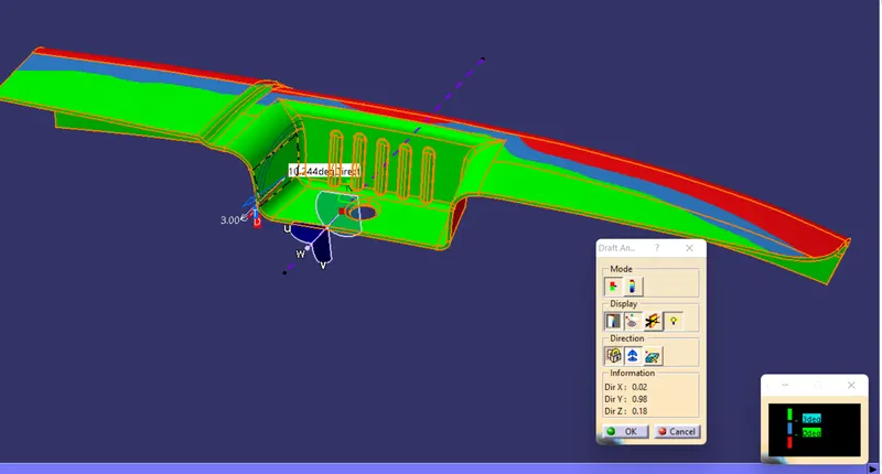
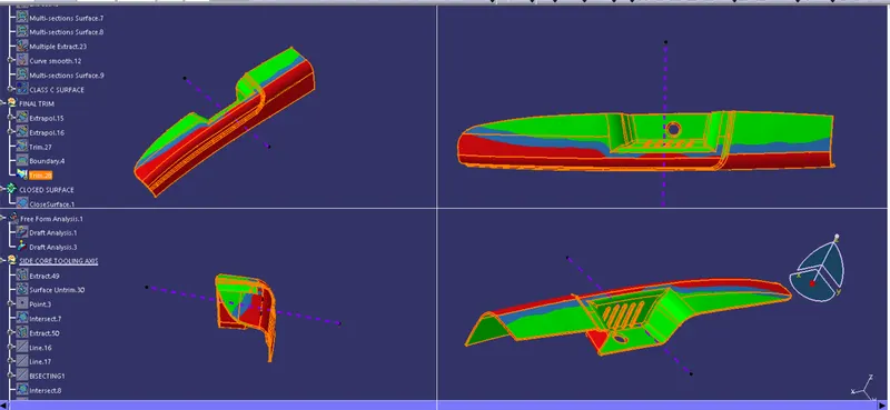
From the above shown draft analysis we can clearly see some blue patches on the side walls of the pocket, which clearly shows that the draft value at such regions is below the permissible draft value of 3 degrees, which means our tooling axis is not sufficient to clear all the regions of door arm rest model.In order to deal with this problem we need to go with a side core consideration.
SIDE CORE TOOLING AXIS AND DRAFT ANALYSIS
POINTS TO REMEMBER
- Fillet radius for class B surface = fillet radius of class A surface ± wall thickness.
- Always give draft to the outward direction(away from the tooling axis ), doing this would lead the intersection of parting line with class B surface boundary and hence the class A surface will come out to be a smooth surface without any extra material around it.
- second benefit to giving draft in outward direction away from the tooling axis is that it would not allow the moulding defects like flow lines to happen.
- After doing the final trim always make sure that there is no gap formation between any adjacent surface because that would lead to create problems in solid part formation, we can check it by two methods.
- First one is to apply boundary to the final trim, if the boundary command pops up an error showing no boundary can be formed it means the surface is completly closed.
- Second one is to apply join comand, if any green line appears to the edges of the final trim it means there is gap in between the surfaces but if no green line is hilighted then the surface is completly closed and have no gaps.
FEATURE TREE: