WIRING HARNESS FOR BACKDOOR
REPORT ON WIRING HARNESS FOR BACKDOOR
Statement of assignment:
Route the Wiring harness on Given car body and Prepare flatten view drawing in CATIA V5. Application of all Packaging rules, Industry best practices studied in this course shall be demonstrated in design. Apply Protection coverings as required.
Available connector 3D data can be used, or you can download the connectors from www.te.com
Prepare & Submit all necessary reports like clearance, Clipping/Clamping selection, Harness fixing requirements, Harness continuity, Assumptions if any along with CATIA 3D data.
Introduction
Defining the Mechanical connectors & supports into electrically defined parts and storing them in a Catalogue.
Steps that are to follow to define the following connectors as Electrical Connectors using Electrical Part Design Workbench in CATIA V5.
- Initially open the "Backdoor.igs" file in CATIA V5 which can be downloaded form the above link.
- Now, for connecters open part design workbench specify the Bundle Connection Point and Connector Connection Point. Adding Axis System would be a added benfite at this point of time. A flowchart is also provided below for better understanding.
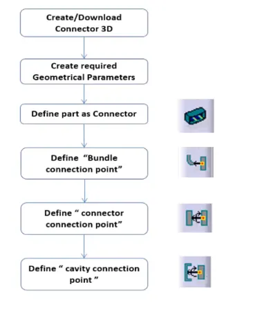
- Then switch to Electrical Part Workbench in CATIA V5 and define the connecter first with no.of terminals.
- Now define the Bundle Conncetion Point and Connector Connection Point.
- Make sure to save the file in a requried folder. Do the same for all connectors.
- For supports, define the parameters as required for enterance and exit points for the bundle route.
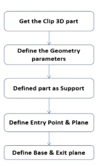
- Define support icon.

- For an example, a screeshot is also provided below.
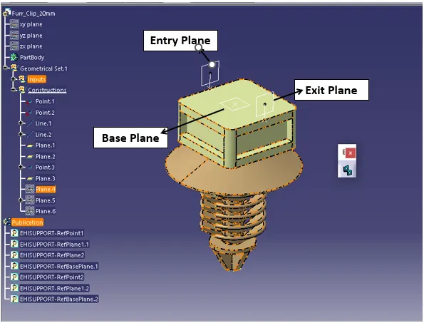
- Now create a new catalog file and add family as Connectors and supports, Then save them in apporpriate folder.
- Just for Channel protection covering define the part as an equipment and define the bundle connection point on entry and exit points of the channel as needed.
- Store the CATpart files in catalog by clicking on store device option and storing them in connectors catalog.
- Check the CATpart files are stored in catalog file.
Image of the Catalog
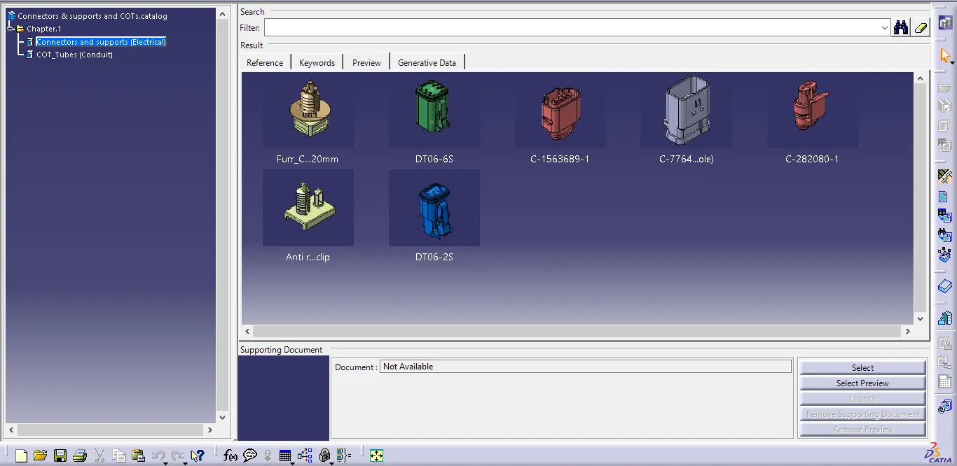
Image of the Connectors Catalog
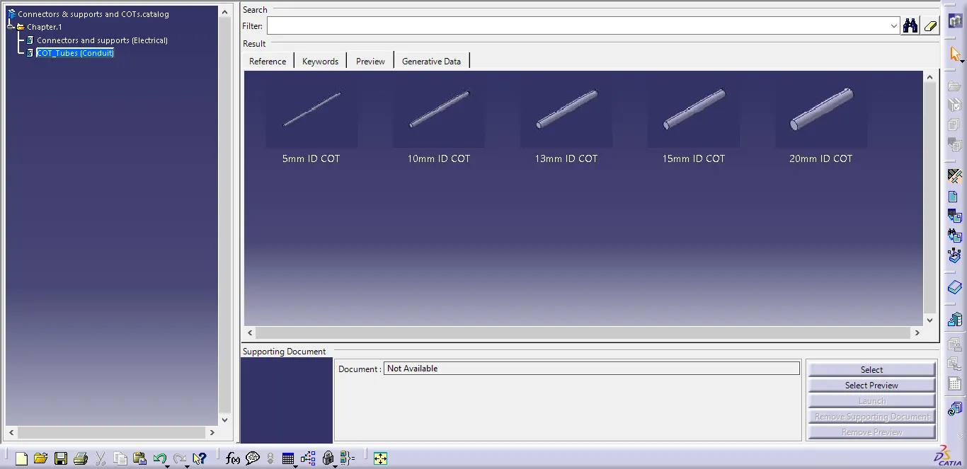
Image of the COT_Tube Catalog
- Every part for the Context Assembly was imported from here, and multiplied by copy and paste option.
- To break the link between the parts, use Paste Special Option and Break link.
Preparing the Assembly file and Geometrical bundle file for routing Wiring Harness
Steps to create the Assembly Product file and Geometrical Bundle for Routing Wiring Harness.
- Create a new product file and rename it as "Context Assembly of Backdoor Wiring Harness"
- Now import the Backdoor file first and arrange the appearances as wished.
- Place the interconnector onto the Sealing flange using Anti-Rotational fir tree clip.
- Now create a new file for the wiring harness geometrical bundle and before converting the file into Geometrical bundle import all the required files into it and arrange the positions mannually.
- Generally 4 pole connectors are used for Rear Lights and Camera. For Number plate lights and Rear Middle brake light we use 2 pole connectors. For Wiper Motor we use 6 pole connectors.
- Import the furr tree clips to arrange the wiring harness to avoid unnesessary space consumption & to route as per industry standards.
- By using the "Catalog Browser" option import required connectors and supports from "Connectors & supports Catalog" which we have created earlier.
- Position them as shown in them as required by using Smart Move/ Snap/ Compass or Translation and Rotation Option. This option can be found in "Assembly Design" Workbench only under Move Toolbar.
- Now convert the document into geometrical bundle document by using
 this icon in "Electrical Harness Assembly" workbench.
 - Now add a Multi-Branchable file in Geometrical Bundle Product File by using "Multi-Branchable Document" option under Creation Toolbar in Electrical Harness Assembly Workbench.
- Now switch to Electrical Harness Installation Workbench and Click on "Branch definition" and create bundles. If at any point we need a sub-branch in routing from the main branch, we need to use "Add branch point" option so that there will be a break on main bundle.
- While creating the routing we also need to define the route definition by providing nessesary details like length/slack and perfect tangents as we required.
- And also use the clips and clamps to route the wiring in perfect manner.
- Now add the Protection Coverings using this
 icon from ceartion toolbar from "Electrical Harness Assembly" workbech. and aslo ensure the start & end extremities.
 - After Completion of the Routing, check all the coverings and clamps that are arranged during routing and check the clearance maintained or not.
- Now save all the file using Save management option, to save all the files in the same folder use propagate directory option. Then click OK.
- For Flattening of the file we need to create new file and set the Flattenning Parameters, import the geometrical file into it and flatten the file.
Harness Fixing
When assembling electrical harnesses, harness fitting is essential to assuring wire order, safety, and system functionality. The requirements, methods, and factors for fundamental harness mending are described in this study.
Importance of Harness Fixing:
Harness fixing:
- Ensures reliable connections.
- Prevents wire damage.
- Facilitates maintenance.
- Meets safety standards.
Fixing Techniques:
- Clipping: Secure wires using clips along the harness.
- Clamping: Fasten harness with clamps to prevent movement.
Key Requirements:
- Positioning and Alignment: Neat arrangement, no overlaps.
- Load Distribution: Even weight distribution, appropriate load capacity.
- Vibration and Shock Resistance: Dampen vibrations, withstand shocks.
- Temperature and Environment: Handle temperature, moisture, chemicals.
- Accessibility: Easy access for maintenance.
Selection Considerations:
- Component Specs: Manufacturer specifications, compatibility.
- Installation: Proper methods, torque, adherence to standards.
- Standards: Follow industry regulations (ASME, ISO).
Clipping and clamping selection data
Clipping and clamping in wiring harness assembly involve securing and organizing wires to prevent damage. Clipping uses clips to hold wires along the harness, while clamping uses clamps to secure the harness in place. Selection factors for both include wire size, routing, vibration, temperature, and material compatibility. Engineers consider manufacturer specs, load capacity, installation methods, and industry standards when choosing clips and clamps.
Clipping: Clipping is the process of attaching wires and cables throughout the length of the wiring harness using a variety of clips, clamps, or fasteners. These clips, which are frequently made of plastic, metal, or composites, are designed to hold wires securely without causing damage. The choice depends on elements including wire diameter, harness design, weather, and mechanical requirements. Clips can be fastened to brackets, parts of the vehicle's body, or other useful anchoring points.
Clipping Selection Considerations:
- Wire diameter and bundle size.
- Harness routing and geometry.
- Vibration and mechanical stress.
- Temperature and environmental conditions.
- Electrical isolation and grounding needs.
- Material compatibility and durability.
Clamping: A wiring harness is clamped when it is fastened to fixed locations or structures using clamps, ties, or straps. These parts prevent the harness from moving too much or sagging or oscillating, especially in areas where chafing or mechanical stresses are more likely to occur. There are numerous clamp designs available, including versions with adhesive backing, screws, or rivets.
Clamping Selection Considerations:
- Harness weight and tension.
- Positioning and alignment of wires.
- Clearance requirements.
- Resilience against vibration and impact.
- Compatibility with harness materials.
- Installation and maintenance ease.
Selection Data: Engineers and designers take into account a variety of technical requirements and recommendations when selecting clips and clamps for wiring harness installation. Relevant facts include:
- Manufacturer specifications for clips and clamps.
- Material composition and properties. (e.g., temperature resistance, chemical compatibility)
- Load-bearing capacity and stress limits.
- Installation methods. (e.g., adhesive, fasteners)
- Compliance with industry standards. (e.g., ASME, ISO)
- Testing and validation data for chosen components.
Images of the Wiring Harness Context Assembly file with Feature tree.
Isometric view of the V16 Engine Wiring Harness Context Assembly
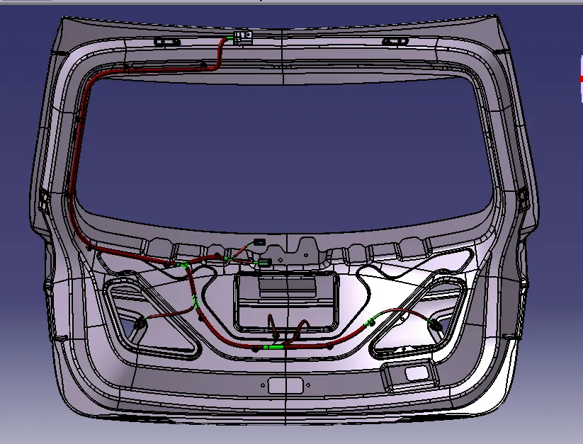
Image of Wiring Harness Geometrical Bundle
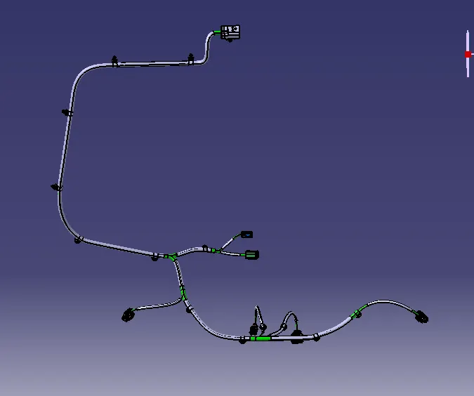
Image of Wiring Harness of the backdoor in details
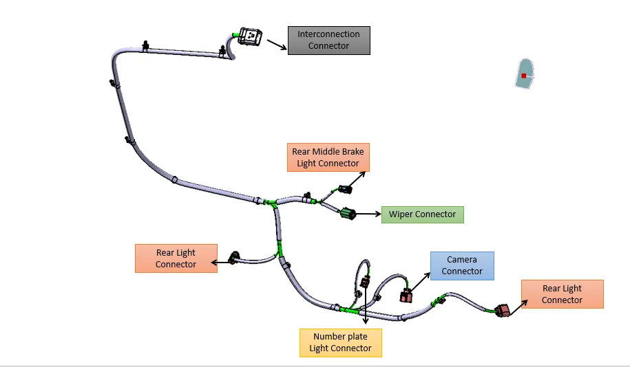
Image of wiring harness bundle continuity checking
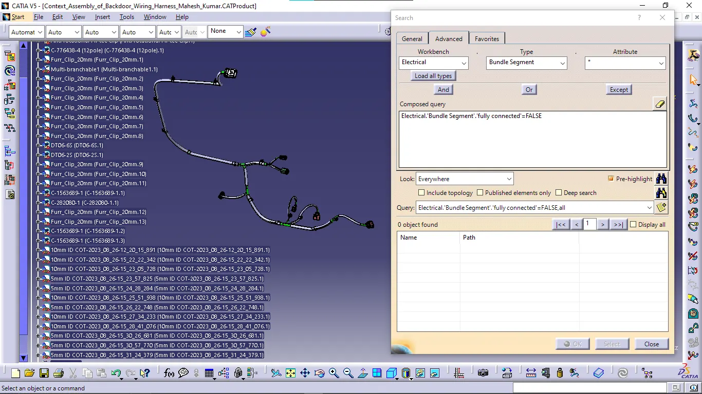
In false area no objects are found that means every bundle is connected fully.
Image of Wiring Harness Flattening file
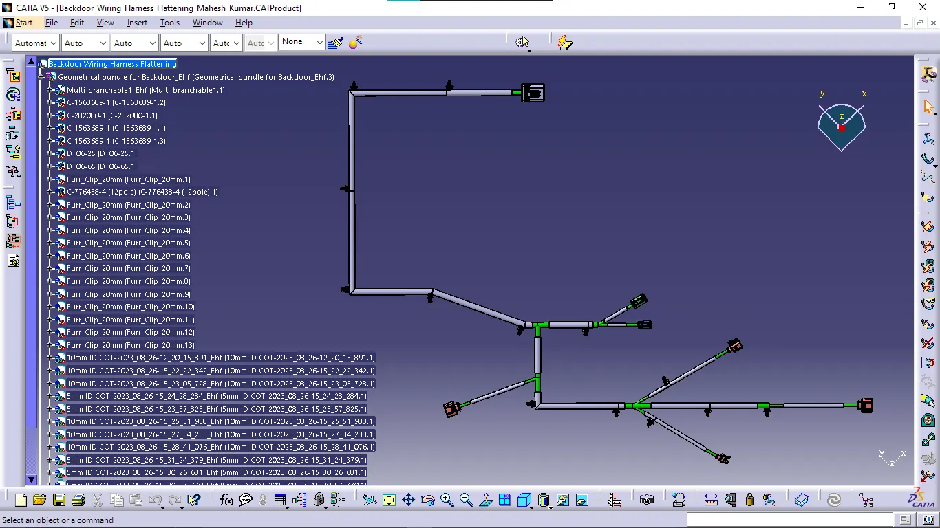
Image of Wiring Harness Flattening Drawing
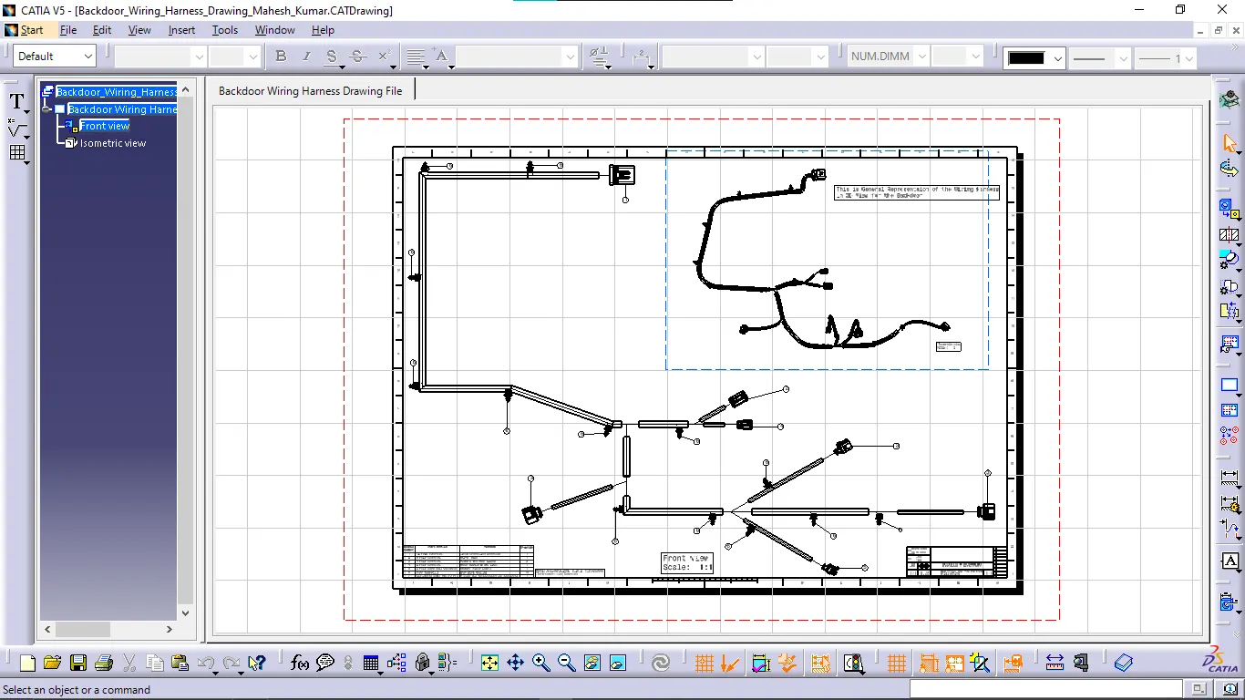
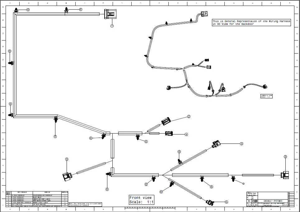
Image of Wiring Harness Flattening Drawing PDF file
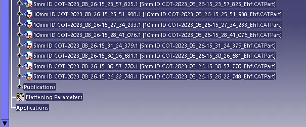
Feature tree Images of Wiring Harness Product file
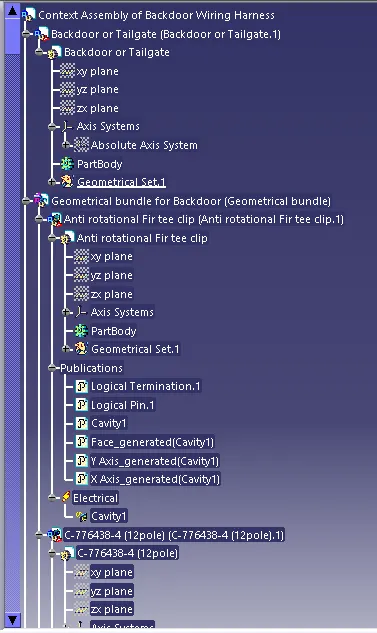
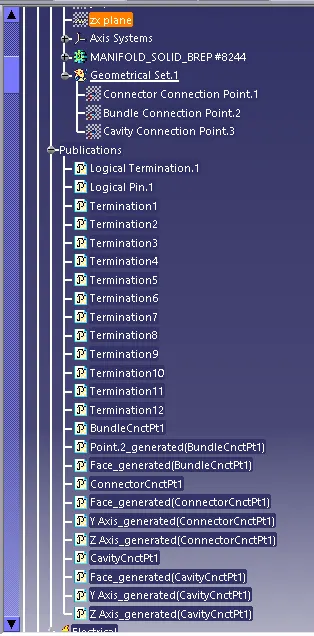
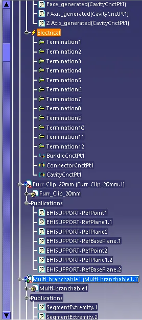
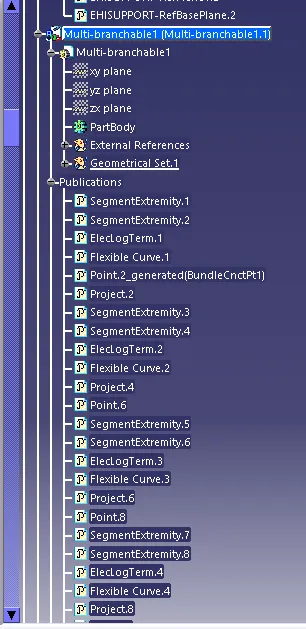
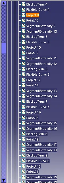
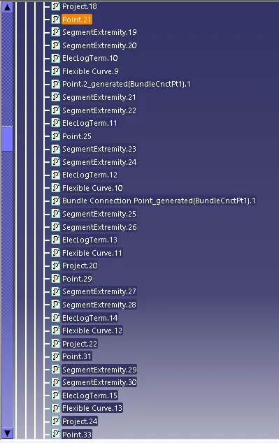
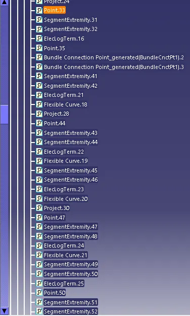
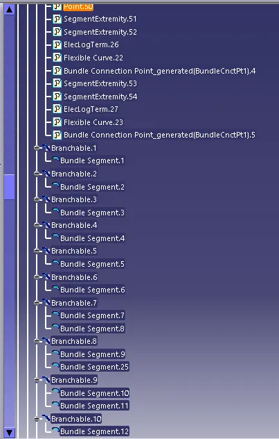
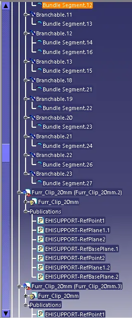
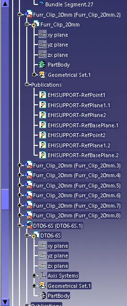
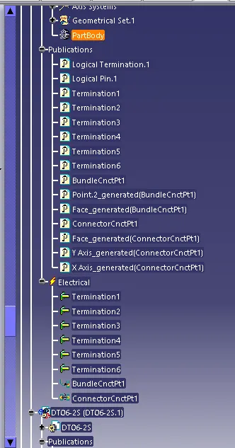
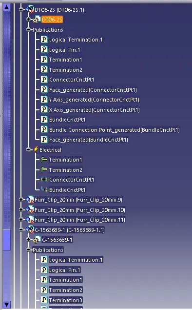
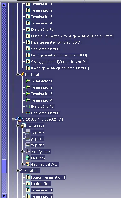
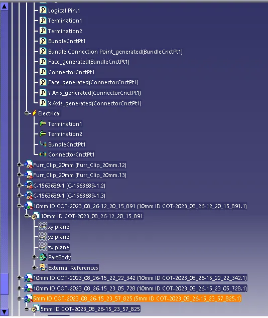
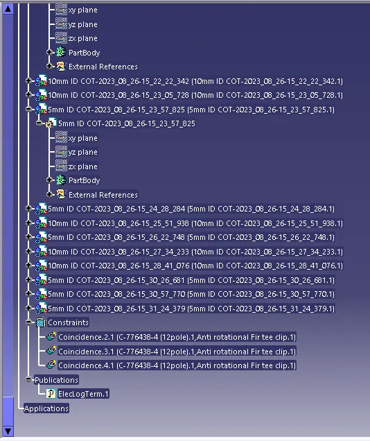
Note: Some of the product files are not expanded in feature tree as those files are repeated.
Images of Wiring Harness Flattening Product file with Feature tree
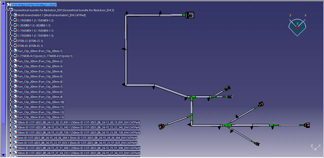
................................
NOTE: All the files have been uploaded as a Single ZIP file and attached.