Week 14 challenge
REPORT ON ASSEMBLING & APPLYING GD&T TO THE BUTTERFLY VALVE ASSEMBLY DRAWING
The steps to build the butterfly valve assembly are as follows:
- Open the NX program first, then make an assembly file in the necessary directory. Verify that the same folder contains all of the component files.
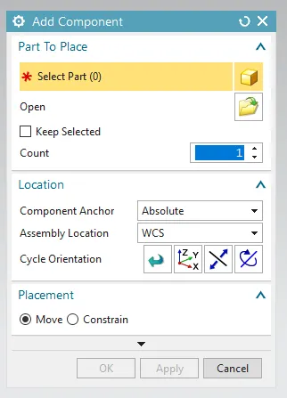
- We use the Add Component command from the assemblies ribbon to import the part files because we are employing the Bottom-up technique in the assembly. [which is displayed below]
- To import the files, click the Open icon and choose the necessary ones.
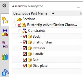
- Once they are imported, make sure all of the parts are imported by checking the assembly navigator box.
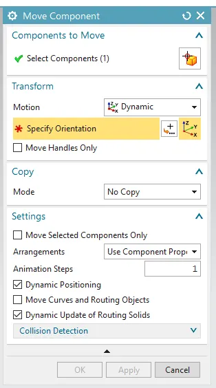
- Now use the Move Component icon from the assembly ribbon to arrange the parts in the desired orientation.
- By choosing the component that has to be attached, specify its orientation in relation to the other component.
- Using Assembly Constraints fix the body of the butterfly valve.
- In below, Fix Constrain is the selected icon.
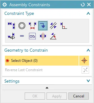
- By choosing the component that has to be attached, specify its orientation in relation to the other component.
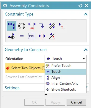
To attach, align, or deduce the component's center or axis, select one of the available options.
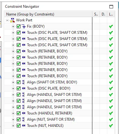
- Use the Constrain Navigator to confirm whether or not all constraints are implemented.
- To improve Assembly visibility, click Show and Hide (Ctrl+W) to hide the constraints, then save the file.
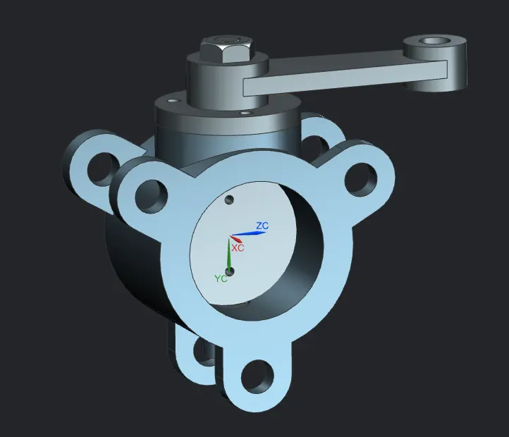
- This is how the 3D Assembly will look at the end.

The steps to draft the butterfly valve's GD&T drawing sheet are as follows:
- Select the drafting application mode and provide all required information, such as sheet size, drawn by, checked by, etc.
- Import the model's Base view in the necessary scale so that it will fit on the drawing sheet. [My favored scale was 1:2]
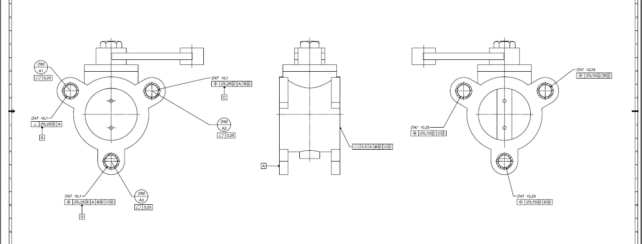
- To achieve three views in total, add a projection view from it and project a view from the first projected view once more.
- By modifying the font size, allocation, etc., you can provide the basic dimensions with tolerances.
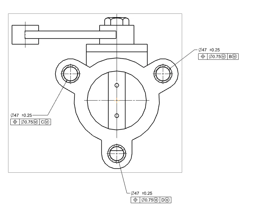
- Now, give the required GD&T data using the Feature Control Frame icon from the annotation window. This will help to ensure error-free manufacturing of the part.
- Additionally, include datums. These are needed to set the part and verify its dimensions, as well as to aid locate the point at which the part will come into contact during assembly.
- Constrict the body's other side ears using datums.
- Examine every surface and feature of every size to see whether GD&T is required and give it.
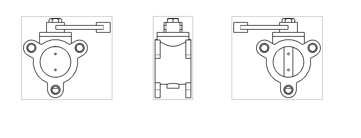
- To utilize the file for features, save it and export it as a PDF. The completed drawing would look like this:
............................................................................................................................................................
NOTE: A ZIP file containing all part and assembly files has been uploaded and attached.