Roof Design
ROOF DESIGN
OBJECTIVE:
- By using NX cad designing a Roof for a car by following the given parameters.
- Designing a car roof with necessary flanges and reinforcements, such as ditch areas, front roof rails, bow roofs, centre roof rails, and rear roof rails for the specified style surface, is the goal of this project.
- To ascertain whether the bow roofs are in the proper positions, undertake a curvature analysis on the roof and compute the heat distortion and snow load criterion.
- Calculating the section modulus and moment of inertia for Bow roofs with a central roof rail. both the front and back roof rails.
- Analyze each reinforcement using the draft analysis method.
Introduction:
Any product's design begins with a requirement. Based on the requirements, the design engineer creates a sketch of the product. Using cutting-edge CAD software, the 2D sketch with the correct dimensions is then turned into a 3D model. Every product that is designed should be able to be made; this is another crucial aspect of design. So, the design engineer's job is to create products that are simple to make and less expensive to produce. This is where design for manufacturing and design for assembly play a part in the development of any product. The design development process continues until the final product meets the needs of the client. In this project, a car roof is the final product that will be designed.
Car Roof and it's Reinforcements:
An automobile roof or car top is the portion of an automobile that sits above the passenger compartment, protecting the vehicle occupants from sun, wind, rain, and other external elements. Because the earliest automobiles were designed in an era of horse-drawn carriages , early automobile roofs used similar materials and designs.
If the roof is flat, it is particularly fragile and unable to withstand forces like snow, so reinforcements like bow roofs, front roof rails, central roof rails, and rear roof rails are introduced and linked to the flat surface of the roof using various joining techniques.
Different types of reinforcements:
- Front roof rail,
- Bow roofs,
- Central roof rail and
- Rear roof rail.
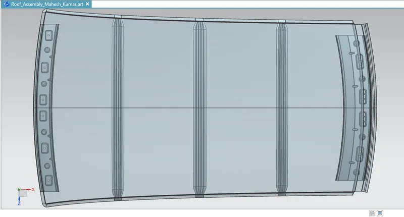
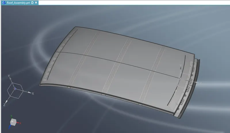
Image of Roof assembly
FRONT ROOF RAIL :
The front roof rail is what connects the body side outer and inner panels as well as the wind shield glass. Here, the front roof rail is created using the provided master section.
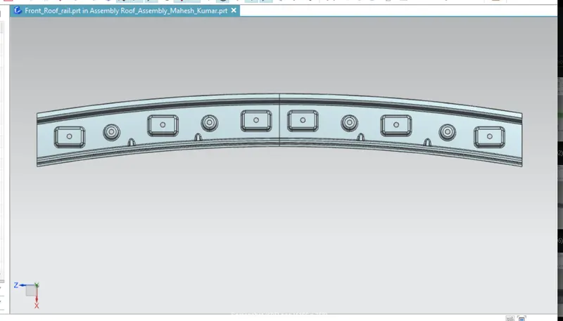
Image of Front Roof Rail
REAR ROOF RAIL :
Rear roof rail which joins the Back Door and the Outer Roof Panel.
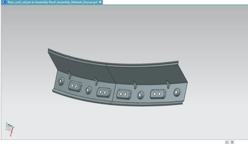
Image of Rear Roof Rail
CENTRAL ROOF RAIL :
The flat portion of the roof is more prone to failure due to the action of stress, hence a central roof rail aids in properly supporting it. The B-pillar support structure is connected to the central roof rail, which is typically located in the center of the roof. During the Tool-over test, the central roof rail contributes to the strength of the roof. The main roof rail is 1.25 mm thick.
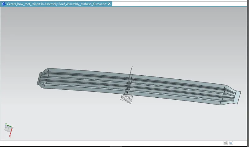
Image of Center Bow Roof Rail
BOW ROOFS :
The purpose of bow roofs is to increase the roof structure's torsional rigidity and load carrying capacity. The amount of bow roofs that are present depends on the size of the roof as a whole. At now, this project is adding two bow roofs.
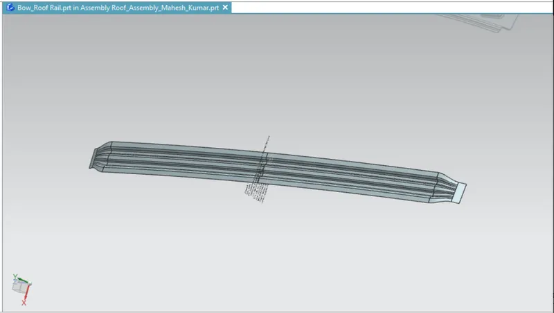
Image of Bow Roof Rail 1
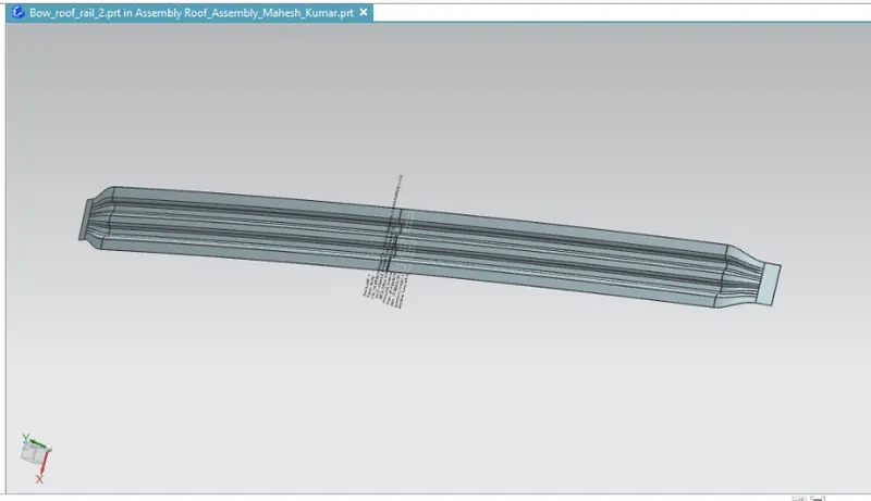
Image of Bow Roof Rail 2
JOINING PROCESS:
Mastics are inserted between the outer roof panel and reinforcements. Wherever the mastic is introduced, the strength is noticeably improved.
Furthermore, spot welding is used to attach the reinforcements to the exterior panel.
ROOF'S DESIGN CONSIDERATIONS:
- Visibility standards
- Draft angle for better tool angle
- Roof head space
- Curvature analysis
- Criteria for heat distortion and snow load
TEST FOR ROOF CRUSH:
The roof crush test was developed by the Insurance Institute for Highway Safety (IIHS). After reviewing the numerous accidents, IIHS subsequently established some rules regarding how to carry out the crush test. With the help of the test findings, IIHS rates a product. They consider two factors when rating something.
How fast a rollover can be avoided and how much protrusion is left after the rollover?
ROOF CRUSH TEST PURPOSE:
To reduce protrusion into the passenger compartment as much as possible so that the air bags and seat belts can properly secure the occupant.
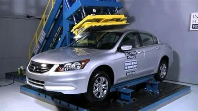
THESE ARE THE REQUIREMENTS FOR A ROOF CRASH TEST:
For the ceiling crush test, there are two requirements that must be met:
- ORIGINAL SITUATION:
Lock each and every entrance and Shut all of the openings.
- SECOND CIRCUMSTANCE:
Fix the body sill or chassis frame horizontally on a firm lever surface.
APPLICATION TECHNIQUE FOR THE FORCE:
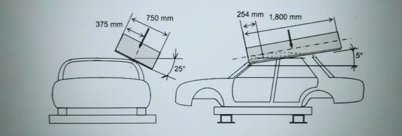
The load is given so that it is tilted 50 degrees from the front to the back, and it will be 1800 mm long and 750 mm wide. The load is given at a distance of 250 from the roof's flatness. The weight is applied to the roof for almost 120 seconds, and it crushes at a speed of 13 mm per second or less.
RESULTS:
If the displacements goes above the requirements level then we have to increase the bow roof thickness or add more mastics points to increase the strength . the stronger the roof the better it can protect the occupants in the roll over crashes.
HEAT DISTORTION STUDY FOR ROOF :
The heat distortion study plays a major role in sheet metal usage . Heat distortion temperature is a temperature limit above which the material cannot be used for the structural applications . This study is used to predict the heat distortion temperature at where the material starts to soften when exposed to a fixed load at elevated temperature . In order to avoid bending or damages on the roof, based on the heat distortion temperature , this study will predict the bow roof position which helps to strengthen the roof .
Bow–Roof Prediction Formula
W = [1.73 x 10^(-3) x L] + [1.85 x 10^(-8) x (R^2)/t] + [ 1.10x10^(-3) x l] - 2.68
Where,
L = Roof Length in X-Direction[mm](Roof dimension in 0-Y)
R = Roof curvature
R = 2(Rx*Ry)/(Rx+Ry)
Rx = X curvature
Ry = Y curvature
t = Roof plate thickness [mm]
l = Bow Roof Span [mm]
Judgment Condition
OK< 2.7
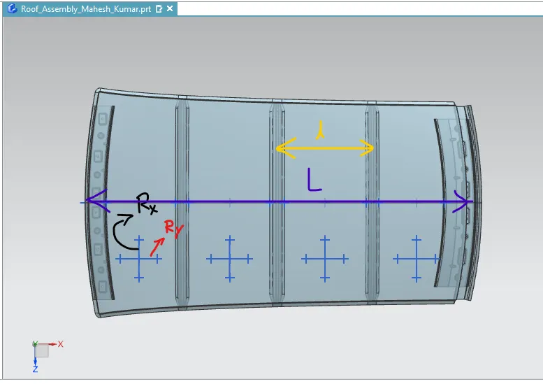
After Appling Calculations:
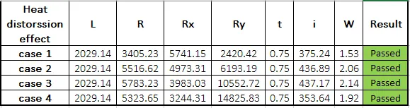
Image of Heat distorssion Calculation part
The above chart shows that all values of w are below 2.7 and do not exceed 3.1, indicating that the bow row is currently positioned as intended and is functioning properly.
Snow load criteria
This evaluation is carried out to determine how the roof will function with snow on it. Usually, the depression will occur as a result of the weight of the snow. However, the roof must be made so that it returns to its initial position when the snow is removed. These are the fundamental conditions for the snow load standards.

Snow Load Prediction Formula
Qr = [Iy x t2] / [α x s x [(Rx + Ry)/2]2 x 10-8]
Note: The Qr value given over here is correct. There was a typo error in the formula given in the video.
Where,
α = My x Lx2 x 10-12 , My = Y(Ly-Y)
t = Roof plate thickness [mm]
Ly = Distance between the front and rear roof Rails on the Vehicle along with 0Y[mm]
Length of Roof panel with the center point between Roof rail Front /Rear as the front and rear reference point.
Lx = Distance between the Left and Right end of the roof on the Roof BOW [mm]
The width of the roof panel is exposed on the surface.
Y = Distance front Front Roof Rail to Roof BOW[mm]
s = Distance for which Roof BOW bears divided load [mm]
s = L1/2 + L2/2
Iy = Geometrical moment of inertia of Roof BOW (Y cross-section )[mm4]
Rx = Lateral direction curvature radius of roof panel Y cross-section on Roof BOW [mm]
Roof panel curvature Radius of the Length Lx in Front view
Ry = Longitudinal Direction curvature radius of the Roof panel X cross-section on Roof BOW [mm]
Roof panel X curvature radius of length s in Side view
Judgment condition
Qr ≥ 3.1
250 ≤ s ≤ 380
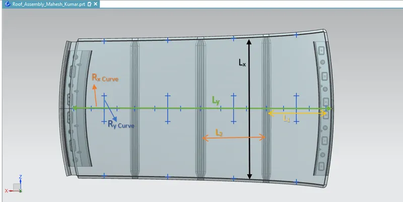
Taking values as shown above. Rx & Ry values should be considered as per condition, above image is for reference only.
After Appling Calculations:
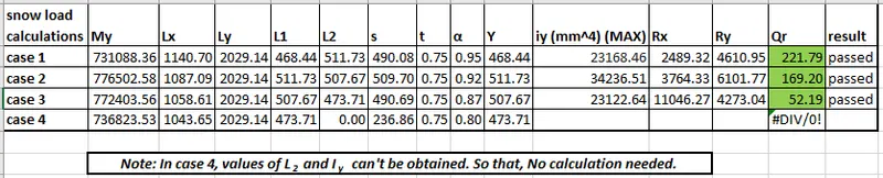
Image of Snow Load Calculation part
It appears that the values that have been acquired in Study 1 (Section modulus [MAX]) are QR > 3.1
Section analysis:
The quantity of deformation and deflection of a part can be predicted using the section moment of inertia. It is preferable to have a greater moment of inertia because it results in less deflection for a given force. The part's section inertia is increased by the part's width, as well as by the inclusion of flanges and embosses. Here, the master sections for the roof and roof rails are provided along with a section study.
BOW ROOF 1:
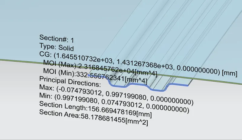
Moment of inertia maximum,( MAX) I max =2.316×10⁴ ( mm4)
Moment of inertia maximum ,( MIN) I min =332.556 ( mm4)
CENTER BOW ROOF:
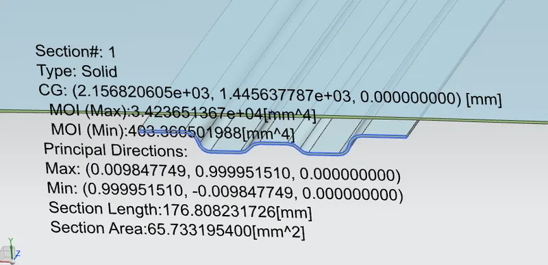
Moment of inertia maximum,( MAX) I max =3.423×10⁴ ( mm4)
Moment of inertia maximum ,( MIN) I min =403.360 ( mm4)
BOW ROOF 2:
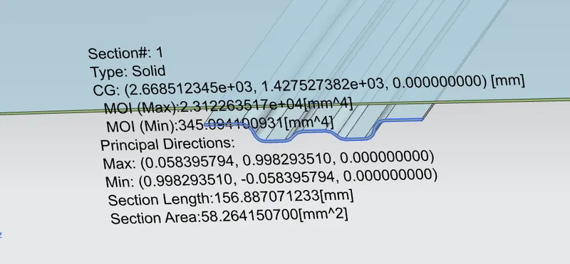
Moment of inertia maximum,( MAX) I max =2.312×10⁴ ( mm4)
Moment of inertia maximum ,( MIN) I min =345.094 ( mm4)
DRAFT ANALYSIS:
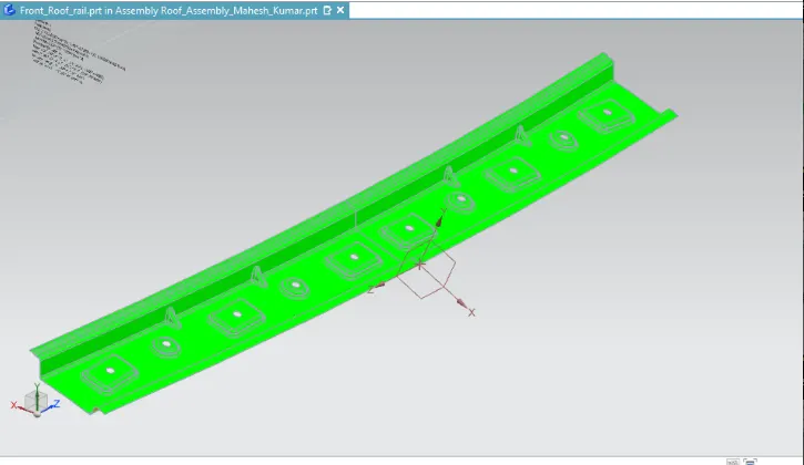
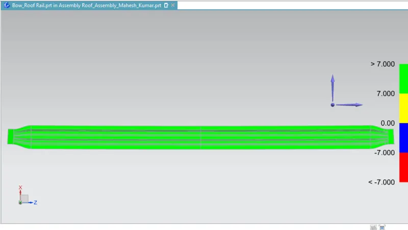
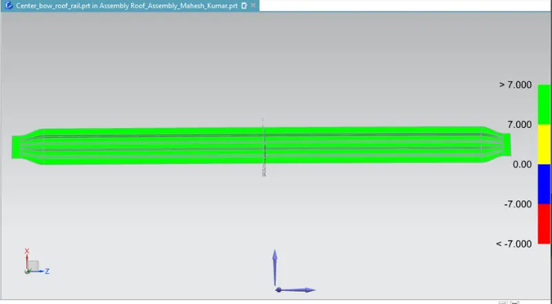
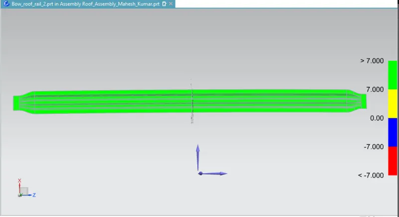
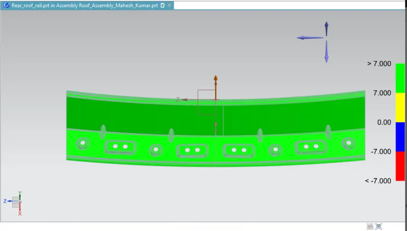
You can determine whether the portion you drafted will be simple to remove using the Draft Analysis command. In this kind of analysis, zones on the analysed element are identified by colour ranges where the deviation from the draught direction at any given location corresponds to predetermined values.
For research, a minimum draught angle of 70 is taken into account. Green indicates that a component has positive draught angle greater than 70 and has passed analysis when all of the parts are facing the tooling direction.
FRONT ROOF RAIL:
BOW ROOF RAIL 1:
CENTER ROOF RAIL:
BOW ROOF RAIL 2:
REAR ROOF RAIL:
Different Views of Roof:
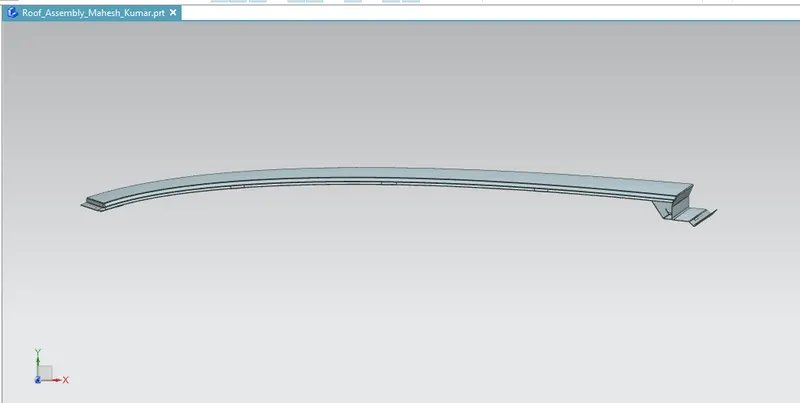
Side view of Roof assembly
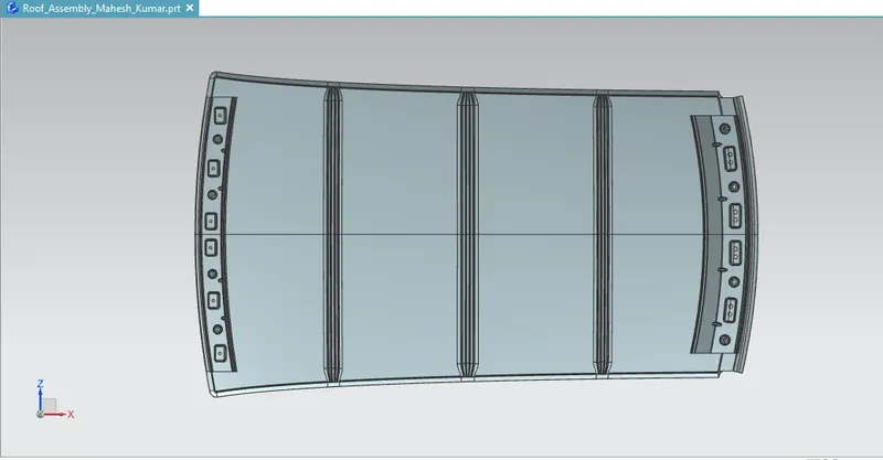
Bottom view of Roof assembly
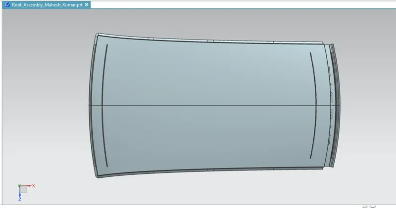
Top view of Roof assembly
Trimetric View
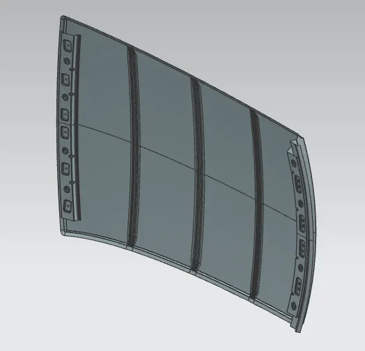
General View (Top-Backside)
CONCLUSION :
As a result, the roof, front roof rail, bow roof rails, central roof rail, and rear roof rail are built using the master sections, and moment of inertia and draught analysis are used to determine whether manufacturing is feasible.