Designing of Car Door Trim using CATIA V5 at OEM Standards.
Report on Development of a Door Trim panel
Creation of Door Trim Panel CAD model by following inputs as like in OEM and Tier1 companies
-
Introduction:
-
The purpose of this report is to outline the attachment strategy for the creation of a CAD model for the door panel in accordance with the practices followed by original equipment manufacturers (OEM) and tier 1 companies. The attachment strategy will consider the use of push pins with a dog house for lower substrate-door panel attachment, as well as heat stakes for part-to-part attachment.
- By using the provided Class-A surface, creating the Door Handle by Creating the tooling axis for the supplied Class-A Surface according to the draft angle specifications, and then doing the Draft analysis on the Part Body. Before creating a solid component it's always better to check the draft angle for the given Class A Surface.
-
-
Class A Surface: The door panel requires a Class A surface, which refers to the highest quality surface finish typically found in automotive exteriors. Class A surfaces are free from any visible defects and imperfections, providing an aesthetically pleasing appearance. The CAD model will incorporate the necessary design elements to achieve a Class A surface, ensuring the door panel meets the desired quality standards.
-
Nominal Thickness: To ensure accuracy and compatibility, the nominal thickness of the door panel will be referenced from the master sections. These master sections define the desired thickness of the door panel at specific locations. By adhering to the nominal thickness values provided in the master sections, the CAD model will accurately represent the physical door panel.
-
Attachment Strategy:
- Push Pin with Dog House for Lower Substrate: - Door Panel Attachment The lower substrate of the door panel will be attached using push pins with a dog house. This method provides a secure and reliable connection between the door panel and the lower substrate. The push pins are inserted into pre-drilled holes on the lower substrate, while the dog house allows for easy insertion and retention of the push pins. The CAD model will include the necessary features and dimensions to accommodate the push pins and dog house, ensuring proper alignment and attachment.
- Heat Stakes for Part-to-Part Attachment: Part-to-part attachment within the door panel assembly will be achieved using heat stakes. Heat stakes are plastic projections that are melted or formed to create a strong bond between two components. The CAD model will incorporate the appropriate heat stake features and locations, allowing for precise placement during the manufacturing process. The heat stakes will ensure the desired strength and stability of the attached parts within the door panel assembly.
- Push Pin with Dog House for Lower Substrate: - Door Panel Attachment The lower substrate of the door panel will be attached using push pins with a dog house. This method provides a secure and reliable connection between the door panel and the lower substrate. The push pins are inserted into pre-drilled holes on the lower substrate, while the dog house allows for easy insertion and retention of the push pins. The CAD model will include the necessary features and dimensions to accommodate the push pins and dog house, ensuring proper alignment and attachment.
- Conclusion:
- In conclusion the CAD model for the door panel will consider the attachment strategy commonly employed by OEM and tier 1 companies. The use of push pins with a dog house for lower substrate-door panel attachment and heat stakes for part-to-part attachment ensures the door panel's structural integrity and functionality. By adhering to the principles outlined in this report, the resulting CAD model will accurately represent the attachment strategy and contribute to the successful production of the door panel.
- Creating a surface model, doing a draught analysis, and developing a tooling axis are all crucial processes in the design of plastic components. Due to its ease of use and effectiveness, the bisecting method is a common way to create tooling axes. The end product will be of good quality, the manufacturing process will be effective, and the overall cost of production will be minimised if producers follow these processes.
- In conclusion the CAD model for the door panel will consider the attachment strategy commonly employed by OEM and tier 1 companies. The use of push pins with a dog house for lower substrate-door panel attachment and heat stakes for part-to-part attachment ensures the door panel's structural integrity and functionality. By adhering to the principles outlined in this report, the resulting CAD model will accurately represent the attachment strategy and contribute to the successful production of the door panel.
The first step in applying the bisecting approach in CATIA is to digitise the part using the software's surface modelling features. The part's symmetry plane is then identified, and a plane is made to bisect it perpendicular to that plane. Last but not least, the tool axis is positioned perpendicular to the plane that divides the mould, allowing the cutting tool to reach all required features without endangering the part or the tool.The Bisecting method provides for quick machining while ensuring that the finished product is of excellent quality, making it particularly helpful for symmetric items that need to be machined on both sides. By utilizing this technique in CATIA, manufacturers can reduce production time and costs while still producing high-quality plastic components that meet the required specifications.
TOOLING AXIS:
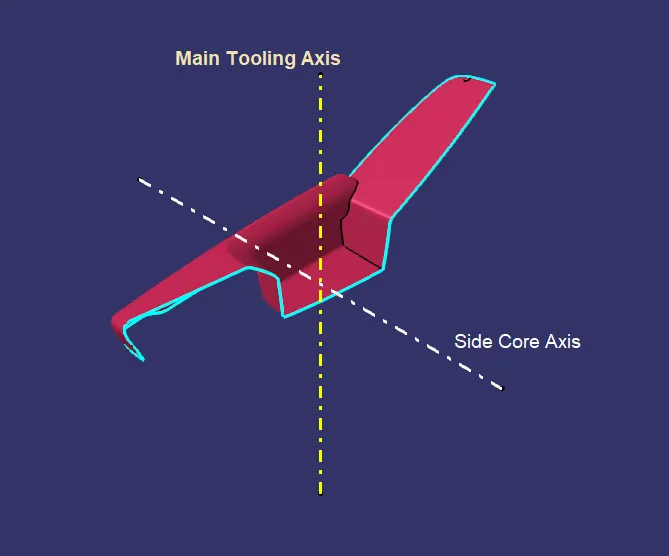
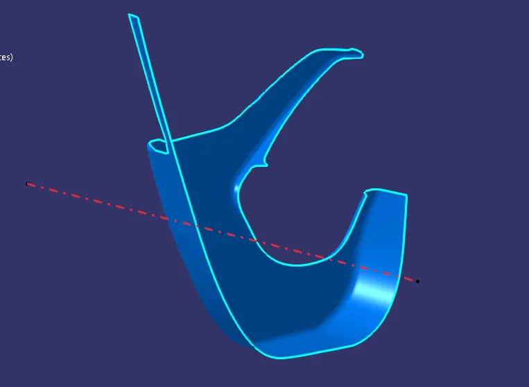
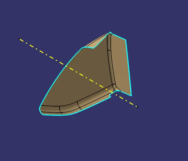
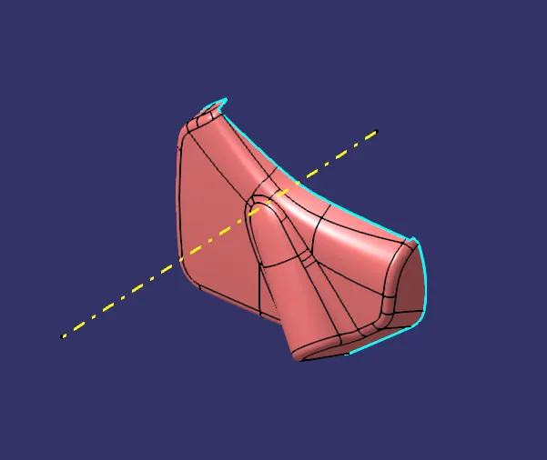
The plastic injection moulding process depends heavily on the tooling axis. It establishes the part's orientation within the mould, which has an impact on the end product's mechanical characteristics. The item's strength, longevity, and aesthetic appeal could be compromised by internal stresses, warping, or other problems brought on by improper tooling axis alignment. Additionally, a misaligned tooling axis may lead to increased tool wear, longer machining times, and higher costs. The tooling axis must be optimised if high-quality plastic components that comply with the necessary standards are to be produced at a cheaper cost.
The tooling axis also affects production costs and overall productivity. Manufacturers can cut the time and expense needed to make high-quality plastic components by designing the proper tooling axis. The main parts of the mould must be accessible by the cutting tool without endangering the tool itself. A cutting tool may successfully mill the mould with the help of a precisely aligned tooling axis, resulting in a shorter cycle time and less tool wear. Therefore, by optimizing the tooling axis, the entire cost of production can be reduced while guaranteeing that the finished product meets the necessary criteria.
Tooling Axis For the given Class A Surfaces of Door Trim Panel
1.1) Tooling Axis for Arm Rest Class-A Surface
1.2) Tooling Axis for Lower Substrate Class-A Surface
1.3) Tooling Axis for Map Pocket Class-A Surface
1.4) Tooling Axis for Bottle Holder Class-A Surface
DRAFT ANALYSIS:
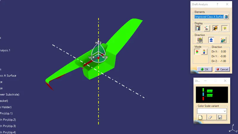
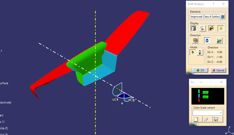
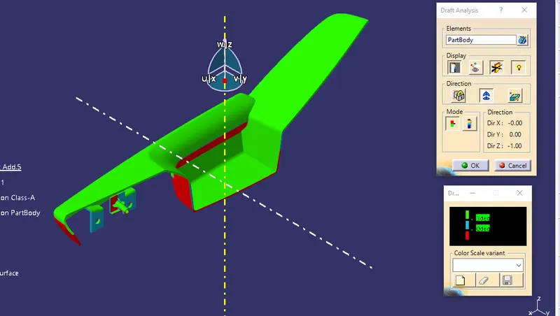
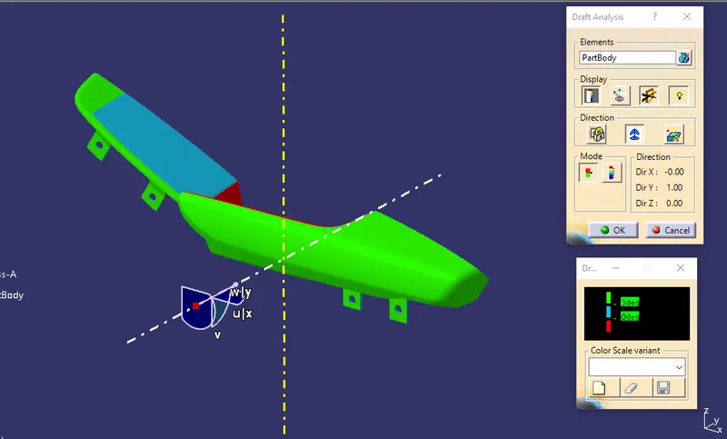
Draft analysis is a critical step in the plastic injection molding process that is essential for ensuring the production of high-quality plastic components. In the industrial sector, draft analysis is often referred to as parting line analysis, and it involves analyzing the 3D model of a plastic component to determine the optimal angle of the draft for the part.
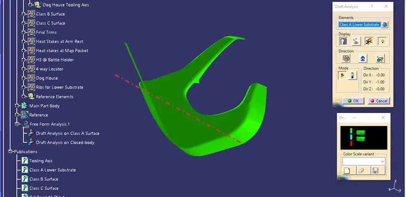
The draft angle, also known as the taper angle, is the degree to which the walls of the part are tapered to facilitate its removal from the mold after the plastic injection process. This is an important consideration in the design of plastic components, as it can affect the quality of the final product and the efficiency of the manufacturing process. The draft analysis process in CATIA involves analyzing the 3D model of the part to determine the optimal draft angle for each feature of the part. The software identifies any areas of the part where the draft is insufficient, and it suggests modifications to ensure that the part can be removed from the mold without damage.
By performing a draft analysis in CATIA, manufacturers can ensure that their plastic components are of high quality and can be produced efficiently. The software provides advanced simulation capabilities that allow designers to identify and correct any issues with the draft angle before production begins. This ensures that the final product meets the required specifications and that the manufacturing process is optimized for cost and efficiency.
Images of Draft Analysis of Door Trim parts in Different Orientations at Different Stages
1. Arm Rest
1.1 Class-A Surface Draft Analysis on Tooling Axis
1.2 Class-A Surface Draft Analysis on Side Core Axis
1.3 Part Body Draft Anaysis on Tooling Axis
1.4 Part Body Draft Anaysis on Side Core Axis
2.Lower Substrate
2.1) Draft Analysis on Class A Surface at Tooling Axis
2.2) Draft Analysis on Part Body at Toolng Axis
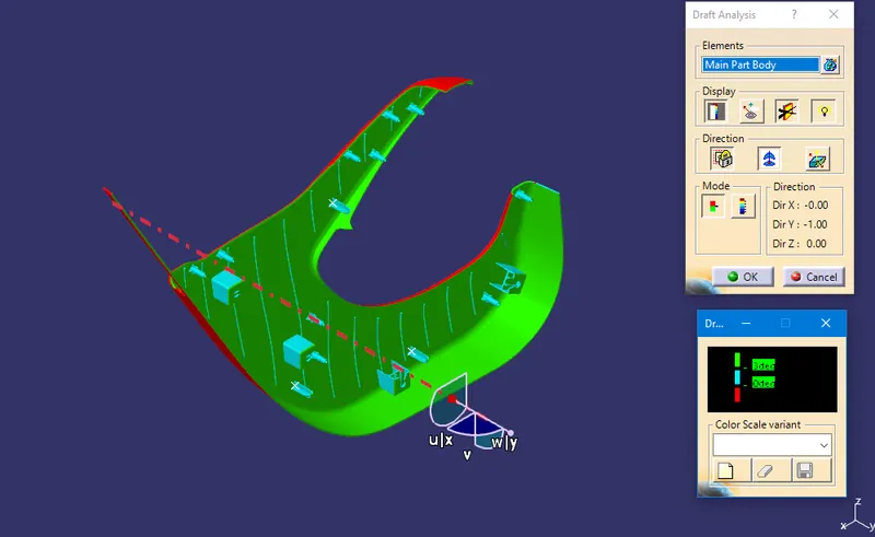
Note: Cyan Coloy is showing 0.5 deg draft angle that is show in next image.
2.3) Draft Analysis on Part Body at Toolng Axis
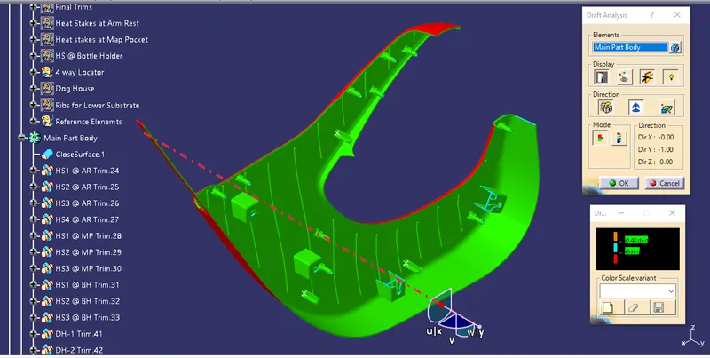
Note: Draft angle having more than 0.48Deg have been show in Green color
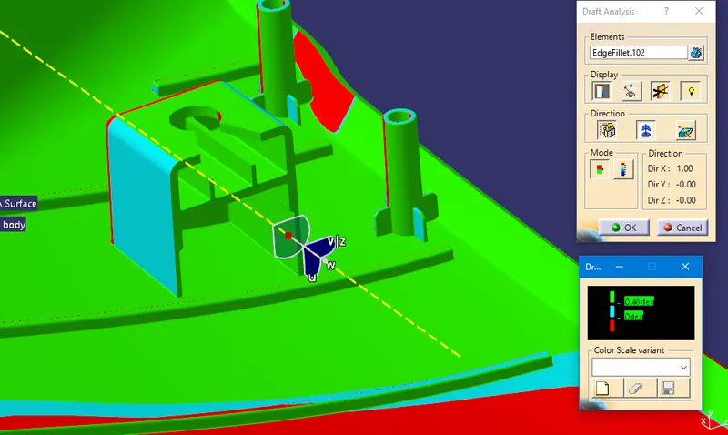
2.4) Draft Analysis on Dog House of Lower Substrate at Side Core Axis
3. Map Pocket
3.1) Class-A Draft Analysis at Tooling Axis
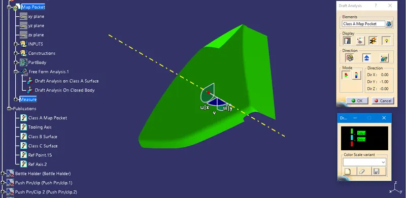
3.2) Draft Analysis on Part Body at Tooling Axis
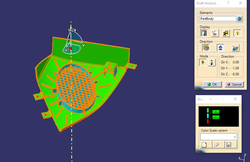
Note: Minimum Draft Angle of 0.5Deg has been maintained all over, Except Speaker area and its Mesh
3.3) Draft Analysis on Dog House of Map Pocket at Side Core Axis
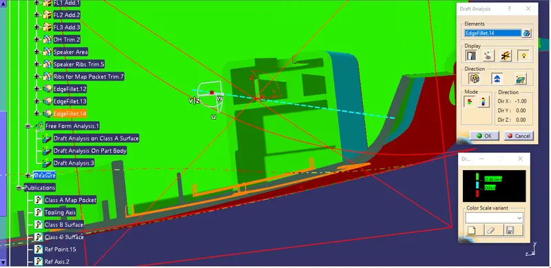
4. Bottle Holder
4.1) Draft Analysis on Class A Surface at Tooling Axis
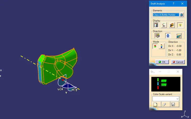
Note: Class-A Surface should be updated by Class-A Engineer as Cyan color is showing 0 deg Draft Angle
3.2) Draft Analysis on Part Body at Tooling Axis with Minimum Draft Angle.
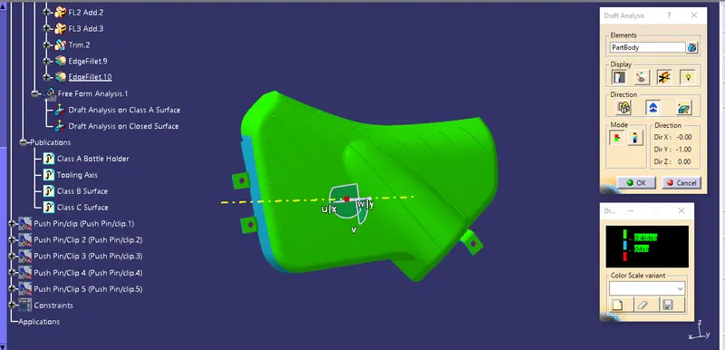
Note: Minimum Draft Angle has been maintained all over the Part Body
5. Push Pin
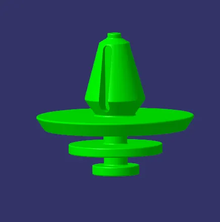
5.1) Image of Push Pin/Clip as given
Images of Door Trim Panel Assembly in Different Orientations
Door Trim Panel assembly Class A Surface View
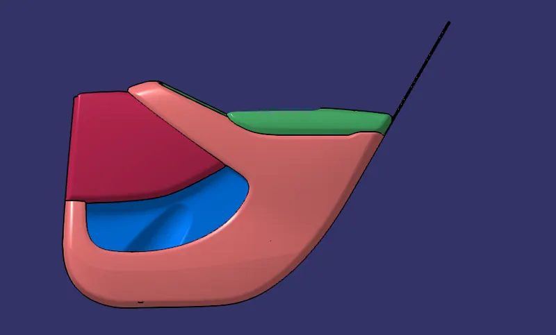
Door Trim Panel assembly Class B Surface View
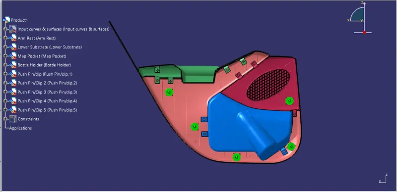
Image of zoom in version of Arm Rest in Door Trim Panel Assembly
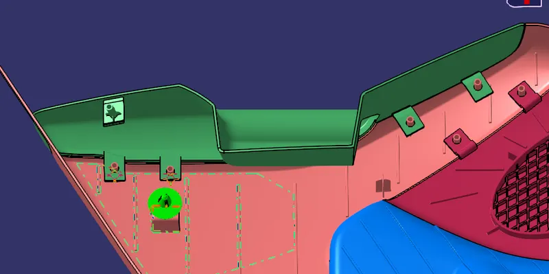
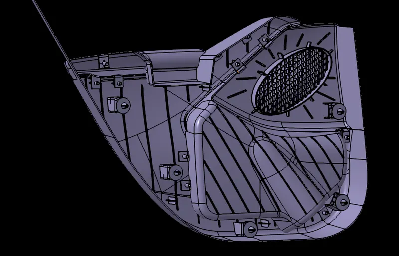
Image of zoom in version of Map Pocket in Door Trim Panel Assembly
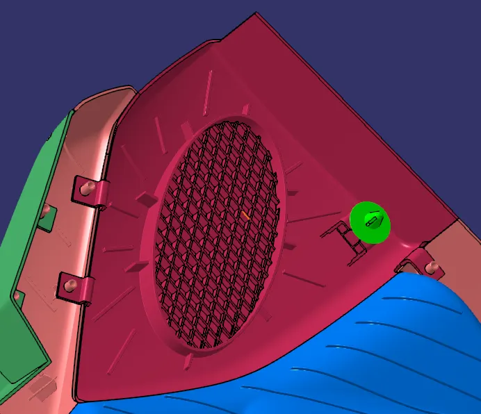
Image of zoom in version of Bottle holder in Door Trim Panel Assembly
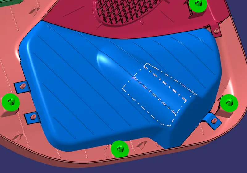
General Images of the Door Trim Assembly
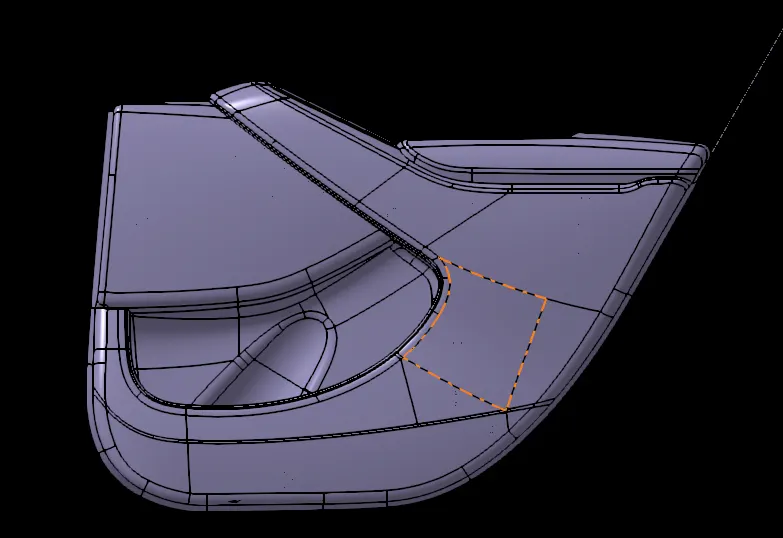
...................
Note: All the CATparts & CATproduct files have been uploaded in a ZIP folder and Attached.