Wiring harness design in CATIA V5 - 3D modeling Week 2 Challenge
Report for Defining Connectors and Cavity Clip using Electrical Part Design Workbench in CATIA V5
Introduction
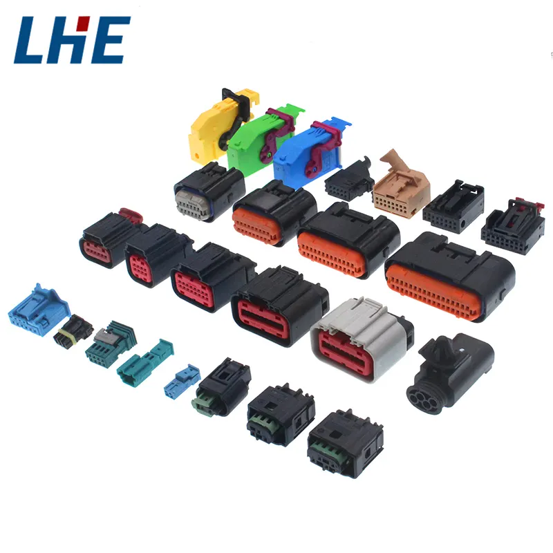
An electrical connector is an electro-mechanical device used to join Electrical termination and create an electric circuit. Electrical connectors consist of Housing, Terminals, Wedge Locks, Seals, Cavity, Mounting Cam, etc. Connectors are Plastic molded housing with locking & Retention features
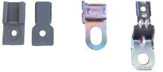
Clips & Clamps are used to Fix wiring harness bundles by providing positive fixings. Mounting Clips are used for supporting conduits. These clips are made of High-Quality Impact Resistant Polyamide. The mounting clips are stackable and are fixed with the help of screws onto the panel or equipment surface.
By downloading the .igs or .stp files from te.com we can work on 3D components like Connectors and Cavity Clip by importing them into CATIA V5 and defining them Electrically.
Given Data Links:
- Deutsch DT06 – 08SA ( https://www.te.com/usa-en/product-DT06-08SA.html)
- Tyco 174357-2 (https://www.te.com/usa-en/product-2-174357-2.html?source=header-match)
- Tyco 85229-1 – (https://www.te.com/usa-en/product-85229-1.html?q=85229&source=header)
By downloading the .igs or .stp files from te.com we can work on 3D components like Connectors and Cavity Clip by importing them into CATIA V5 and defining them Electrically.
General Steps that are involved in Defining a Connector as an Electrical Component in Wiring Harness Workbench
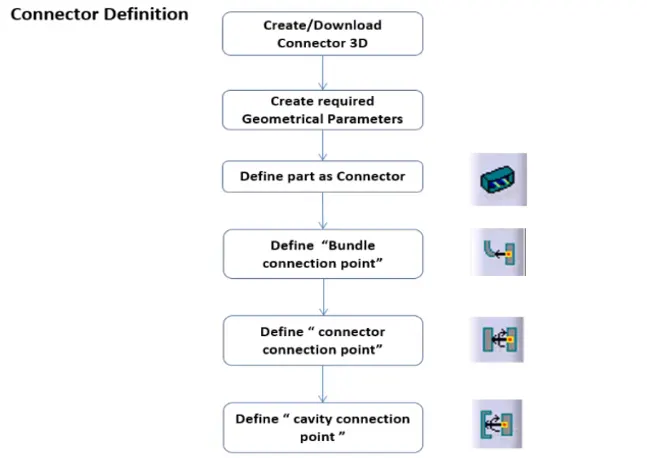
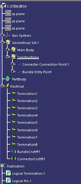
Steps that are followed to Define Deutsch DT06 – 08SA as Electrical Component:
- The 3D CAD data must first be opened in Catia before the file format (such as .igs or .stp) is changed to .CATPart.
- Next, in the Catia Part Design Workbench, specify the connector geometrically. To accomplish this, we must first assign a mid-point to the connector's bundle connection side face, then another mid-point to the connector's connector connection side, and last, we must assign an axis system to the mid-point of the connector's connector connection side face. This will enable us to determine the geometry of our connector properly.
- To define the connector electrically, start the Electrical Part Design Workbench in Catia.
- The define connector option is first selected from the toolbars, followed by the connector body and the assignment of the connector's terminal count, in this case, 8 terminals.
- We next choose the define bundle connection point option from the toolbars, the connector body, the bundle contact face for representation, the mid-point for the point, and once more the bundle contact face for the starting condition, and we click on okay.
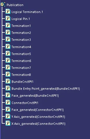
- Last but not least, we choose the "define connector connection point" option from the toolbars, then we choose the connector body, mid-point for representation, contact face for contact, Y-axis for coincidence, and X-axis for orientation, before clicking on "ok." This will give our connector a complete electrical definition.
- Make sure to save the file in the appropriate folder once the steps mentioned above have been finished.
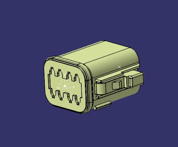
Images of Deutsch DT06 – 08SA with feature tree
3D Image of the Connector
Feature Tree Image 1
Steps that are followed to Define Tyco 174357-2 as Electrical Component:
- The 3D CAD data must first be opened in Catia before the file format (such as .igs or .stp) is changed to .CATPart file.
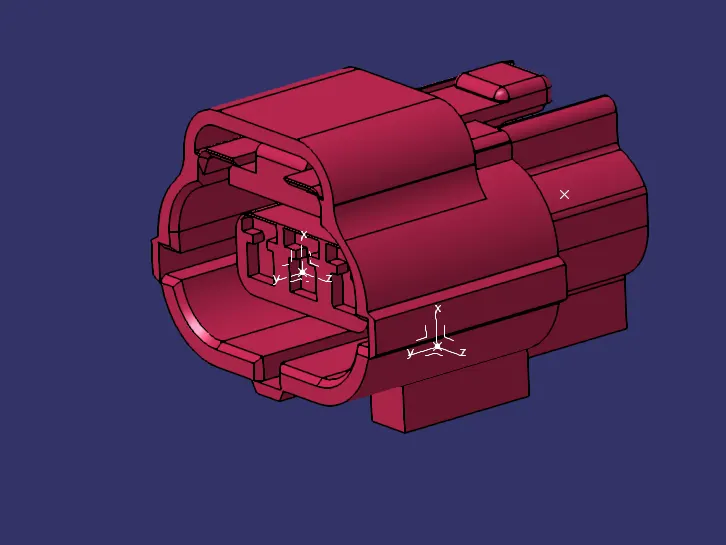
- Next, in the Catia Part Design Workbench, specify the connector geometrically. To accomplish this, we must first assign a mid-point to the connector's bundle connection side face, then another mid-point to the connector's connector connection side, and last, we must assign an axis system to the mid-point of the connector's connector connection side face.
To install a clip onto the connections, we must also make a mating reference on the bottom side of the connector. - On the face that will come into contact with the clip, we can simply establish a midpoint and an axis system using that midpoint as a reference. This will enable us to properly determine the geometry of our connector.
- To define the connector electrically, start the Electrical Part Design Workbench in Catia.
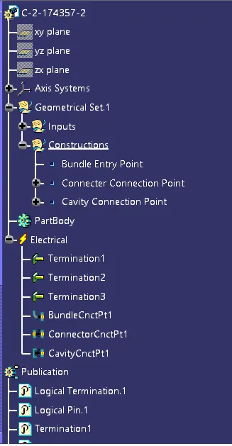
- The "define connector option" is first chosen from the toolbars, after which the connection body is chosen. Finally, the connector's three terminals are assigned.
- We next choose the define bundle connection point option from the toolbars, the connector body, the bundle contact face for representation, the mid-point for the point, and once more the bundle contact face for the starting condition, and we click on okay.
- Then, from the toolbars, we choose the define connector connection point option. Next, we choose the connector body, mid-point for representation, contact face for contact, Y-axis for coincidence, and X-axis for orientation. Finally, we click on OK.
- Then we choose the "define cavity connection point" option from the toolbars, choose the connector body, the midpoint of the bottom side as a representation, the mating face as the point of contact, the Y-axis as the coincidence, and the X-axis as the orientation, and finally click on "ok." This will give our connector a complete electrical definition.
- Make sure to save the file in the appropriate folder once the steps mentioned above have been finished.
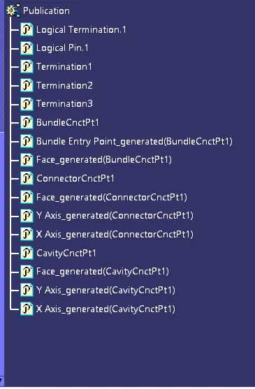
Images of Tyco 174357-2 with feature tree
3D Image of the Connector
Feature Tree Images
Steps that are followed to Define Tyco 85229-1 as Cavity Clip:
- The 3D CAD data must first be opened in Catia before the file format (such as .igs or .stp) is changed to .CATPart File.
- Then, in the Catia Part Design Workbench, specify the clip geometrically. To do this, we need just designate a midpoint on the face that will make contact with the connection, then use that midpoint as the reference point for an axis system. We will be able to fully define our clip geometrically as a result.
- To specify the clip electrically, start Catia's Electrical Part Design Workbench.
- The define mounting equipment option is first chosen from the toolbars, and then the clip is chosen.
- Following the selection of the "define cavity" option from the toolbars, we must also choose the clip body, mid-point for representation, contact face for contact, Y-axis for coincidence, and X-axis for orientation before clicking on "OK." This will give our connector a complete electrical definition.
- Make sure to save the file in the appropriate folder once the steps mentioned above have been finished.
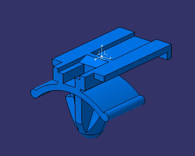
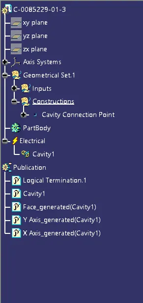
Images of Tyco 85229-1 with feature tree
3D Image of the Connector
Feature Tree Image
Assembly of the Tyco 174357-2 connector and Tyco 85229-1 Cavity Clip
- Launch Catia's Assembly Design Workbench. In the assembly tree, duplicate the connector and clip pieces, and paste them. Give both models an appropriate orientation so that they can come into proper contact by rotating them.
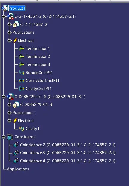
- Launch Catia's Electrical Assembly Design Workbench. To mount the devices together, choose the connector and clip from the toolbars' connect electrical devices option.
- Make sure to save them in the required folder.
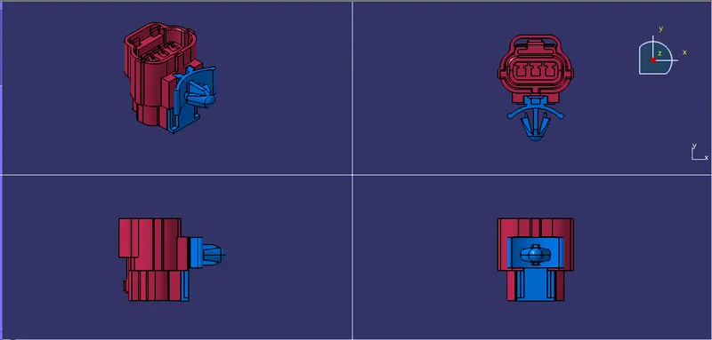
Images of Assembly of Tyco 174357-2 connector and Tyco 85229-1 Cavity Clip
3D Image of the Assembly
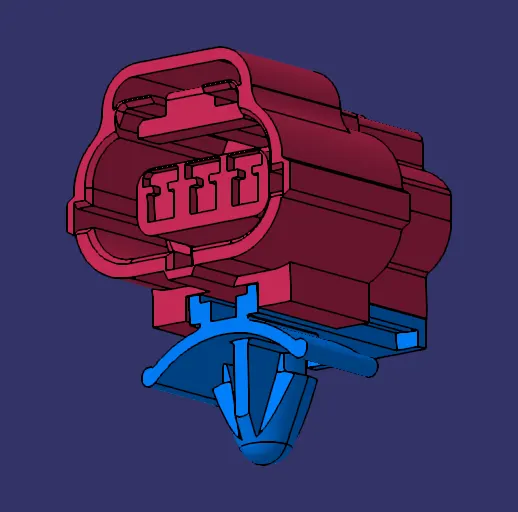
3D Image of the Assembly 2
Feature Tree Image
..................
NOTE_1: .igs files are imported to define the components so that all the components have surface bodies only not solid bodies. If .stp files were considered it would be solid files.
NOTE_2: All the files have been uploaded as a Single ZIP file and attached.