Week 10 - Challenge 2- Attachment Feature Creation (Dog House)
REPORT ON DOOR TRIM - DOG HOUSE
By using the provided Class-A surface, creating the Door Handle by Creating the tooling axis for the supplied Class-A Surface according to the draft angle specifications, and then doing the Draft analysis on the Part Body. Before creating a solid component it's always better to check the draft angle for the given Class A Surface.
CAD software like CATIA creates a surface model of the desired final shape when designing plastic components. The following steps are often included in the process:
- Identify the component's purpose, as well as its size, shape, material, and any other important criteria, to define the component's needs.
- Create a digital surface model of the component using CATIA software, including all the necessary details including holes, ribs, bosses, and other design aspects. A series of mathematically defined curves and surfaces are used to generate the surface model, a smooth and exact representation of the final design.
- Performing draft analysis: This involves analyzing the surface model to determine the optimal angle of the draft for the part, which is the degree to which the walls of the part are tapered to facilitate its removal from the mold after the plastic injection process. This is an essential step that ensures that the final product is of high quality, and the manufacturing process is efficient.
- Creation of tooling axis: This involves creating a path for the cutting tool that will be used to machine the mold for the component. The tooling axis determines the quality of the final product, the efficiency of the machining process, and the overall cost of production.
The tooling axis can be created using various methods, including the Bisecting method. The Bisecting method is a simple and efficient tooling axis creation method that involves creating a plane that bisects the part and aligning the tool axis perpendicular to that plane. This method is commonly used for symmetric parts that require machining on both sides. The process involves creating a surface model of the part using CATIA software, determining the symmetry plane of the part, creating a plane that bisects the part perpendicular to the symmetry plane, and aligning the tool axis perpendicular to the bisecting plane.
In conclusion, designing plastic components involves several critical steps, including creating a surface model, performing draft analysis, and creating a tooling axis. The Bisecting method is a popular tooling axis creation method that is widely used due to its simplicity and efficiency. By following these steps, manufacturers can ensure that the final product is of high quality, the manufacturing process is efficient, and the overall cost of production is optimized.
TOOLING AXIS:
The tooling axis is crucial to the plastic injection molding process. It determines the part's orientation within the mold, which affects the mechanical properties of the finished product. Internal strains, warping, or other issues caused by incorrect tooling axis alignment may compromise the item's strength, durability, and aesthetic appeal. A misaligned tooling axis may also result in greater tool wear, extended machining times, and increased costs. In order to produce high-quality plastic components that adhere to the appropriate standards while lowering production costs, it is imperative to optimize the tooling axis.
Overall productivity and production costs are also impacted by the tooling axis. By creating the appropriate tooling axis, manufacturers may reduce the time and cost necessary to produce high-quality plastic components. The cutting tool must be able to access the mold's key components without risking the part of the tool. With the aid of a perfectly aligned tooling axis, a cutting tool may successfully mill the mold, resulting in a quicker cycle time and less tool wear. Therefore, the overall cost of production can be decreased while ensuring that the finished product fulfills the required standards by optimizing the tooling axis.
BISECTING METHOD: In the plastic injection molding business, the bisecting method is a widely used method for producing a tooling axis for symmetric pieces. The process entails drawing a plane that cuts the part in half and setting the tool axis so that it is perpendicular to the plane. This strategy is straightforward and effective, which makes it a desirable choice for enterprises trying to improve their production process.
To apply the Bisecting method in CATIA, the first step is to create a digital model of the part using the software's surface modeling capabilities. The symmetry plane of the part is then determined, and a plane is created that bisects the part perpendicular to the symmetry plane. Finally, the tool axis is aligned perpendicular to the bisecting plane, ensuring that the cutting tool can access all the necessary features of the mold without damaging the part or the tool itself. The Bisecting method is especially useful for symmetric parts that require machining on both sides, as it allows for efficient machining while ensuring that the final product is of high quality. By utilizing this technique in CATIA, manufacturers can reduce production time and costs while still producing high-quality plastic components that meet the required specifications.
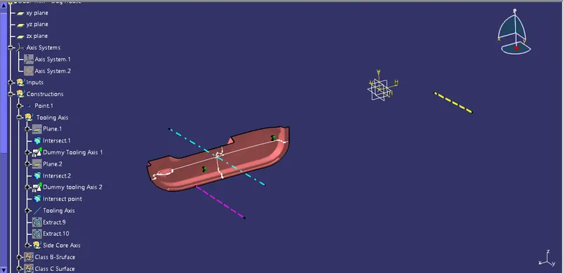
Steps that have been followed to Create the Tooling Axis
- Create intersections on Class-A Surface using Planes in different directions.
- Then find the lines that can be found as the same on both sides and try to create lines in a sketch. (This can be found mostly in symmetric parts.)
- Now create a bisecting Line & make all other drawings into construction mode.
- Do the same for both intersections.
- To create the Tooling axis using bisecting method we have to analyze the best tooling direction first and then we have to create the point where the tooling axis is needed.
- Create a Point by using both intersections, so that we can create a point for the Tooling axis.
- After that, Create a Dummy Tooling Axis 1 and 2(Yellow Axis Line and Pink Axis Line) with the help of intersecting lines on the surface.
- Finally by using both lines create the Tooling Axis (Cyan Axis Line) with the help of bisecting option in line Command.
- Additionally we have to create Side Core Axis for Dog House creation by using same method.
DRAFT ANALYSIS:
Draft analysis is a critical step in the plastic injection molding process that is essential for ensuring the production of high-quality plastic components. In the industrial sector, draft analysis is often referred to as parting line analysis, and it involves analyzing the 3D model of a plastic component to determine the optimal angle of the draft for the part.
The draft angle, also known as the taper angle, is the degree to which the walls of the part are tapered to facilitate its removal from the mold after the plastic injection process. This is an important consideration in the design of plastic components, as it can affect the quality of the final product and the efficiency of the manufacturing process. The draft analysis process in CATIA involves analyzing the 3D model of the part to determine the optimal draft angle for each feature of the part. The software identifies any areas of the part where the draft is insufficient, and it suggests modifications to ensure that the part can be removed from the mold without damage.
By performing a draft analysis in CATIA, manufacturers can ensure that their plastic components are of high quality and can be produced efficiently. The software provides advanced simulation capabilities that allow designers to identify and correct any issues with the draft angle before production begins. This ensures that the final product meets the required specifications and that the manufacturing process is optimized for cost and efficiency.
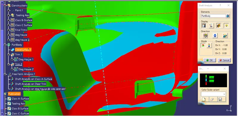
Images of Draft Analysis of Door Trim in Different Orientations at Different Stages
Draft Analysis on Class A-Surface
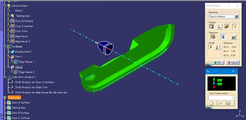
Draft analysis on Door Trim (View 1)
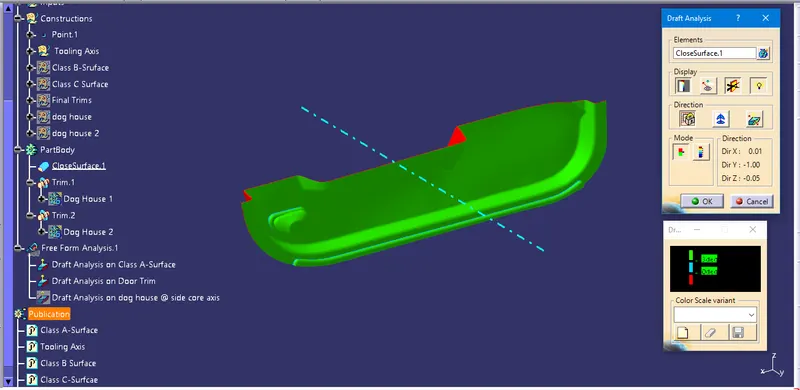
Draft analysis on Door Trim (View 2)
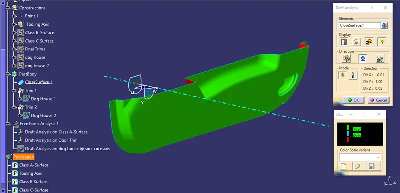
Draft Analysis for Dog House at Side Core Axis
Design Rules Carried out to Create Dog House
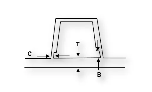
General Guidelines carried out designing for Dog House:
-
Doghouse wall thickness at the intersection of the part wall ( C ) should be 40% or less than the main wall stock ( T ).
-
The height of ( B ) should be between 3.0 – 6.0 mm
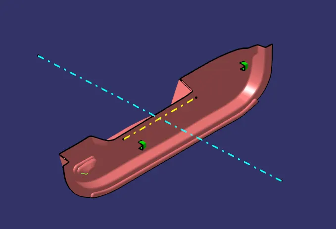
Images of Part Body in Different Orientations
Isometric View
Front View
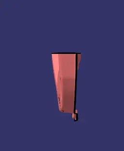
Left Side View
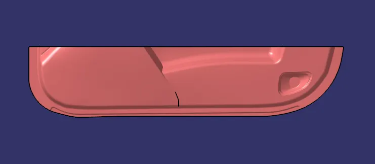
Right Side View
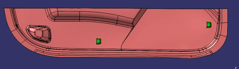
Top View

....................
NOTE: CATpart has been uploaded as a Single ZIP File.