Week 3:- BiW Fixture Design Methodologies Challenges
Week 3:- BiW Fixture Design Methodologies Challenges
Q1. What is Design Methodology?
ANS: Design Methodology is nothing but the steps followed during the concept designing stages of Fixtures design.
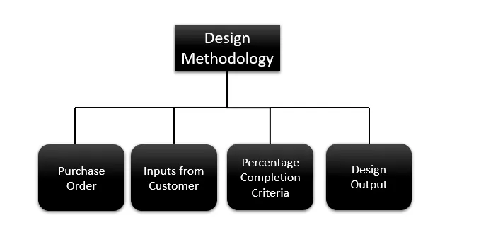
The systematic approach and guiding concepts used in developing and creating fixtures for the Body-in-White stage of vehicle manufacture are referred to as design methodology in BIW fittings. By using this system, it is ensured that the fixtures are made to hold various car parts securely while they are being welded, assembled, and inspected.
- Purchase order: Purchase order is the order given from the customer to start the work.
- Inputs from Customer: It includes information on the following topics: functional requirements, preferred standard components, automobile products, layout, ergo data, weld study and standard detailing templates.
- Percentage Completion Criteria: To monitor the progress of the process, it is followed during the designing and shipment phases of the welding fixtures.
- Design Output: The output is 3D models and the 2D drawings of the tools. Unitized tools:(multiple units on a common base) require two types of drawing sheets Key sheet and Layout Sheet. Non-unitized tools: Tools that can stand alone and can be detailed completely on a layout sheet.
........................................................
Q2. What are the inputs required from the customer to start designing a Fixture?
ANS: The Inputs reqiued form the customer are mentioned below
-
- Functional Requirements: It contains data about how and where the arrangements of Welding Fixture, Hemming Fixture, Checking Fixture and Storage Racks are done in the Plant/Industry.
- Preferred Standard Components: As is common knowledge, different businesses follow to various standards. We shall adhere to the standards set by our clients. By adhering to the standards when designing and producing parts, we will save time and money, which will naturally shorten the length of the projects. The cost can be decreased by simply replacing the standard parts from the old fixture with the new fixture.
The following list includes some of the preferred standard components used in BIW:
- Standards like ABB, NAAMS(North American Association for Mechanical Standards), DESTACO, ZYTRAN, TUNKERS.
- Standard Parts like Risers, L-Blocks, Retainers, Pins.
- Components like Clamps, Cylinders, Slides, Switches, Sensors.
- Weld guns, Tip Dressers, Tool changers. Tip Dressers are used to sharpen the tip of the tools which are used in robots in various process.
- Car Products: Car Products Include the details of the following
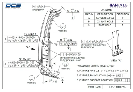
- GD&T :GD&T Provides information of, Locating pins, Rest, Clamp, Dumps & Slide information of each Station. Sequence of opening of clamps, dumps & Slide stroke information.
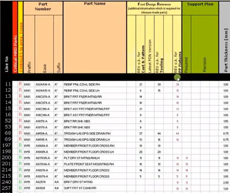
- Part Lists: It provides lists of the components that will be put together in the fixture. The list includes details such as component name, part thickness, fixture revision, part number, etc.
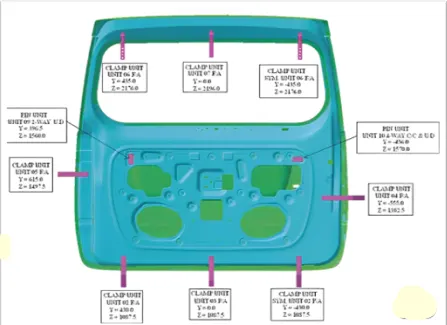
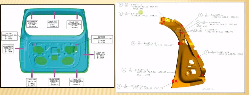
- Clamp plan: The pin, rest, clamp, and dump locations are all detailed in the clamp plan. It is a crucial piece of client feedback. It is not acceptable to alter the clamp plan or position without the customer's consent.
- 3D CAD file: The purchaser will receive the 3D model of the automobile component. We will construct our fixture design process using that 3D model. The 3D CAD file will be in either IGES (.igs) or STEP (.stp) format.
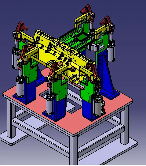
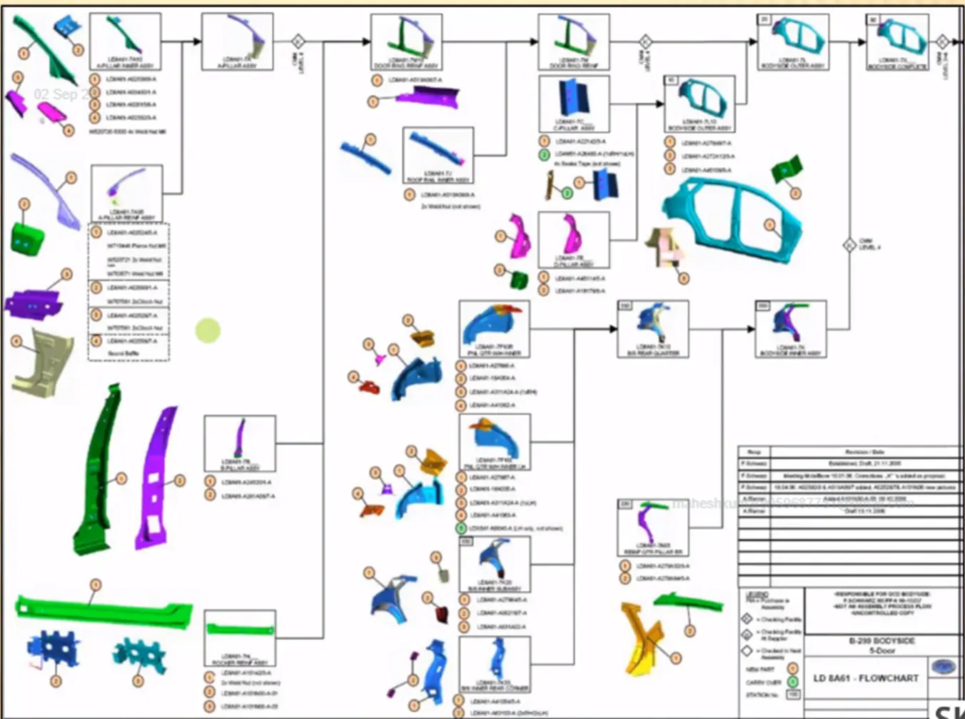
- Product assembly process sheet: It provides details on the stages of the assembly process, including how the parts migrate from one assembly step to another when the joining procedure is finished.
- GD&T :GD&T Provides information of, Locating pins, Rest, Clamp, Dumps & Slide information of each Station. Sequence of opening of clamps, dumps & Slide stroke information.
- Layout: Layout Provides information about the following like Flow of parts, Station Pitch, Robot Stations, Accessories like Tool changer and tip dresser, Sub assembly links, Platform height, Loading/Unloading Sequence/heights.
- Ergo Data: Ergonomics refers to the study of human behavior & Movements and also Ergo data Provides information of Loading height ,working safety zone of operator etc.
- Weld Study: Weld Study includes Weld gun Details and also Weld Matrix, Weld Points, Geo Weld Points and Re-spot Weld Points
- Standard Detailing Templates: These inputs contain 2D CAD drawing detailed templates that adhere to customer standards.So, in order to meet consumer standards, we must adhere to the detailing templates.
...............................................................
Q3. What is the input we get from "Car Products"?
ANS:
INPUT WE GET FROM CAR PRODUCTS
- GD&T.
- Part lists.
- 3D CAD file.
- Clamp plan.
- Product assembly process sheet.
GD&T
- GD&T – Geometric Dimensioning & Tolerance.
- It provides information of locating pins, rest, clamp, damp & slide unit information of each station.
- Also includes the information of sequence of openings of clamps, dumps & slide stroke information.
TOLERANCE IMPORTANCE
- ASSEMBLIES: If two components dimensions do not fall within a predetermined range of values, they will frequently fit together.
- INTERCHANGEABILITY : If a replacement part is used, it must, within a set of tolerances, be an exact replica of the original part. From portion to part, an object's usefulness and size or shape have different relationships.
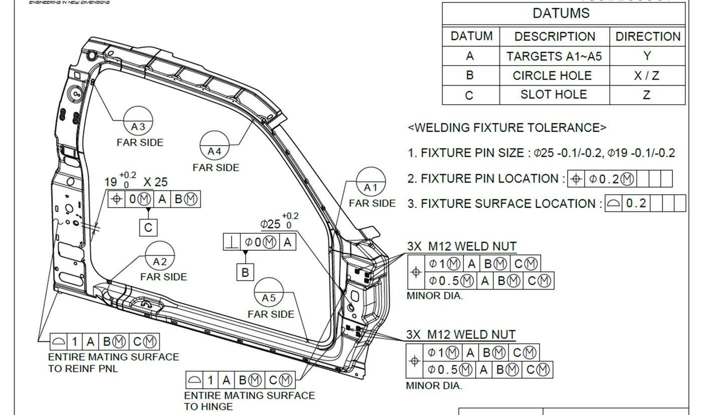
Use of GD&T
- Used when part features are critical to a function or interchangeability.
- When functional gaging is desirable and also when standard interpretation or tolerance is not already implied.
- When it allows a better choice of machining processes to be made for production of a part.
PART LIST
- It gives the lists of parts which are going to assembled in the fixture.
- The list contains the information of part number, part name, revision of fixture, part thickness, etc.
CLAMP PLAN
- The pin, rest, clamp, dump, and other locations are specified in the clamp plan.
- It is a crucial piece of client feedback. It is not recommended to alter the clamp plan or position without consulting the customers.
- It provides information on the precise location of the clamping units.
3D CAD FILE
- The customer will provide the 3D model of the automobile component.We will construct our fixture design process using that 3D model.
- The 3D CAD file will often be in the step file (stp), IGES file (igs), or part file (prt) formats.PRODUCT ASSEMBLY PROCESS SHEET
The material offered provides useful information about the post-joining steps of the assembly process. Once the initial joining phase has been completely finished, it focuses the complex transfer of parts from one assembly to another. In addition, it specifies the exact order in which components will be attached to the panel as well as the detailed sequence of actions required for the completion of a particular portion or panel. Also, this tool acts as an extensive guide that enables us to identify the continuing procedures that must continue without pause in order to give the part its final shape.
..................................................................................
Q4. What is the Clamp plan?
ANS:
A clamp plan is primarily used in the design of BIW fixtures to guarantee that body panels or other components are kept precisely and firmly in place during welding or assembly processes. This aids in maintaining the body structure's dimensional precision and alignment, which are crucial for guaranteeing the quality and safety of the finished product.
A typical clamp plan includes information such as:
-
Clamp Locations: It indicates the precise locations on the body parts to which clamps or fittings will be fastened. In order to assure perfect alignment and dimensional accuracy, these spots were carefully selected.
-
Clamp Types: It details the types of fittings or clamps that should be utilized at each site. Depending on the needs of the assembly process, various clamp types, such as pneumatic clamps, hydraulic clamps, or manual clamps, may be employed.
-
Clamp Forces: The design may also specify the clamping pressures or forces to be used on each clamp. In order to hold the components firmly without producing deformation, the appropriate clamping force is crucial.
-
Sequence of Clamping: It explains the sequence in which clamps should be tightened or loosened during the welding or assembling process. To make sure that parts are correctly positioned and fastened in the right order, this arrangement is essential.
-
Safety Considerations: Safety comes first when designing fixtures. The clamp strategy could include operator safety precautions like making sure clamps are locked in place before welding starts.
-
Tolerance Requirements: It could include tolerance parameters for component alignment and placement. To achieve design requirements, certain tolerances must be maintained.
An image of Clamp Units holding a BIW of the car backdoor
In summary, a well-designed clamp plan is essential for the design of BIW fixtures since it aids in the quick and precise assembly of automobile body parts, which eventually produces finished vehicles of high quality. It assists in lowering manufacturing flaws, enhancing production effectiveness, and guaranteeing that the finished product complies with design and safety criteria.
..........................................................
Q5. What is the purpose of a Layout?
ANS:
In BIW manufacturing or assembly facilities, a layout refers to the thoughtful arranging and positioning of fixtures, machinery, and workstations. Its many-faceted goals cover a number of essential duties, such as:
-
Flow of Parts: Creating a layout that allows for the efficient and well-organized manufacture of goods while allowing for the smooth movement of parts and materials across the facility.
-
Station Pitch: Determining out the best locations and distances between workstations to encourage efficient operations, reduce traffic, and boost productivity.
-
Robot Stations: To increase accuracy and efficiency, designate certain locations in the layout for robotic workstations, which execute automated tasks.
-
Accessories like Tool Changer and Tip Dresser: Giving particular locations for necessary equipment like tool changers and tip dressers to facilitate access and integration into the manufacturing process.
-
Subassembly Links: By adding subassembly stations or links within the layout, the production process can be made more efficient by effectively assembling and connecting components before final assembly.
-
Platform Height: Platform heights should be carefully chosen to maximize worker ergonomics, reduce physical stress and tiredness, and create a secure and comfortable work environment.
-
Loading/Unloading Sequence/Heights: Defining a schedule and heights for loading and unloading materials and components at different manufacturing stages in order to reduce handling and increase efficiency in operations.
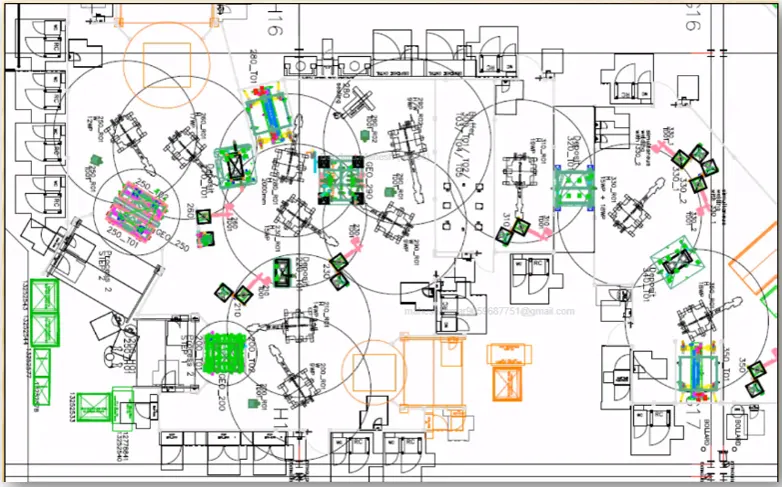
Layout example is shown above.
In summary, a well-designed plant layout takes into account these crucial tasks to build a structured, effective, and secure manufacturing environment, enhancing production processes and overall operational effectiveness.
..........................................................
Q6. What is Ergo data?
ANS:
Ergonomic data or information that is pertinent to the design and setup of fixtures to create a comfortable and secure working environment for operators is commonly referred to as "ergo data" in the manufacturing of BIW (Body-in-White) fixtures. In order to avoid worker pain, fatigue, and injury as well as to maximize the effectiveness and caliber of production operations, ergonomic considerations in BIW fixture manufacturing are essential.
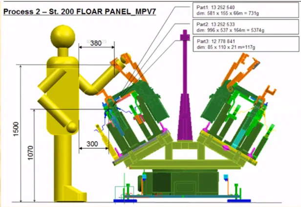
Ergo data may include:
-
Operator Anthropometry: The information on the operators' physical characteristics, such as height, reach, and body measurements, must be gathered in order to do this. This information aids in creating workstations and furnishings that are customized to the unique requirements and comfort of the employees.
-
Reach Zones: Locating the locations in a workstation where users must reach for tools, components, or controls. Ergo data assists in deciding where these items should be placed in order to avoid strain and unnecessary reaching.
-
Work Surface Heights: Establishing the ideal working heights for fixtures and workstations to enable operators to carry out operations comfortably and without having to bend over or stretch too much.
-
Tool and Equipment Design: Analyzing the ergonomics and design of manufacturing-related tools and equipment. Ergo, data can be used to direct the choice or creation of tools that are simple to use and handle.
-
Posture Analysis: Analyzing the physical positions that operators will take while using fixtures. This analysis aids in the design of furnishings that encourage ergonomically and neutrally sound postures to prevent problems with the muscles and joints.
-
Material Handling: Evaluating how users of the fixture will handle supplies, parts, and final goods. Fixtures that limit lifting, carrying, and reaching can be designed with the aid of ergo data, lowering the risk of injuries.
-
Safety Considerations: Ensuring that fixtures with ergonomic design also have safety measures and guidelines, reducing mishaps and injuries while in use.
Manufacturers may produce BIW fixtures that not only enhance production processes but also put the health and safety of their employees first by adding ergo data into the design process. With this strategy, productivity goes up, injury-related absences go down, and manufacturing quality gets better all around.
....................................................................
Q7. What do you understand by Weld study?
ANS:
The term "weld study" describes a methodical, in-depth inspection and analysis of the welding procedures and welded connections used in the manufacture of vehicle bodywork. In BIW manufacturing, a weld study's main goal is to guarantee the quality, integrity, and dependability of the welds used to unite different parts of the vehicle's body.
Weld Study includes the following
- <!-- [if !supportLists]-->Weld gun Details: This component of the study involves a detailed analysis of the welding equipment, specifically the weld guns used in the welding process. It includes information about the type of weld guns, their specifications, and their condition. Assessing weld gun details is crucial to ensuring that the equipment is in proper working order and capable of consistently producing quality welds.
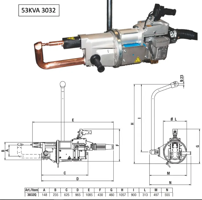
- Weld Matrix & Weld: The weld matrix is a critical aspect of the study that outlines the specific welds required for joining various components in the BIW assembly. This matrix includes essential data such as the location of welds, weld types (e.g., spot welds, seam welds), and the parameters used for each weld, including current, voltage, and timing. This catagory is classified into
- Geo Weld Points: Geo weld points refer to the geometric locations or coordinates of welds within the BIW assembly. These points are typically defined in relation to a reference coordinate system. Examining geo weld points is essential for precise placement and alignment of welds, which is critical for maintaining dimensional accuracy and structural integrity in the final assembly.
- Re-spot Weld Points: Re-spot weld points are specific locations within the BIW assembly where additional welding is required due to factors such as initial welds or adjustments during the manufacturing process which provides more stability and endurance for the BIW fixture. Identifying and documenting re-spot weld points is crucial to ensure that any necessary corrective actions need to be taken to meet quality standards.
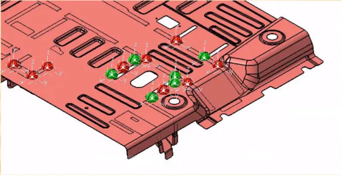
In the above image Weld Matrix is shown which includes Geo & Respot weld points
Geo spots — Red
Re-spots — Green
....................................................................
Q8. What are the criteria for percentage completion in the designing stage? Explain it in detail.
ANS:
Percentage completion criteria is followed in the designing stages and dispatch stages of the welding fixtures. Certainly, here's an explanation of each stage in the welding fixture design process, along with the corresponding percentage completion criteria:
-
0% to 25% - Input and Concept Design:
- Description: The process of designing welding fixtures is still in the beginning stages at this point. Customer inputs, requirements, and specifications are gathered by designers. The structure and operation of the fixture are generally conceptualized.
- Activities: In this phase, major design considerations are identified and early sketching and conceptualizing are done.
- Goals: The design team should have a comprehensive understanding of the project requirements and initial suggestions for the welding fixture at the end of this stage.
-
25% to 40% - Concept Approval and Simulation Check:
- Description: The design concepts created in the earlier stage are improved upon and reviewed during this step. To determine the sustainability of conceptual designs, simulation and analysis are used.
- Activities: Simulators or prototypes are used to verify the design's viability and functionality once detailed design concepts have been developed.
- Goals: By the end of this stage, the design team should have approved concepts ready for further development, with confidence in their feasibility.
-
40% to 85% - Design Freezing and Detailing:
- Description: The important phase is where the last details and improvements to the selected design concepts are made. The welding fixture is precisely designed down to the individual dimensions, materials, and manufacturing requirements.
- Activities: Detailed drawings, specifications, and plans are created for every component of the welding fixture. Prototypes may be built and tested.
- Goals: The design should be finalized by this point, which means that no major modifications or revisions are expected. The fixture design is almost finished ready for manufacturing.
-
85% to 100% - Check and Final Dispatch:
- Description: The final step involves thorough quality checks and inspections of the finished welding fixture design. After addressing any outstanding problems or mistakes, the fixture is ready to be sent to the production or assembly line.
- Activities: Comprehensive quality assurance inspections are carried out, including functionality tests and conformance with design and safety standards. Finalized production and assembly documentation is available.
- Goals: The welding fixture design needs to be fully validated at this point, agree with all specifications, and should be ready for use in the manufacturing process.
Assuring an organized and systematic method to welding fixture design, these steps and their corresponding completion criteria serve to ensure quality, effectiveness, and consistency throughout the design process.
..........................................................................
Q9. Brief about "Output" in design?
ANS:
It is the final stage in Design methodology. This stage deals with the output of 3D models and the 2D drawings of the tools used for BIW manufacturing.
- Unitized Tools: (multiple units on a common base) require two types of drawing sheets.
- Key sheet - An index of units and their placements on the tool base.
- Layout Sheet - A detailed drawing of individual units to include all of their components.
- Non-Unitized Tools: Tools that can stand alone and can be detailed completely on a layout sheet.
The output should compile following points:
- Approved standard components are to be used wherever possible.
- Design must be as simple and economical as possible.
- Design must comply with all current safety and ergonomic requirements.
- Design must provide for controlled and damage free handling of product.
- Adequate error proofing provision must be incorporated into each design by providing Proximity switches, Rough locators etc.
- The weight of the moving parts must be kept to a minimum while maintaining maximum strength.
- Frames and structures are to be simple and sturdy.
- Design clearance and accessibility for routhe maintenance and service.
- Motion control must be considered on any moving equipments.
- Designer is responsible to validate clamps and all weld guns.
...................................................................
Q10. What do you understand by structuring a design tree? How does it reduce errors during the design process?
ANS: STRUCTURING A DESIGN TREE
- Structuring a design tree implies to a process where all the assemblies & parts are named in a specific standard.
- Different customers have different set of standards to structure a design tree.
- It is an important process which helps us to identify a specific part or assembly, as to which project, tool or unit, it belongs to.
- This helps us to avoid the errors during design study, manufacturing, assembly, inspection etc.
- If the parts or assemblies are not named properly or the design tree is not structured properly, it will create confusion to understand the design & may create major possibilities of making an error.
- Naming of a Fixture or a unit or a part, gives the information as to which project or zone or assembly do they belong.
- It can help us to identify the quantity of items of same type or different types that are being used in an assembly.
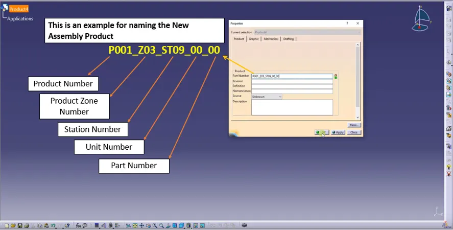
An example is provided for naming the new product.
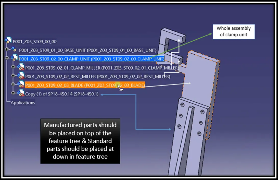
An example is provided for naming the new product with parts.
Structuring a design tree refers to the systematic practice of naming assemblies and parts according to specific standards. This process is crucial for ensuring clarity and organization in design documents. Here's how structuring a design tree reduces errors during the design process:
-
Clear Identification: By following naming standards, each part or assembly is uniquely identified, making it easy to determine which project, tool, or unit it belongs to. This clarity helps designers and team members avoid confusion and ensures that everyone is on the same page.
-
Error Prevention: Properly named and structured design trees help prevent errors at various stages of the design process, including design study, manufacturing, assembly, and inspection. When components are clearly labeled and organized, it's less likely that mistakes will occur due to misinterpretation or oversight.
-
Consistency: Standardized naming conventions promote consistency throughout the design, reducing the chances of inconsistencies or discrepancies that could lead to errors.
-
Efficient Communication: Structured design trees facilitate effective communication among team members. When everyone uses the same naming conventions, it becomes easier to discuss and reference specific parts or assemblies, minimizing the risk of misunderstandings or errors.
-
Quantity Control: The structured design tree can also provide valuable information about the quantity of items used in an assembly, helping to ensure that the correct number of components is included and reducing the risk of assembly errors due to missing or excess parts.
........................................................................
Q11. What are Units? Mention 5 types of units.
ANS:
"Units" in a Body-in-White (BIW) fixture production process refer to specific zones or components across the assembly line that carry out particular tasks or processes throughout the construction of the vehicle body. These devices are set up and built to efficiently complete specified duties.
Here are five types of units commonly found in a BIW fixture assembly line:
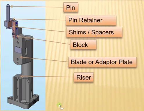
Fixed Pin Unit: Fixed Pin unit is a unit designed to locate the car panel using pins and below are the different parts of a fixed pin unit in general.
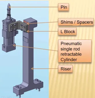
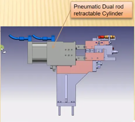
Retractable Pin Unit: A retractable pin unit is a unit designed to locate the car panel using pins, but the entire pin package parts will mounted on the retractable pneumatic cylinder.
And below are the different parts of a retractable pin unit in general.
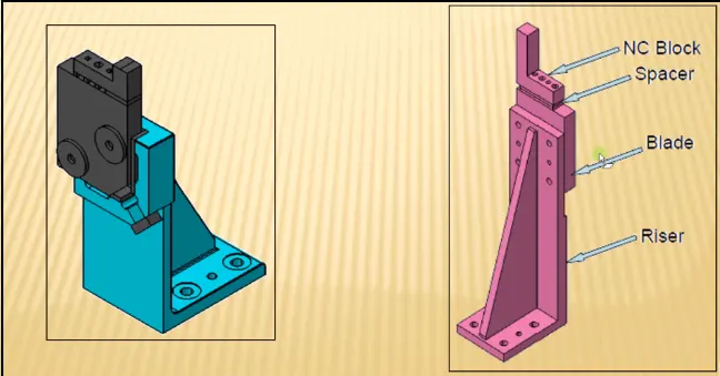
Rest Unit: A rest unit is a unit designed to rest / support the car panel using NC blocks / Mylar / Rest.
And below are the different parts of a rest unit in general.
Clam Unit : A clamp unit is a unit designed to clamp / hold the car panel with NC blocks / Mylar / Rest by using a pneumatic clamp cylinder. And below are the different parts of a clamp unit in general.
Sensor Unit: A sensor unit is a unit designed to sense the car panel by using Electrical sensors. This signals from the sensors will be fed to the PLC and so the next proc:ess will executed by this signal.
Fundamentals of Sensor unit design:
- Every single loose panel which are being welded in a tool should be sensed.
- Each panel should be sensed by 1 to 2 sensors depend on the size of panel, Preferred to be in diagonal opposite ends of panel.
- Every sensor should be mounted in a 3 direction adjustable way in general.
Some major sensor manufactures are IFM, Pepperl-fuchs, SICK, OMRON etc
Types of sensors used in general :
- Proximity sensors
- LASER sensors
- Photo electric sensors
some of the sensor images are provided below

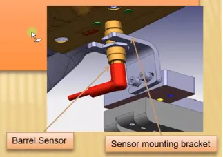
...........................................................................
Q12. Describe Fixed Pin units & their purpose?
ANS:
A Fixed Pin Unit in the context of automotive Body-in-White (BIW) fixture assembly is a specialized workstation or fixture designed for the precise positioning and locating of car body panels or components using pins. These units are a critical part of the assembly line, ensuring that the panels are accurately aligned and held securely in place during welding, assembly, or other manufacturing processes.
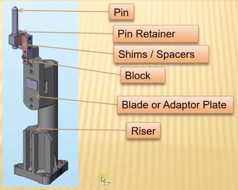
An example of a pin unit is presented above
Here's a more detailed explanation of a Fixed Pin Unit:
1. Pin-Based Locating System: A Fixed Pin Unit is equipped with a system of pins that are strategically positioned and designed to match the contours and mounting points of specific car body panels. These pins serve as reference points to locate and secure the panels in the correct position.
2. Precision Alignment: The pins are precisely placed to ensure that the car body panels are aligned with extremely high accuracy. This alignment is crucial for achieving the desired fit and finish of the vehicle, as well as ensuring that all panels meet the specified tolerances.
3. Panel Stability: The Fixed Pin Unit's primary function is to hold the car body panels securely in place, preventing any movement or deviation during subsequent manufacturing processes, such as welding or assembly. This stability is essential to avoid errors and defects in the final product.
4. Consistency and Repeatability: Using a Fixed Pin Unit guarantees consistency and repeatability in the assembly process. Once the pins are set for a particular car model, they can be used repeatedly to assemble multiple vehicles with identical panel alignment.
5. Reduced Manual Labor: By automating the process of panel alignment and locating using pins, the Fixed Pin Unit reduces the need for extensive manual labor and measurement, thus improving efficiency and reducing the potential for human error.
6. Customization: Fixed Pin Units are often designed to accommodate various car models and body types. They can be customized to fit the specific dimensions and shapes of different panels, allowing for flexibility in production.
7. Quality Assurance: The use of Fixed Pin Units contributes to the overall quality assurance process by ensuring that car body panels are correctly positioned and that tolerances are met. This helps prevent issues such as misalignment, gaps, or welding defects.
............................................................................
Q13. What are the different parts of a fixed unit?
ANS:
Fixed Pin unit is a unit designed to locate the car panel using pins.
And below are the different parts of a fixed pin unit in general.
- Pin :
- It serves as the panel's location reference. The locating pins are typically used to precisely locate a body part so that welding may be done on it.
- A collection of properly placed locating pins is what constrains the body part, therefore entire constraint by locating pin should be totally limited at all times to prevent any movement.
- There are many locating pin designs that can be used in a design. A stepped pin with a tiny or large head is one of the most popular pins
An image of different pins are shown above
- Pin Retainer:
- The locating pins are held firmly in place by a pin retainer.
- The pin retainer serves as both a rest and a means of holding the pin in place. A pin-fitting counter hole that has been drilled.
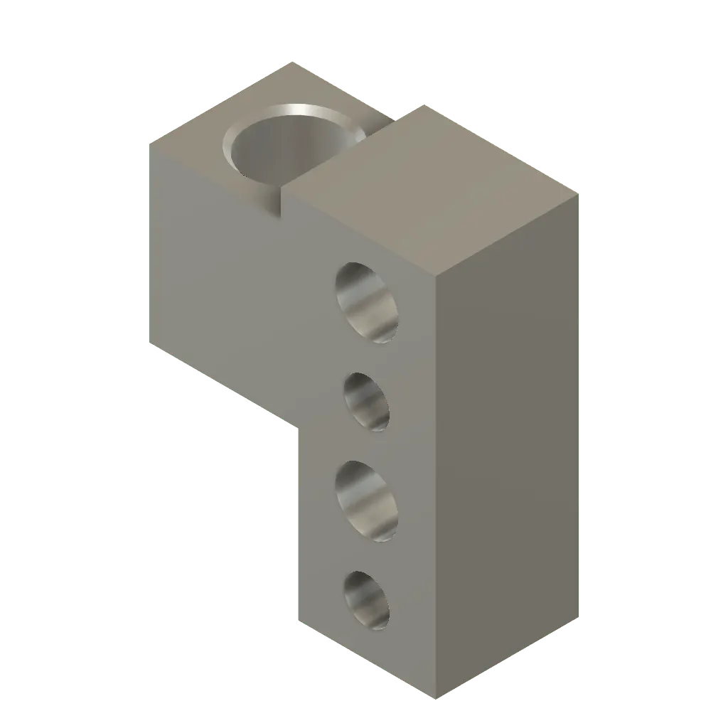
An image of Pin Retainer is shown above
- Shims / Spacers: Shims are small, flat pieces or strips of material that are fitted between components to change their tolerances, spacing, or alignment. Shims are used for a variety of tasks including alignment in a variety of sectors, such as automotive production and BIW (Body-in-White) fixture assembly units. Shims may be constructed from a range of materials, including metal (such as steel or aluminum), plastic, rubber, or composites. They are available in a range of sizes and thicknesses to satisfy various adjustment requirements. Shims are a useful tool in manufacturing and assembly operations because they assist maintain quality and efficiency while achieving precise and dependable outcomes.
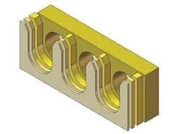
An image of shims is shown above - Block: Blocks are normally solid, frequently cuboid- or rectangular-shaped items made of a variety of materials, including metal, plastic, or composite materials. In industrial and manufacturing environments, blocks are used for a variety of tasks, including the installation of Body-in-White (BIW) fixture modules. Blocks can come in a variety of sizes, shapes, and designs depending on the particular specifications of the production process. When it comes to guaranteeing accuracy, stability, and efficiency in a variety of industrial and assembly applications, blocks are incredibly useful tools.
An image of different Blocks are shown above - Blade or Adaptor Plate:
- Blade are the plates which are attached to raiser.
- Blade is also attached or mounted with cylinders, arms etc.
An image of Blade is provided above
- Riser: Riser is a manufacturing part used to raise / height the assemblies of fixture. One end of the raiser will be attached to the blade.
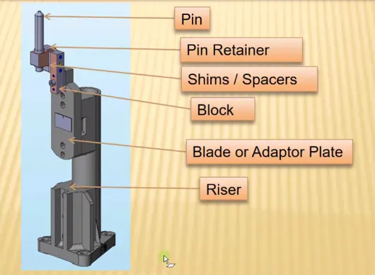
An image of Blade is provided above
..........................................................................
Q14. What is the purpose of making a Rest unit & describe its parts?
ANS:
Rest Unit: A rest unit is a unit designed to rest / support the car panel using NC / Mylar / Rest.
And below are the different parts of a rest unit in general.
A "rest unit" is a specialized workstation or fixture designed to support and keep car body panels or components securely in place throughout various production processes, particularly in Body-in-White (BIW) fixture assembly. A rest unit's main objective is to make sure that the car panels are properly supported and positioned in order to avoid distortion, damage, or misalignment during welding, assembly, or inspection procedures. For panel support, rest units can use a variety of materials, including NC (Nylon Coated), Mylar, or other appropriate materials. I'll go into more detail about the many elements and parts that are frequently present in a rest unit below:
-
Support Surface: A rest unit features a specialized support surface designed to hold and align car body panels securely during manufacturing processes. This surface is contoured to match the panel's shape and is typically coated with materials like NC (Nylon Coated) or Mylar to prevent surface damage.
-
Rest Pins: Rest pins are integrated into the unit to engage specific features on the car panel, ensuring precise alignment and positioning. They can be adjusted to accommodate different panel sizes and configurations.
-
Height and Adjustment Mechanisms: Rest units are equipped with height and adjustment mechanisms that enable fine-tuning of the support surface and rest pins. These adjustments are crucial for accommodating variations in panel thickness and contour.
-
Clamping and Locking: Some rest units include clamping mechanisms, often pneumatic or hydraulic, to securely hold the car panel in place during manufacturing. Locking mechanisms are also used to prevent unintended movement once adjustments are made.
-
Load Distribution: Rest units are designed to distribute the load evenly across the panel, preventing localized stress and minimizing the risk of deformation or damage. This ensures that panels are properly supported and protected during the manufacturing process, contributing to quality and accuracy.
In conclusion, a rest unit is an essential part in assembling BIW fixtures in the automotive industry. It contributes to the precision, quality, and efficiency of welding, assembly, and inspection activities by providing critical support and accurate positioning for automobile body panels. Rest units are adaptable tools that can accommodate various panel kinds and sizes while guaranteeing the protection and integrity of the panels thanks to the presence of materials like NC or Mylar coatings and the insertion of adjustment and clamping mechanisms.
.........................................................................
Q15. What are the basic fundamentals to design a Sensor unit?
ANS:
A "Sensor Unit" is an individual unit or component that includes a number of sensors to track and gather data during the production process. In order to measure important parameters and properties of the components being assembled or welded, these sensors are placed strategically within the fixture. A sensor unit in a BIW fixture is primarily used to guarantee the precision, excellence, and consistency of the assembly or welding operations. During the assembling or welding process, a sensor unit in a BIW fixture uses a variety of sensors to monitor and control important factors. Sensor units support the maintenance of high levels of precision, quality, and effectiveness in the production of vehicle body-in-white structures by continuously gathering and evaluating data.
FUNDAMENTALS TO DESIGN A SENSOR UNIT
- Every single loose panel which are being welded in a tool should be sensed.
- Each panel should be sensed by 1 or 2 sensors depend on the size of the panel, preferred to be in diagonal opposite ends of panel.
- Every sensor should be mounted in a 3 direction adjustable way in general.
- We should try to minimize the size of sensor as much as possible.
- Some major sensor manufacturers are IFM, Pepperl – fuchs, sick, OMRON, etc.
TYPES OF SENSORS USED IN GENERAL
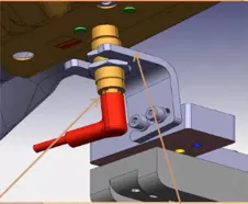
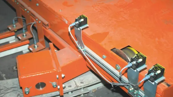
PROXIMITY SENSOR: An electromagnetic field or a beam of electromagnetic radiation is frequently emitted by a proximity sensor, which then monitors the field or return signal for changes. The target of the proximity sensor is often used terminology.
LASER SENSOR
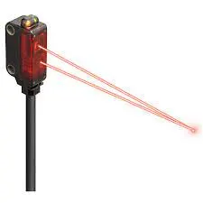
- These laser distance sensors gauge a distance to a target item using a focused, coherent light. Targets in applications for manufacturing automation are frequently products or machine parts.
- They can identify any solid object and provide a signal proportional to the distance measured, regardless of the item's substance, color, or brightness.
- Laser distance sensors' high resolution output is used to provide position or displacement information, typically as an input to an industrial controller like a Programable Logical Control (PLC).
- The output signal frequently features high accuracy and temperature adjustment to improve stability.
- There are various kinds of laser distance sensors, including retroreflective, diffuse, and background suppression.
- These sensors provide precise distance measurements using CMOS (Complementary metal–oxide–semiconductor) or transit time methods.
PHOTOELECTRIC SENSOR
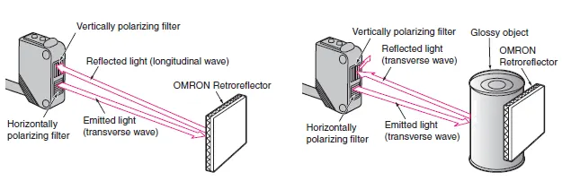
- A photoelectric sensor, often known as a photo eye, is a piece of equipment that uses an infrared light transmitter and a photoelectric receiver to determine the proximity, absence, or presence of an object.
- They are primarily employed in manufacturing for industry.
- There are three different practical types: proximity sensing, retro-reflective, and opposing.
........................................................................
Q16. What is a Rough locator unit & what are the basic fundamentals to consider while designing it?
ANS:
In the Body-in-White (BIW) fixture assembly process, a "rough locator unit" assists workers in roughly locating car body panels into defined fixture points like pins or reference markers. The subsequent assembly or welding operations depend heavily on this initial alignment. A rough locator unit can be either a generic, aftermarket component appropriate for many different automobile models or a specially manufactured solution made to fit particular panel shapes and sizes.
A Rough locator is a part designed to guide the operator, to locate the car panel on to the pins accordingly. A rough locator can be of standard part or make part.
Fundamentals of Rough locator design:
- Rough locators should be placed at the edges of the car panel, which it has to guide.
- Rough locators has to be placed in the same angle of the car part edge with a minimum distance of 2-5mm from the edge of the car part.
- Rough locators should guide the panel in pin arresting direction.(ln general)
- Rough locators should start guiding the panel before 10 to 15 mm to the start of the pin engagement.
- Rough locators should be designed with entry angle for car part entry.
- Rough locators should be designed with two slots to mount for easy adjustments. (In general)
- The slots should be in the direction of car part guiding.
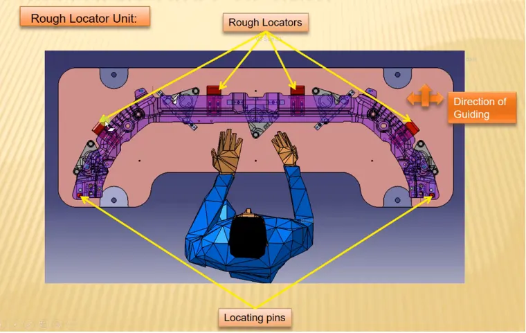
An image of rough locators using in BIW fixture
.......................................................................
Q17. What is a Base unit and describe it's parts?
ANS:
Base Unit: A base unit is the unit designed to mount all the other units(Clamp unit, Pin unit, rest unit etc.,) of the tool, also other parts necessary for a tool like pneumatic valve box, trunking cable path will also be mounted on to a base unit. And below are the some parts of abase unit in general.
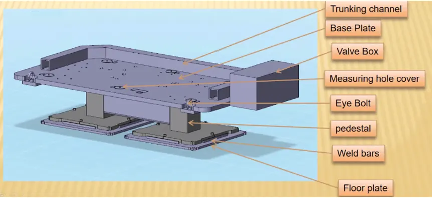
-
Base Unit: The base unit serves as the foundational structure of the tool or fixture. It is designed to securely mount and support all other units, including clamp units, pin units, rest units, and additional components.
-
Trunking Channel: The trunking channel is a structural component that provides a pathway for cables and wiring within the tool. It helps organize and protect electrical and pneumatic connections, ensuring a tidy and efficient setup.
-
Base Plate: The base plate is a large, flat component that forms the bottom surface of the tool. It provides stability and a secure foundation for the entire tool, preventing it from shifting or vibrating during operation.
-
Valve Box: The valve box houses pneumatic valves and controls that are integral to the operation of the tool. It allows for the regulation of air pressure and the activation of various pneumatic components within the tool.
-
Measuring Hole Cover: Measuring hole covers are protective covers or caps used to seal openings or holes in the tool's structure. These covers prevent debris, dust, or contaminants from entering and affecting the tool's precision.
-
Eye Bolt: Eye bolts are attachment points on the tool used for lifting, securing, or attaching components. They are typically fitted with a loop or eyelet for connecting lifting equipment or other hardware.
-
Pedestal: Pedestals are support structures or columns that elevate specific components or units within the tool. They are used to achieve specific heights or alignments as needed for the manufacturing process.
-
Weld Bars: Weld bars are fixtures or clamping components used for securing workpieces during welding processes. They ensure that components are held in the correct positions and orientations for welding operations.
-
Floor Plate: The floor plate is a component that forms the lower surface of the tool. It provides additional stability and structural support to the tool, especially when placed on a factory floor.
....................................................................
Q18. What is a Dump Unit and what are its functions?
ANS:
Mechanical systems known as dump units are used in a variety of sectors to efficiently handle and transfer commodities. This article gives a concise introduction of dump units, describing their many functions and outlining their goal.
Dump units, also known as dump mechanisms, are hydraulically powered mechanical apparatuses. By raising and lowering cargo beds or containers, they primarily serve to permit controlled material discharge and enable accurate loading, unloading, and dumping.
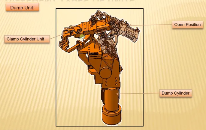
Dump units have important functions in the manufacturing process of BIW:
- Material Handling: Ensure effective assembly by optimizing the transfer of bulk materials throughout the BIW production process. This will reduce manual labor requirements and improve material distribution.
- Waste Management: Improve waste management by making it easier to dispose of materials in designated areas, which will improve the manufacturing facility's cleanliness and waste management effectiveness.
- Component Transfer: Make it possible for the controlled and effective transfer of BIW parts and components, making sure they are placed correctly for welding, assembly, or other processing.
- Improving logistics and material flow inside the BIW manufacturing environment can help to support just-in-time manufacturing procedures and minimize production delays.
.....................................................................
Q19. What are slide units? Mention where slide units are commonly used?
ANS:
Slide units, also known as linear slides or linear motion systems, are critical mechanical components extensively employed in a wide array of industrial applications. This report provides an overview of slide units, elucidating their characteristics, primary functions, and their significance within the context of Body-in-White (BIW) assembly lines in the automotive industry.
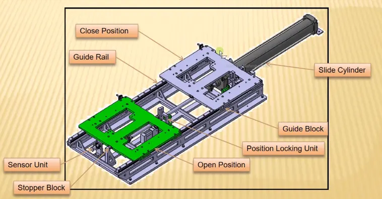
Slide units are mechanical devices designed to facilitate controlled linear motion or translation of objects along a fixed path. They typically incorporate sliding components, such as bearings or guides, to ensure precise and smooth movement.
Common Uses of Slide Units:
- Manufacturing and Automation: In manufacturing and automation operations, slide units are frequently used to enable the precise positioning and movement of machinery parts, conveyor systems, and robotic arms.
- Machine Tools: Slide units are essential to the operation of machines like lathes, milling machines, and CNC equipment in the machine tool industry, maintaining the accuracy of shaping and cutting operations.
- Packaging and Material Handling: Slide units are essential to the packaging industry because they allow for controlled movement on conveyor systems, product assembly lines, and packaging machinery.
- Medical and Laboratory Equipment: Slide units are essential components of laboratory and medical equipment, helping with activities like moving the microscope stage and handling samples for precise medical treatments.
- Aerospace and Automotive: Slide units aid in the precise movement of aircraft parts in aerospace applications, and they support testing and assembly line equipment in the automobile sector.
.................................................................