Wiring harness routing & packaging Rules Week 3 Challenge
Report on Wiring harness routing & packaging Rules
Q1. Download the following cad data & define it as Electrical support using the Electrical Part Design Workbench. Define all the necessary properties.
Here the CAD Data provided is P Clamp which is shown in the above Image and the Link to P Clamp
Introduction:
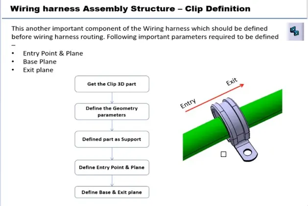
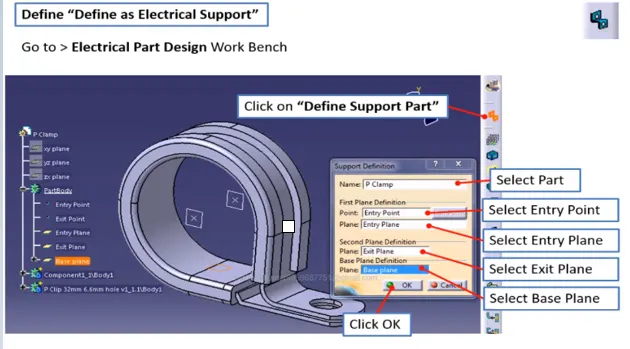
Steps that are to follow to define the P Clamp as Electrical Support using Electrical Part Design Workbench in CATIA V5.
- Open the 3D CAD Data in either a .igs file or a .stp file in CATIA V5 Software.
- Now specify the Geometrical parameters for the P Clamp like points and planes which are needed to define it as Electrical support.
- We have to determine the geometrical parameters in Part Workbench as it is not possible to create points and planes in Electrical Part Workbench.
- After defining the Points & planes switch to Electrical Part Workbench and Click on "Define Support Part."
- On selecting the Part body the Support Part gets activated and here we can provide the entry point and also we can give entry, exit & base planes.
- Do the same in other directions as the bundle can pass in bi-directional. Check the precaution if you can't be able to select the point for the second direction.
- If you face any issue with point definition or point selection, Right-click on the point definition window and use the reset option.
- Make sure to save the file in the appropriate folder once the steps mentioned above have been finished.
Images of P Clamp with feature tree
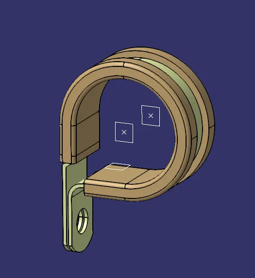
Image of P Clamp
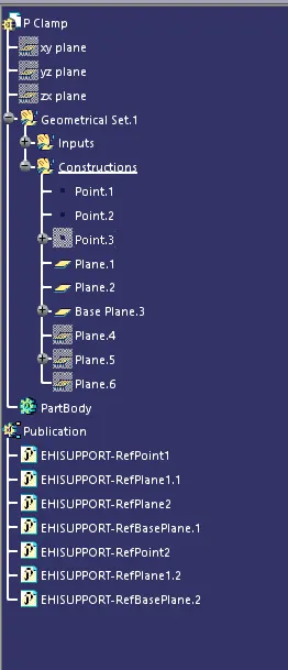
Feature Tree Image of the P Clamp
.........................................
Q2. Download the following Back shell cad data & define it as an Electrical back shell using Electrical Part Design Workbench. Define all the necessary properties.
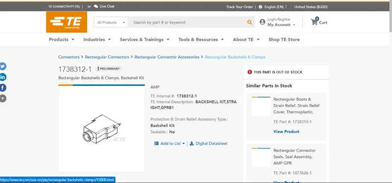
https://www.te.com/usa-en/product-1738312-1.html
Here the CAD Data provided is the Back Shell which is shown in the above Image and the Link of the back shell.
Introduction:
- Backshells are plastic molded parts used at the wire entry side of connectors either for protection or to improve the aesthetics/appearance of the harness.
- These are not mandatory parts of the Wiring harness. Are always optional and driven by Cost.
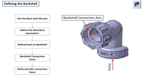
Steps that are to follow to define the Tyco 1738312-1 Back Shell as an Electrical Back Shell using Electrical Part Design Workbench in CATIA V5.
- Open the 3D CAD Data in either a .igs file or a .stp file in CATIA V5 Software.
- Now specify the Geometrical parameters for the Back Shell like points and Axis Systems which are needed to define it as an Electrical Back Shell.
- We have to determine the geometrical parameters in Part Workbench as it is not possible to create points and Axis Systems in Electrical Part Workbench.
- The methodology and logic to define the Point & Axis system are the same as the Connector Connection system.
- Ensure that the defined axis & Orientation should be identical to the mating part.
- After defining the Points & Axis systems switch to Electrical Part Workbench and Click on Define Back Shell.
- Now click on Part Body and click on the "Define Back Shell" option and click OK.
- Then click on the "Define Back Shell Connection Point" option and specify the parameters as "Backshell Connection Point" for Representation, "Face" that will get into contact after mating with the connector as Contact.
- For coincidence select Y-Axis and for Orientation Select X-Axis.
- And also make sure to specify Bundle Connection parameters.
- Then save the file in the appropriate folder once the steps mentioned above have been finished.
Images of Tyco 1738312-1 Back Shell with feature tree
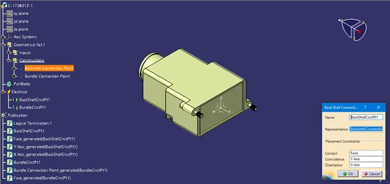
Image of Defining Back Shell Connection Parameters with Feature Tree.
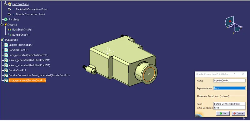
Image of Defining Bundle Connection Parameters with Feature Tree.
.........................................
Q3. Create the Following Corrugated tubes & Add them to Catalogue under the “Slit COT” family.
|
Name |
ID (mm) |
OD (mm) |
Thickness (mm) |
|
15mm COT |
12 |
15 |
1.5 |
|
20mm COT |
17 |
20 |
1.5 |
|
35mm COT |
32 |
35 |
1.5 |
|
10mm COT |
7 |
10 |
1.5 |
|
5mm COT |
3 |
5 |
1 |
Here we need to create Corrugated tubes with different diameters and store them in a Catalogue.
Introduction:
- Corrugated tubes, Convolutes, Sleeves & many other types of coverings are used to protect the wiring harness.
- Graphical representations of coverings are applied on bundles.
Steps that are to follow to Create the Corrugated tubes which are mentioned below & Add them to Catalogue under the “Slit COT” family.
- First, open CATIA V5 Software and Click on New to Create a "CatalogDocument" which is under the List of types in "New".
- Now under the Chapter tools bar and select "Add family."
- Then rename it into "Slit COT" & select the type as "Conduit" and Save the file.
- After that Create COT Tubes or Corrugated tubes by following the shown below three steps we can create COT tubes with different Inner Diameters.
- Create a New Part File, go to "Electrical Part Design" Workbench & Click on "Define Protection Part" under the Electrical Device Definition toolbar.
- Now select PartBody from the feature tree and give the Inner Diameter & Thickness as inputs.
- Make sure the Bend Radius is not less than 1.5 times of inner diameter and also Outer Diameter is nothing but the sum of the Inner Diameter and Thickness.
- Then save the Part file in the required folder and now click on the "Store Device" Icon which is under the "Electrical Device Storage" toolbar.
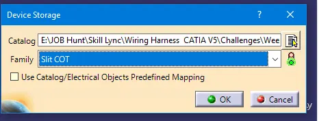
- Now browse the catalog file that we have created before as "Slit COT Catalog" and select the family as "Slit COT."
- At last, click "OK" and do the same for all 5 different COT Tubes with different Diameters.
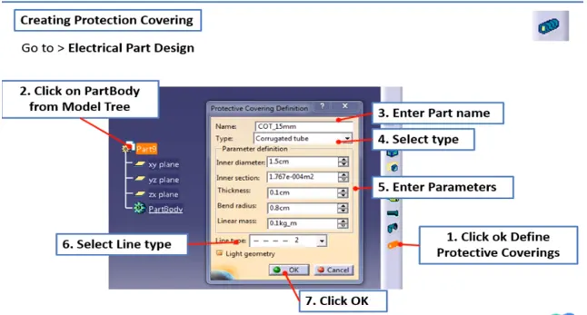
Images of COT Tubes with the Catalog that stored devices
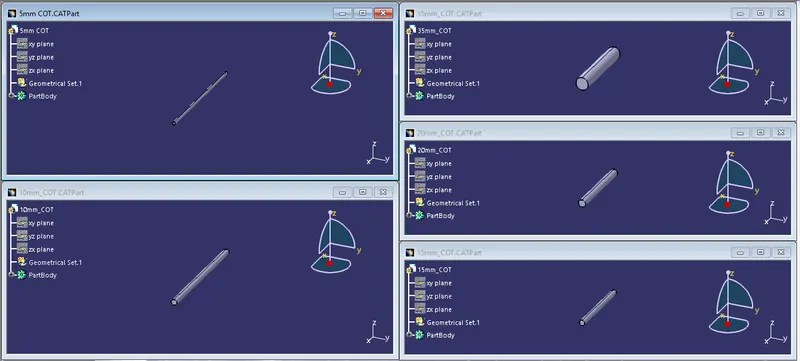
Images of COT Tubes that are Created.
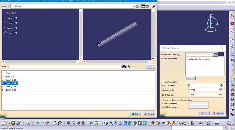
The catalog that COT Tubs are Stored.
.........................................
NOTE_1: .igs files are imported to define the components so that all the components have surface bodies only not solid bodies. If .stp files were considered it would be solid files.
NOTE_2: All the files have been uploaded as a Single ZIP file and attached.