Fender Design - Wheel Arch Challenge
Wheel Arch - Calculations
Aim:
Calculate the Wheel Arch gap at the required points and check whether the car passes the European standard.
Objective:
- Find out about the various wheel arch gap parameters.
- For the European standard, draw the lines at the necessary angles and locations.
- Measure the distance at each angle and indicate whether the model is correct or incorrect.
Fender:
The fender frames the wheel bottom on an automobile, motorbike, or other types of vehicle. Its main objective is to stop the revolving tires from launching debris including sand, dirt, gravel, liquids, and other road sprays into the air. Since fenders are usually inflexible, contact with the road might harm them.
The primary function of a car's fenders is to protect the body from damage while also shielding the underbody from the flying debris that might result from a car's rotating wheels moving at high speeds when it is moving.
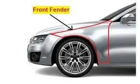
Wheel Arch:
The wheel arch is the semicircular part positioned above the wheel of a vehicle. The most important body change was that the front wheel arch was cut higher into the fender. The shaped part of the bodywork of a car or other vehicle that allows the wheel to be accessed, and in the case of front wheels, enables them to be steered.
Right over the wheel, it is a curved portion of the fender. The pedestrian and car cabin are both protected by the wheel arch from dirt, water, rocks, and road spray. The wheel arch design must adhere to the country's specific wheel arch requirements in order to be considered appropriate there. Design characteristics are taken into account in order to prevent design modifications of the same vehicle to comply with various requirements.
Fender Wheel Arch Regulations :
Japanese Regulations :
- Measure the clearance "L" for the tire, hub, cap, and fender inside region K, then develop a clearance check chart to verify.
- In every position, L should be greater than 5mm.
- Wheel guards are necessary: At lines 30 degrees ahead and 50 degrees back from the central vertical axis of the wheel, the value of "a" should be greater than 5mm.
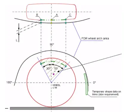
Norms in Europe:
- In order to validate, the clearance "L" should be measured at the sections SA-SA, SB-SB, SC-SC, SD-SD, and SE-SE.
- To comply with European Regulations, the value of L at each of the five parts must be more than 10mm.
- Wheel guard requirement: At lines 30 degrees in front of and 50 degrees behind the center vertical axis of the wheel, the value of "a" shall be more than 5mm.
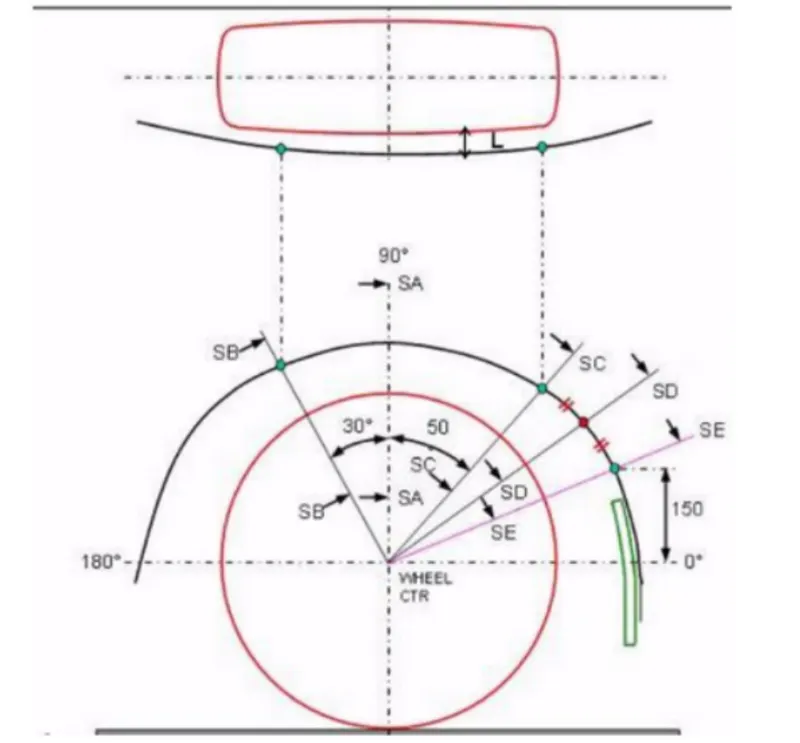
US Regulations:
- From -100 degrees to 100 degrees, clearance "L" must be checked at every angle, and a clearance check chart must be created to prove this.
- To comply with the standards, L's value must be greater than 5mm.
- Wheel guard requirement: At lines 30 degrees in front of and 50 degrees behind the center vertical axis of the wheel, the value of "a" shall be more than 5mm.
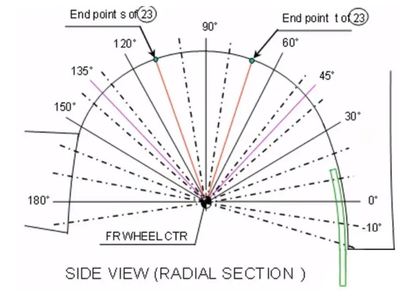
Calculation according to European Regulations
We must draw a diagram on the wheel's outermost face in order to calculate the clearance between the wheel arch and the wheel. The steps are as follows.
We must open the part file from the supplied source in NX CAD, and the part file contains the wheel and fender. Therefore, we must now check for the standard of European regulations. Now, as shown in the picture, we must establish the Datum plane at the wheel's outermost face.
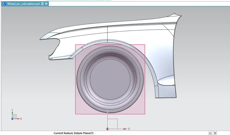
Then, using the Rapid dimension as depicted in the image, we sketch the lines in that plane and then provide the necessary angle using the reference of the European standard drawing.
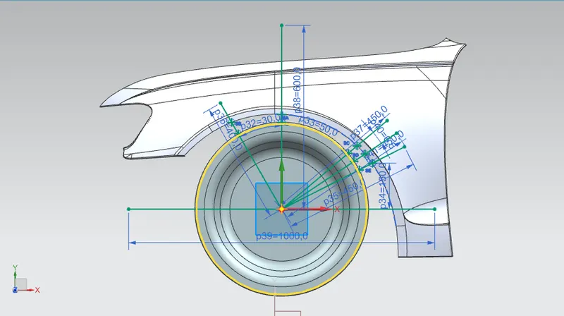
The dimensions are established in accordance with the European standard as indicated in the picture, and using the text, give the lines their correct names.
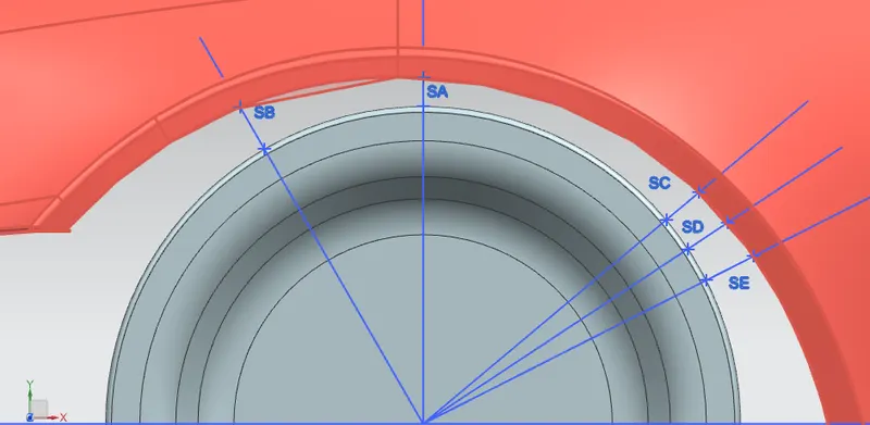
Then, as indicated in the picture, we add some points to the face and an angled line to measure the distance between the outermost wheel and the outermost wheel arch.
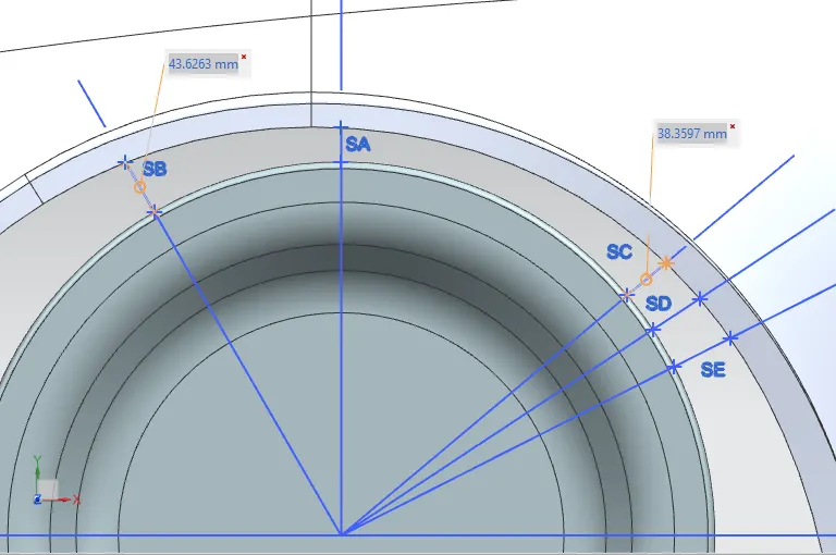
Now, using the NX Cad's analysis tab, click simple distance to measure the necessary distances in accordance with the European standard, as indicated in the figure. As shown in the figure, the clearance distance from the SB line is 43.6263mm, while the clearance distance from the 50-degree SC line is 38.3597mm.
standards :
- At lines 30 degrees ahead and 50 degrees, "a" should be more than 5mm.
- L must be bigger than 10mm.
The measurements for clearance are given below
for "a" values
SB = 43.6263mm
SC = 38.3597mm
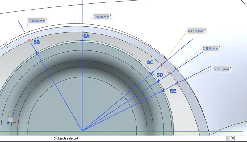
for "L" values
SB-SB = 10.0 mm
SA-SA = 9.94 mm
SC-SC = 0.11 mm
SD-SD = 2.88 mm
SE-SE = 5.99 mm
Tabular form for design considerations
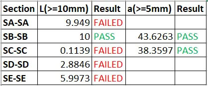
Conclusion:
Since this design does not reach the required minimum space of 10 mm between the fender arch wheel and the outermost wheel, the fender fails to fulfill the requirements of the European Regulation standard. This conclusion can be drawn from the results presented above.