Wiring harness design in CATIA V5 - 3D modeling Week 5 & 6 Challenge
Report for the following Wiring Harness Assembly
Routing the following harness layout in Electrical workbench by making assumption for harness bundle diameters by using the connectors provided. After completion of routing,
- Checking the bundle Continuity and Adding a snap of result in report.
- Adding annotations to all connectors by make an assumptions for annotations like connect 1 , 2 etc
- Checking for the bundle warning and Adding a snap of it.
- Generating a CAT.part of harness assembly and converting it in .igs format and .stp format.
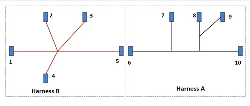
Note: Required Files have been provided.
Steps for creation of Wiring Harness Product Assembly and checking Bundle Segment Continuty
- Download the files that are provided and define them as electrical parts.
- Create a Wiring Harness A and Wiring Harness B as shown in the above picture.
- Now create a Product File and insert both the Wiring Harnesses into it and Connect 5th connector from Harness B to 6th connector from Harness A.
- Now check the bundle Continuity by using Search option from Edit menu or press Ctrl+F.
- Then go to Advanced tab and select workbench as Electrical, Type as Bundle Segment and Attribute as fully connected.
- When you select attribute as fully connected, Attribute Criterion window will be opened.
- Select second option as FALSE and click OK.
- Then in Composed query it will show as "Electrical.'Bundle Segment'.'fully connected'=FALSE"
- Now click on Search
 symbol. If there is any discontinuty it will show under.
 - Some of the pictures a have added below for better understanding.
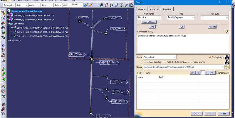
- If we click on TRUE option it will show all connected Bundle Segment.
Steps for creating annotations to all connectors
- Switch to the assembly design workbench and make sure the geometrical bundle is active.
- Select the front view/ annotation plane
 icon and select the plane you wish to use for the annotation.
 - Select the flag note with lader
 icon and Click on the part you wish to add the annotation for.
 - Input the information that you want to provide in the name definition and click OK.
- Some of the pictures a have added below for better understanding.
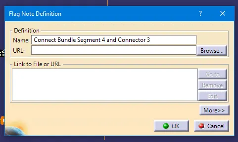
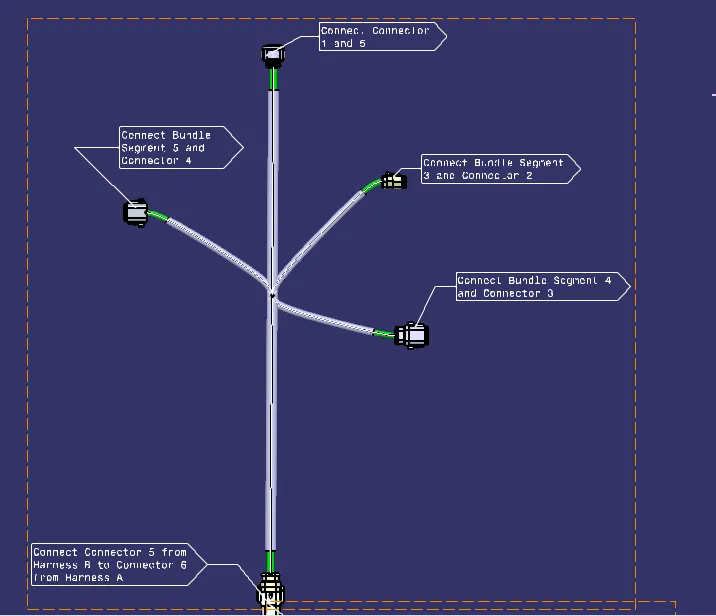
Image of Wiring Harness B with annotations. - To change the font size, right-click on the the annotation and go to Font Tab and select the parameters as you like.
- Do the same for all connectors in Harness A and Harness B.
Checking for the bundle warning and Adding a snap of it.
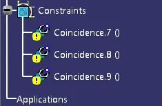
To avoid this warnings once update the product file by clicking update all icon or press Ctrl+U.
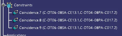
Image after updation
Steps for Generating a CAT.part of harness assembly and converting it in .igs format and .stp format.
- While you are in Assembly Design Workbench go to Tools menu and Click on Generate CATPart from Product.
- And provide name for the CATPart that we are creating and click OK.
- After Generating of the CATPart file save the File in required folder.
- To create .igs file or .stp file click on Save As and select save as type as "igs" and click Save
- Follow the same procedure for .stp file.
Images of Wiring Harness Product Assembly
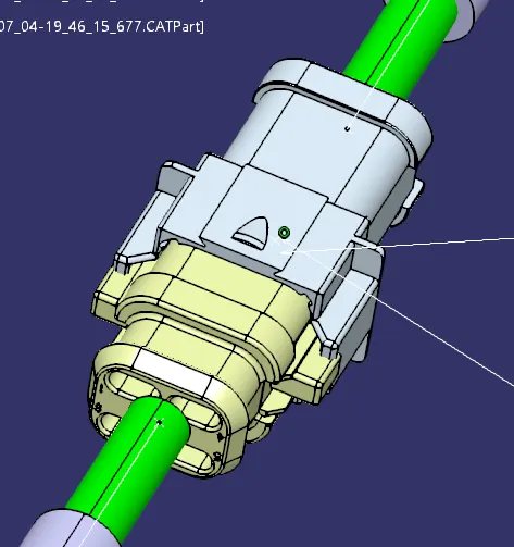
Image of Product Assembly
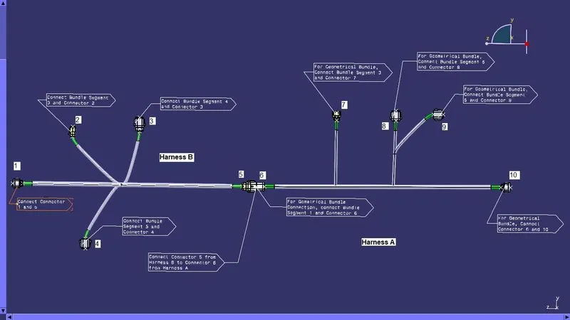
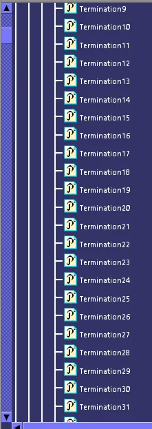
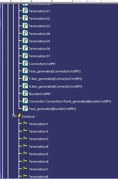
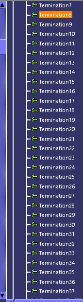
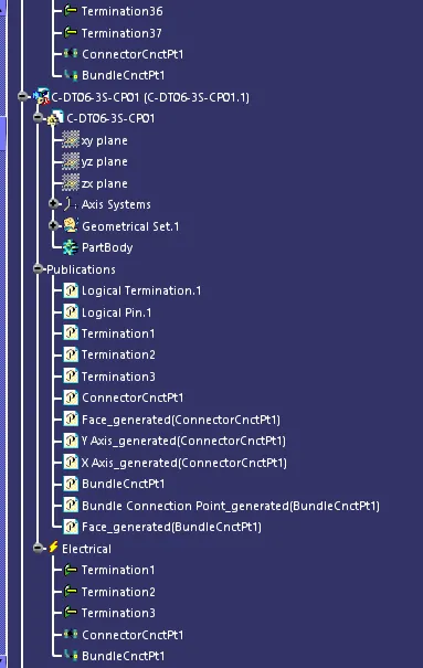
Feature tree Images
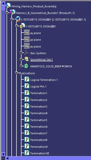
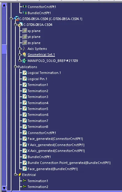
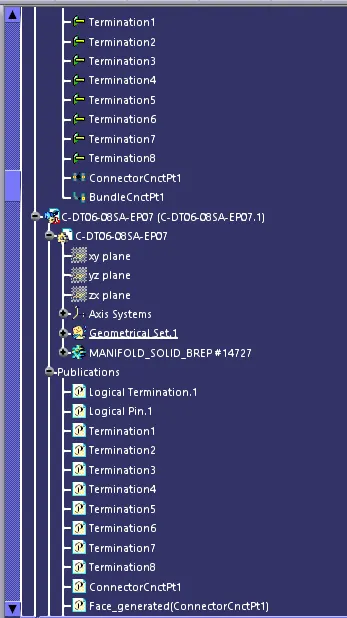
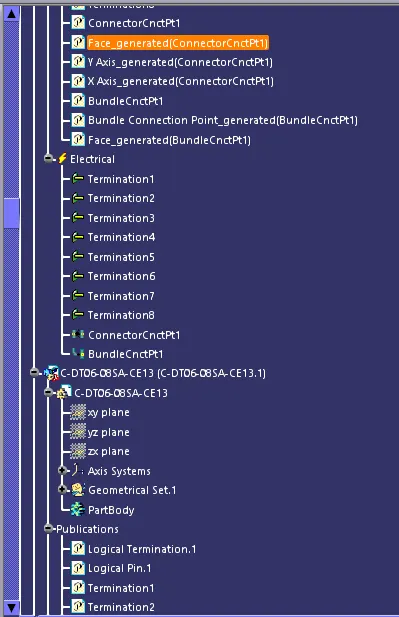
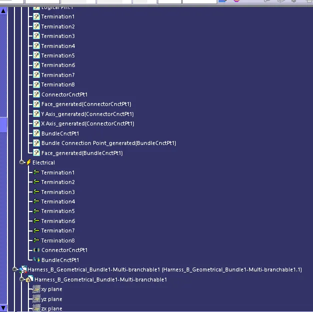
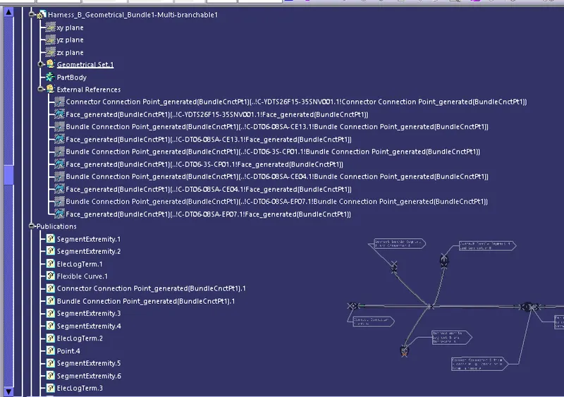
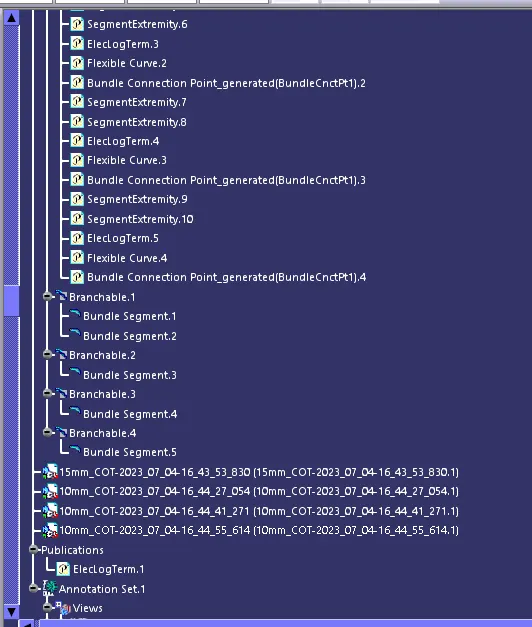
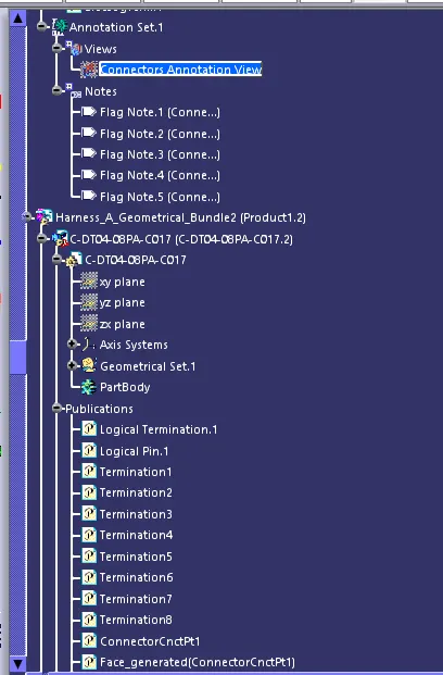
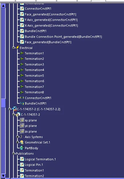
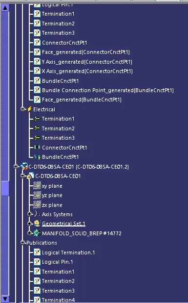
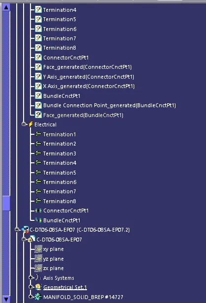
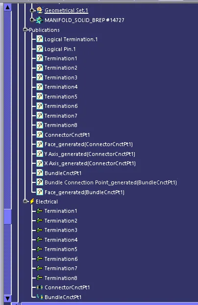
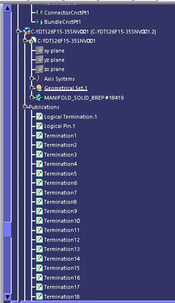
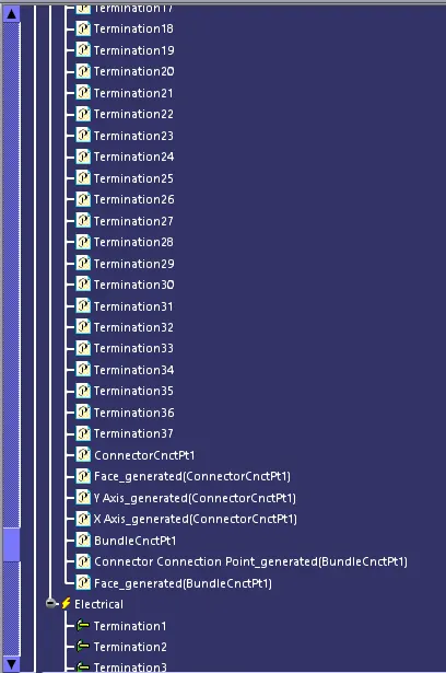
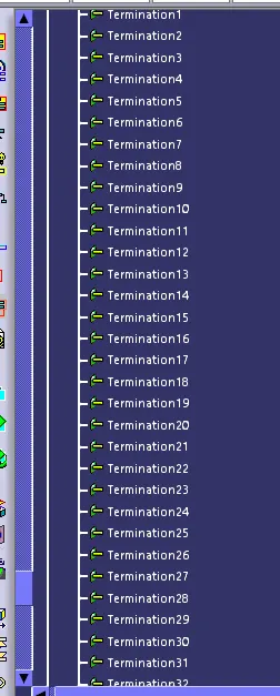
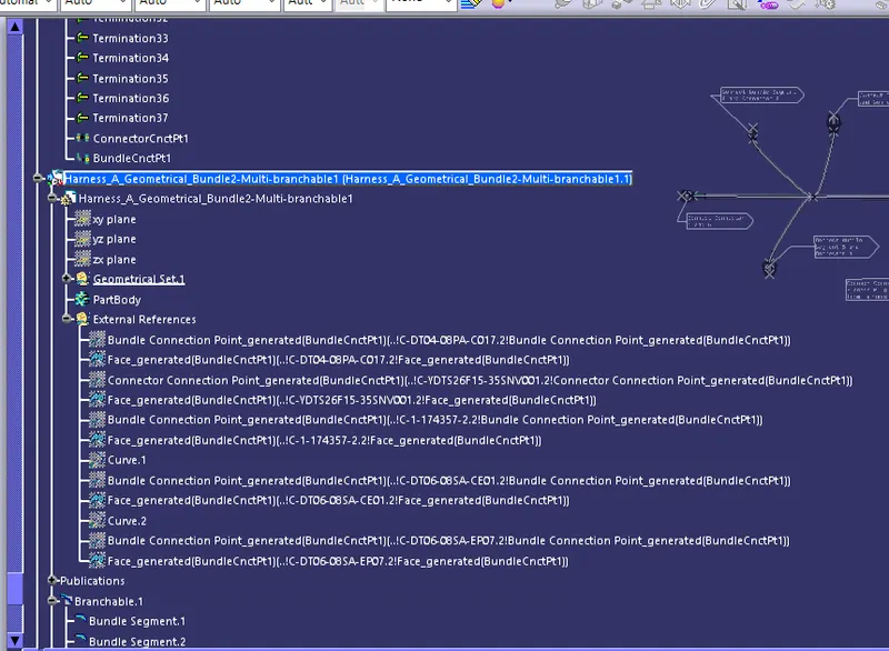
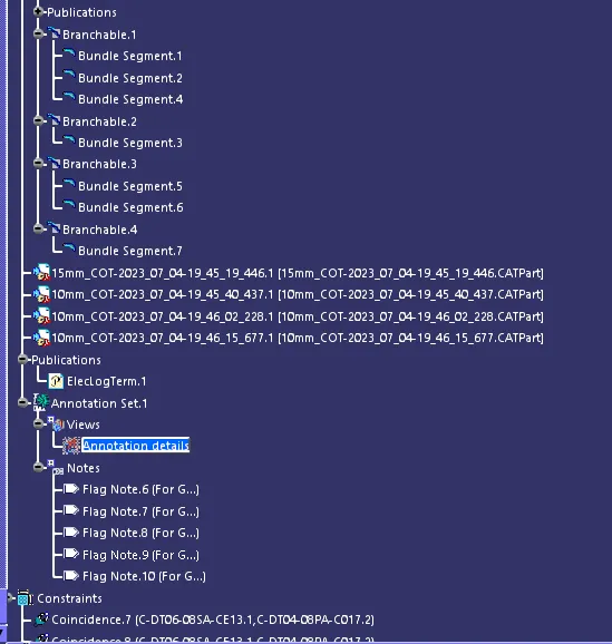
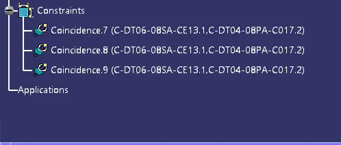
Product Assembly Image
..................
Note: All the CATPart files, Catalog files, Assembly files, CATPart of Harness Assembly and .igs file and .stp file are uploaded into a Single ZIP file and attached.