Week 2:- BiW Fixture Basics Challenge
Week 2:- BiW Fixture Basics Challenge
Q1. What is the process of project execution activity?
ANS:
The most important phase in project management is the project execution activity, which is where the project plan is carried out. It involves putting the project's tasks, actions, and processes into practice in order to accomplish the project's goals. The following are the key steps and components of the project execution process which is shown in the flowchart below.
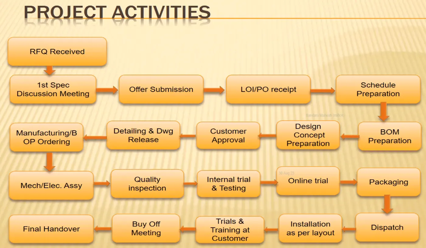
- RFQ Received: It is the project's beginning stage. Request for Quotation is referred to as RFQ. In the form of data or a paper, the client sets the project's requirements and specifications. The customer also specifies the technical offer, the commercial offer, and the project completion schedule.
- 1st Spec Discussion Meeting: The technical offer, commercial offer, and timeframe documents are created after receiving the customer's RFQ. The schedule takes into account the time needed for design, simulation, production, and client installation.
- Offer Submission: The completed document is then given to the client for review, so they can see if the parameters are met and if the deadline is reasonable and workable for them.
- LOI/PO Receipt: The customer will review the submitted information. In addition, the consumer obtains documents from different businesses, analyzes them, and chooses the best deal based on their needs. The work will begin after the customer selects the best bid and a purchase order is created. To maintain the deadline once they receive the PO, the project team works on it a little bit in the meantime.
- Schedule Preparation: After the PO is received, the project officially begins, and a timetable is created for each of its phases in order to finish it within the allotted time frame. The timetable is updated with all of the activities, including the period before PO receipt. To ensure that the entire project is finished by the customer-specified deadline, the time is divided and deadlines are set for each stage.
- BOM Preparation: The term "Bill of Material" (BOM) refers to the list of parts, such as motors and cylinders, that are needed for the project.
- Design Concept Preparation: Along with the LOI/PO outlining the requirements, the data is obtained, such as the 3D data from the automobile panel and the 2D designs from the customer. The design concepts are created using this information to satisfy the needs of the client.
- Customer Approval: After the customer-provided data is used to create the design concept. The customer is notified of the designed concept for approval. The customer examines the provided design to see whether or not it complies with the technical offer. The customer will approve the design if they are satisfied; otherwise, minor revisions will be made and the design will then be authorized
- Detailing and Drawing Release: The design drawings are released with all the relevant information, such as dimensions, tolerances, etc., once the customer has given their final approval following the completion of the necessary adjustments.
- Manufaturing/BOP Ordering: The design drawings are released with all the relevant information, such as dimensions, tolerances, etc., once the customer has given their final approval following the completion of the necessary adjustments.
- Mechanical /Electrical Assembly: The ordered parts go through quality control inspections before being checked for compliance with the necessary standards. The mechanical and electrical pieces are assembled in accordance with the design once the quality inspection is completed
- Quality Inspection: After assembly, a second quality inspection is conducted to see whether the dimensions are accurate and in accordance with the design data, coordinates, and measurements. Additionally, the relative sizes of the two pins are examined. For inspection purposes, CMM is employed.
- Internal Trail and Testing: After the assembly has received quality approval, internal trial and testing is carried out, during which the assembly is placed into the fixture and checked to see if the clamping is in the right place and that the pins are in the right positions. During the trial, welding, loading, and unloading operations are also put to the test.
- Online Trail: In the online trial, everything is carried out automatically using the control panel, and it is verified that the order of operations follows the specification. After the online trial, the buyer approves the part.
- Packaging and Dispatch: Following the online trial, the customer must authorize. He requests that the group ship the component for installation. The fixture is properly packaged to prevent damage during transit of the fixture, both visually and functionally. The fixture is sent to the customer after it has been packaged.
- Installation as per layout: At the very beginning, a layout will be created to demonstrate where the robot will be mounted and where fixtures will be mounted. This layout was created to meet the customer's functional needs.
- Trials and Training at the customer: There will be a trial at the customer's location following the installation. The purpose of production trials is to determine whether the quality standards are reached and whether the quantity of units processed by the fixture satisfies the requirement. Following that, training is provided to the engineers and operators at the customer end regarding the controls and the operating procedure.
- Buyoff meeting and Final Handover: The customer will confirm that all requirements have been met and that the advertised standard is in fact accessible. The project is eventually given to the buyer if they are satisfied with the part after making a few minor adjustments.
............................................................
Q2. What are the types of joining processes?
ANS:
Methods for connecting or bonding two or more materials together are called joining processes. These procedures are crucial in a variety of fields, including manufacturing, building, and engineering, where it is frequently necessary to join materials in a solid and dependable way. There are different kinds of joining procedures, each one suitable for particular materials and uses.
The durability and performance of any structure is largely dependent on the quality and the design of the component joints.
As the whole structure can not be made in one piece we use joining processes to join the objects.
They are two fundamental options for joining materials and components
-
- Metallurgical joining.
- Mechanical joining.
Some of the Metallurgical Joining are classified into
- Welding
- Brazing
- Soldering
-
Welding: Welding is a widely employed joining process that involves melting the materials at the joint and allowing them to solidify, creating a strong bond. Different welding methods include:
- Arc Welding: The processes involves either consumable or a non consumable electrode (rod or wire). An arc produced between tip of the electrode and work piece to be welded, by use of an AC or a DC power supply.
- Types of arc welding:
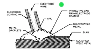
- Manual metal arc welding: Manual metal arc welding (MMA or MMAW) also known as Shielded metal arc welding(SMAW), or informally as stick welding. Stick welding is a process where the arc is struck between the metal rod (electrode flux coated) and the work piece, both the rod and work piece surface melt to create a weld.
- Gas-shielded metal arc welding (Metal inert gas (MIG) welding): Metal Inert Gas (MIG) Welding is an arc welding technique in which a consumable electrode is used to weld two or more work pieces. MIG Welding makes use of the following components:
•Consumable Electrode
•Inert Gas Supply
•Welding Head
•A.C or D.C Power Supply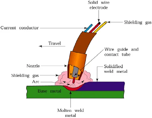
- Gas-shielded tungsten arc welding (Tungsten inert gas (TIG) welding): Tungsten Inert Gas Welding (TIG Welding), also known as Gas Tungsten Arc Welding (GTAW), is an arc welding method that uses a non-consumable tungsten electrode to weld two or more workpieces. It is very much similar to Metal Inert Gas (MIG)
Welding. The following components are necessary to perfer Tungsten Inert Gas Welding:
•Power supply
•Non-Consumable tungsten electrode
•Inert Gas Supply
•Filler rod (depend on the nature of work piece)
•Welding Head
- Manual metal arc welding: Manual metal arc welding (MMA or MMAW) also known as Shielded metal arc welding(SMAW), or informally as stick welding. Stick welding is a process where the arc is struck between the metal rod (electrode flux coated) and the work piece, both the rod and work piece surface melt to create a weld.
- Types of arc welding:
- Arc Welding: The processes involves either consumable or a non consumable electrode (rod or wire). An arc produced between tip of the electrode and work piece to be welded, by use of an AC or a DC power supply.
-
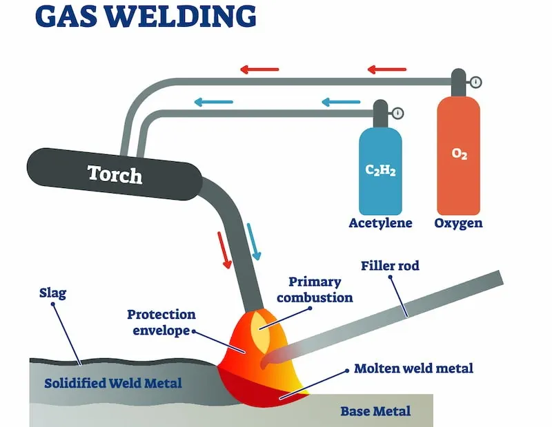
- Gas Welding: A high-temperature flame is created during the welding technique known as "gas welding," often referred to as "oxyfuel gas welding," by combining fuel gas and oxygen. The metal pieces that need to be linked are exposed to this flame, which causes them to melt and fuse together.
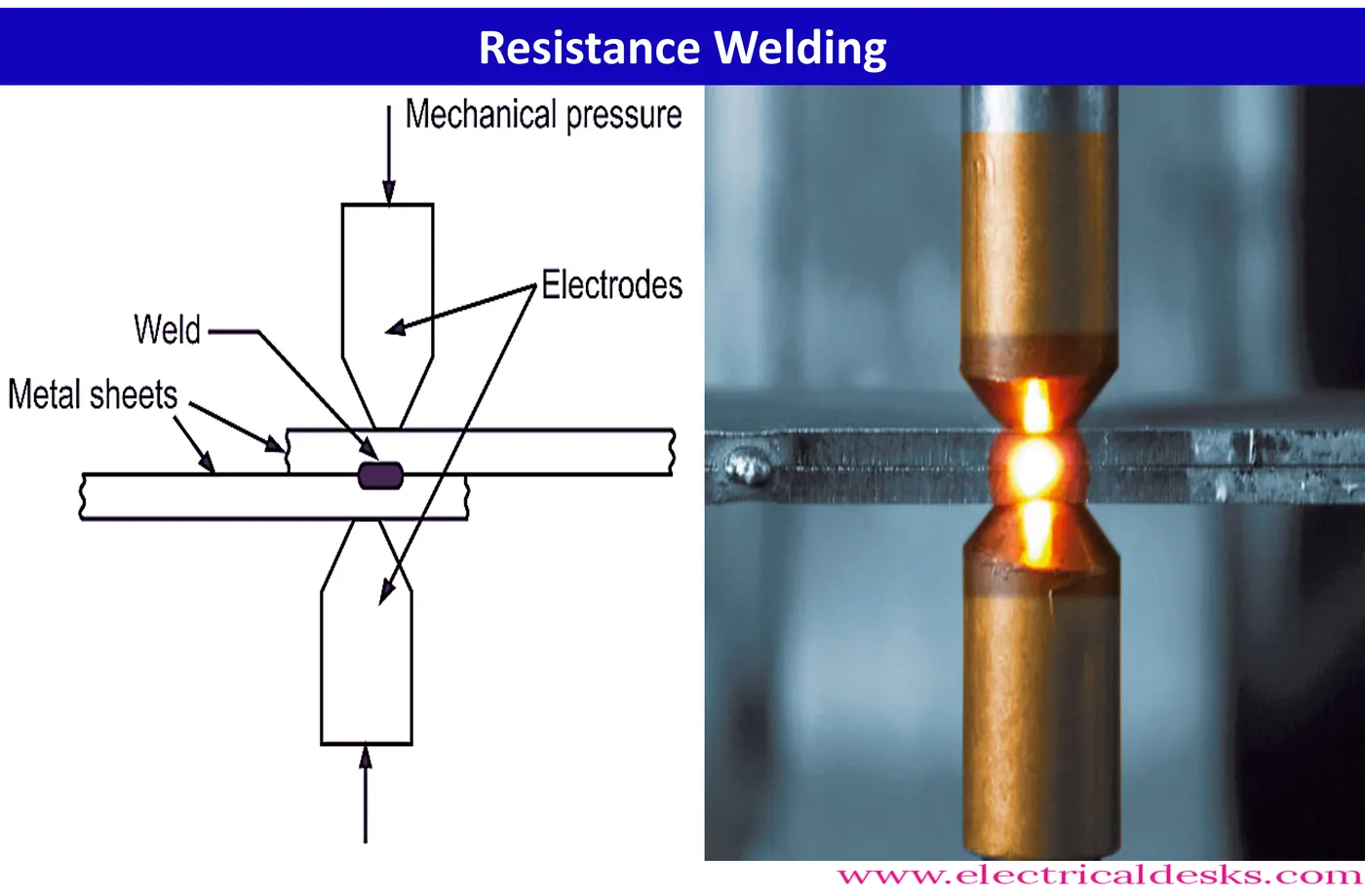
- Resistance Welding: Resistance welding is a welding technology widely used in manufacturing industry for joining metal sheets and components. The weld is made by conducting a strong current through the metal combination to heat up and finally melt the metals at localized point(s) predetermined by the design of the electrodes and/or the workpieces to be welded. A force is always applied before, during and after the application of current to confine the contact area at the weld interfaces and, in some applications, to forge the workpieces.
- Gas Welding: A high-temperature flame is created during the welding technique known as "gas welding," often referred to as "oxyfuel gas welding," by combining fuel gas and oxygen. The metal pieces that need to be linked are exposed to this flame, which causes them to melt and fuse together.
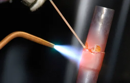
- Brazing: In brazing, two or more metal pieces are joined together using a filler metal that melts at a lower temperature than the base metals being joined. The process involves heating the assembly to a specific temperature, allowing the filler metal to flow into the joint, and then cooling to solidify the bond. Brazing creates strong, reliable connections and is often used in situations where welding may not be suitable due to lower heat input and the ability to join dissimilar metals.
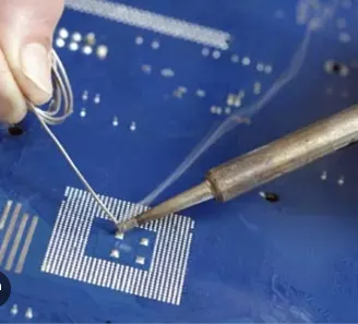
- Soldering: Soldering is a joining process similar to brazing, but it typically involves lower temperatures and a filler material known as solder. In soldering, two or more metal components are joined together by melting a lower-melting-point metal alloy (solder) and allowing it to flow into the joint between the base materials. Once the solder cools and solidifies, it forms a permanent, electrically conductive, and often hermetically sealed connection between the parts.
Mechanical Joining: Mechanical joining involves joining materials using mechanical components such as screws, bolts, nuts, rivets, or other fasteners. This method allows for disassembly and reassembly and is common in construction and automotive applications.
-
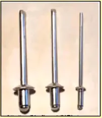
Riveting: Using a rivet, a cylinder-shaped fastening, to unite materials is known as riveting. To produce a secure connection, the rivet is inflated or bent after being put into a hole in the materials.

-
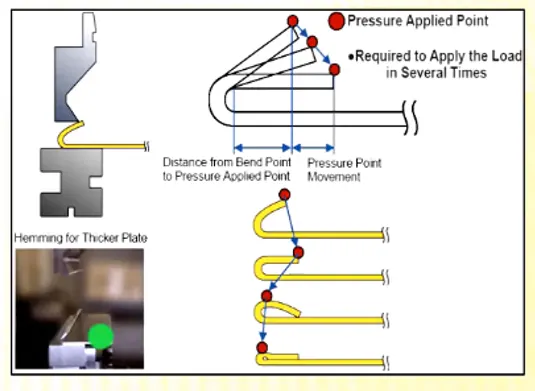
Hemming: Hemming is the folding of the sheet metal's edges to produce safe, rounded edges. The inner and outer panels of the BIW sections are typically wrapped with hemmed edges.
- Bolting: Bolts, screws, and nuts are used to assemble the metallic components in this joining process. This method is frequently employed in the assembly of pieces that must be temporarily linked or joints that need routine maintenance.

Adhesive Bonding: Adhesive bonding is a method of attaching materials in which an adhesive is positioned between the faying surfaces of the components known as adherents. Similar to soldering and brazing of metals, adhesive bonding prevents the formation of a metallurgical bond even when the surfaces being joined may be heated but not melted. Cement, glue, mucilage (sticky secretions from plants), or a paste are all examples of adhesives. Although there are organic and inorganic natural adhesives, synthetic organic polymers are typically used to adhere metals together.
............................................
Q3. What is Resistance Welding & its application in the automotive sector?
ANS:
Resistance Welding:
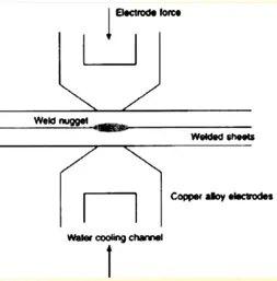
- Resistance welding is a welding technology widely used in manufacturing industry for joining metal sheets and components.
- The weld is made by conducting a strong current through the metal combination to heat up and finally melt the metals at localized point(s) predetermined by the design of the electrodes and/or the workpieces to be welded.
- A force is always applied before, during and after the application of current to confine the contact area at the weld interfaces and, in some applications, to forge the workpieces.
Type of resistance welding
- Resistance spot welding
- Resistance seam welding
- Resistance projection welding
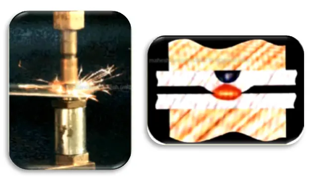
- Resistance Spot Welding: The process is used for joining sheet materials and uses shaped copper-chromium or zirconium alloy electrodes to apply pressure and convey the electrical current through the workpieces. Heat is developed mainly at the interface between two sheets, eventually causing the material being welded to melt, forming a molten
pool, the weld nugget. The molten pool is contained by the pressure applied by the electrode tip and the surrounding solid metal.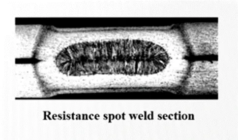
- Advatages:
- Short weld time and hence high weld speed.
- Highly adaptable to automation and robotic techniques.
- Typical BIW contains welds.
- Strength and durability of automobile largely depends on quality of RSW.
- Application: Resistance spot welding is typically used when joining particular types of sheet metal, welded wire mesh, or bare wire mesh.

- Advatages:
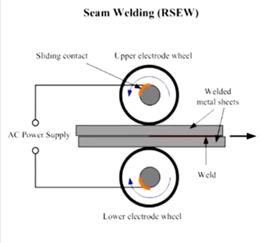
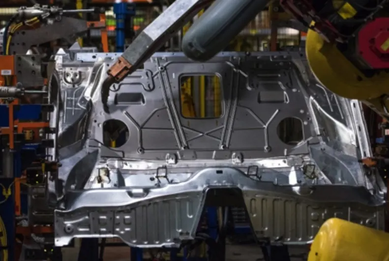
- Resistance Seam Welding: Seam welding is a resistance welding process for joining metal sheets in continuous, often leak tight, seam joints by directly applying opposing forces with electrodes consisting of rotary wheels. The current and the heat generation are localized by the peripheral shapes of the electrode wheels.
- Application:
-
Resistance seam welding can be used to make gas- or fluid-tight joints in a variety of sheet metal fabrications. Steel fuel tanks for motor vehicles are a prime example. It is also used in making tin cans, steel drums and domestic radiators.
-
- Application:
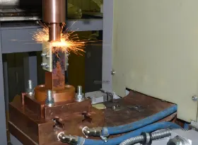
- Resistance Projection Welding: Projection welding is a resistance welding process for joining metal components or sheets with embossments by directly applying opposing forces with electrodes specially designed to fit the shapes of the workpieces. The current and the heat generation are localized by the shape of the workpieces either with their natural shape or with specially designed projection. Large deformation or collapse will occur in the projection part of the workpieces implying high.
- Application:
- Resistance welding is used in various applications, from consumer goods to heavy industrial components. Automotive parts such as exhaust systems and radiators are often welded using this method due to their speed and efficiency benefits.
- Resistance welding is used in various applications, from consumer goods to heavy industrial components. Automotive parts such as exhaust systems and radiators are often welded using this method due to their speed and efficiency benefits.
- Application:
..............................................
Q4. What is fusion welding & types of fusion welding with its application in the automotive sector?
ANS:
Fusion welding is typically used to fuse similar material combinations or components from the same family. It involves localized melting and solidification. Simply melting the edges of the two workpieces and allowing them to fuse together after cooling can create a weld in infusion welding. An autogenous weld is the name given to this kind of weld. The alternative method is melting a filler wire or electrode during the welding operation to add additional material. In both situations, the welded area will be different in terms of microstructure and characteristics from the source metal.
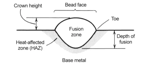
The fusion zone, a heat-affected zone (HAZ), and the base metal are the three main areas in a fusion weld, as illustrated below.
To maintain tolerances, distortion due to localized heating and cooling must be prevented or controlled by the use of jigs and fixtures.
Fusion welding is classsified into
- Gas Welding
- Arc Welding
- Thermit welding
- Gas welding: Oxyfuel welding, a form of chemical-based fusion welding, uses an oxygen fuel source to create a flame to heat and fuse surfaces. Of course, oxygen is necessary for fire, hence oxyfuel welding is based on this principle. The oxygen feeds the fire, causing it to burn hotter than 4,500 degrees Fahrenheit. When joining things, oxygen-fuel welding normally uses a mixture of oxygen and combustible gas to create a high flame.
In oxy-acetylene welding, a fuel gas (often acetylene) is burned in combination with pure oxygen to produce a high-heat, high-temperature flame. Using a flame from the combination of oxy-fuel gas through the tip of the welding torch, the base material is melted with the filler rod. Pressurized steel cylinders are used to store both the fuel gas and the oxygen gas. The cylinder's regulators lower the gas pressure. Flexible hoses carry the gas, and the welder uses the flame to control the flow.
The base material is then heated with the filler rod. However, using two pieces of metal without a filler rod is also feasible. It is employed in the automotive industry to weld frame and chassis components.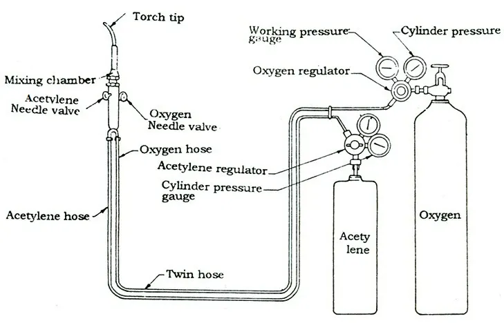
- Applications: Applications of gas weldingoxyacetylene welding can be used for joining carbon steels, alloy steels, cast iron, aluminum, and its alloys, copper and its alloys, nickel, magnesium, etc. Widely used in automotive and aircraft industries.
- Applications: Applications of gas weldingoxyacetylene welding can be used for joining carbon steels, alloy steels, cast iron, aluminum, and its alloys, copper and its alloys, nickel, magnesium, etc. Widely used in automotive and aircraft industries.
- Arc Welding: The processes involves either consumable or a non consumable electrode (rod or wire). An arc produced between tip of the electrode and work piece to be welded, by use of an AC or a DC power supply.
- Types of arc welding:
- Manual metal arc welding: Manual metal arc welding (MMA or MMAW) also known as Shielded metal arc welding(SMAW), or informally as stick welding. Stick welding is a process where the arc is struck between the metal rod (electrode flux coated) and the work piece, both the rod and work piece surface melt to create a weld.
- Gas-shielded metal arc welding (Metal inert gas (MIG) welding): Metal Inert Gas (MIG) Welding is an arc welding technique in which a consumable electrode is used to weld two or more work pieces. MIG Welding makes use of the following components:
•Consumable Electrode
•Inert Gas Supply
•Welding Head
•A.C or D.C Power Supply - Gas-shielded tungsten arc welding (Tungsten inert gas (TIG) welding): Tungsten Inert Gas Welding (TIG Welding), also known as Gas Tungsten Arc Welding (GTAW), is an arc welding method that uses a non-consumable tungsten electrode to weld two or more workpieces. It is very much similar to Metal Inert Gas (MIG)
Welding. The following components are necessary to perfer Tungsten Inert Gas Welding:
•Power supply
•Non-Consumable tungsten electrode
•Inert Gas Supply
•Filler rod (depend on the nature of work piece)
•Welding Head
- Manual metal arc welding: Manual metal arc welding (MMA or MMAW) also known as Shielded metal arc welding(SMAW), or informally as stick welding. Stick welding is a process where the arc is struck between the metal rod (electrode flux coated) and the work piece, both the rod and work piece surface melt to create a weld.
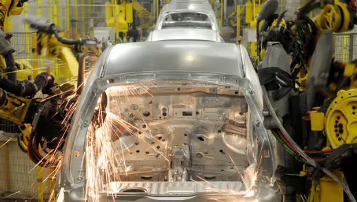
- Applications: Gas tungsten arc welding – Gas tungsten arc welding is ideal for automotive manufacturing projects when joining small parts and components. The method's versatility enables its use on both steel and alloyed metals and produces clean, high-quality welds for applications where aesthetics matter.
- Types of arc welding:
- Thermit welding: Thermit welding is a chemical welding process that uses heat from an exothermic chemical reaction to produce coalescence between metals. The process involves the burning of thermit, a mixture of fine aluminum powder and iron oxide in a ratio of about 1:3 by weight, which generates a temperature of 3000-degree Centigrade. Thermit welding is also known as exothermic welding, exothermic bonding, and thermite welding. It combines the process of welding and casting in which the molten iron is poured at the welding plates so that it can form a permanent strong joint. Thermit welding is used to join or merge two metals with the help of an exothermic reaction to form one mass or whole.
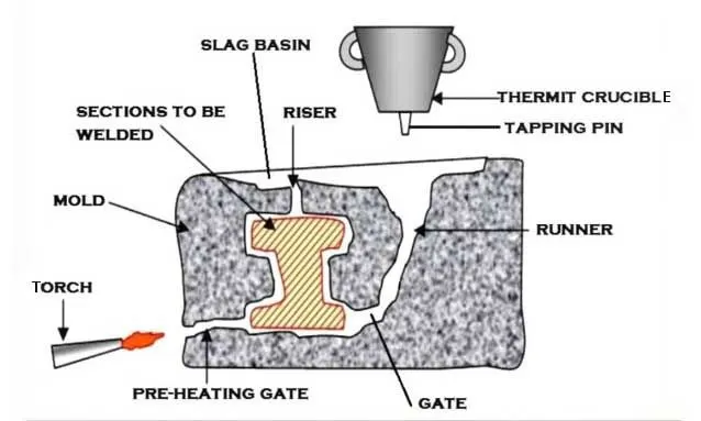
- Applications: To repair steel castings and forgings, for joining railroad rails, steel wires and steel pipes, for joining the large cast and forged parts, thermite welding is used.
.........................................................
Q5. What is the 3-2-1 principle?
ANS:
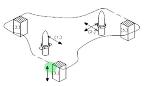
3-2-1 Principle: The 3-2-1 principle of location, also known as the six-point positioning principle, is used to constrain the movement of a workpiece along the three axes XX, YY, and ZZ. This principle is achieved by providing six locating points, including three pins in the base plate, two pins in the vertical plane, and one pin in a plane perpendicular to the first two planes.1 The principle states that the workpiece has six degrees of freedom in space, and six locators are sufficient to restrict the required degree of freedom of any workpiece. A three-pin base can restrict five motions, while six pins restrict nine motions.
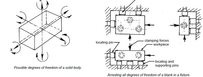
- The best and most cost effective method of part location is referred to as the 3-2-1 method.
- (3.) Minimum: three locator blocks to establish part plane. Three locators, or supports, are placed under the work piece. The three locators are usually positioned on the primary locating surface. This restricts one axial movement downward, and 4 radial movements. Together, the three locators restrict five degrees of freedom.
- (2.) Round locating pin in a round hole that defines location in four directions (4-way) perpendicular to the plane Previously established. This restricts four axial movement.
- (1 . ) Round locating pin in a slot that defines two of the directions of the other
pin (2-way).This restricts two axial movements
.......................................................
Q6. Define Body coordinate system?
ANS:
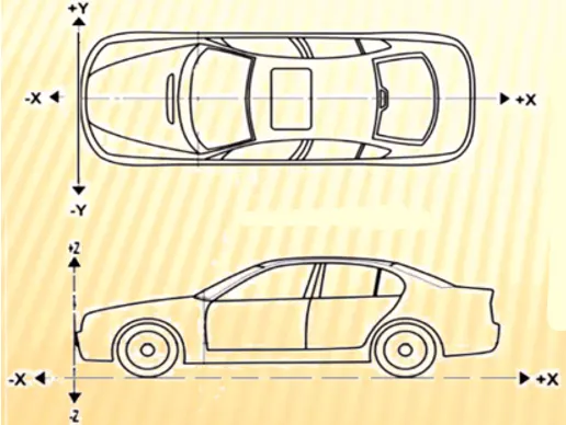
The body coordinate system has been widely used in the automotive industry for drawing of body parts, product and process design. A coordinate system is a reference system consisting of a set of points, lines and surfaces, used to define the positions Of points in space in either two or three dimensions. In general BCS is also called as car line and Body line.
X=Longitudinal direction [(Fore & After — F/A) or (Front O Line - FOL)]
Y=Transverse direction [(Cross car — C/C) or (center O line - COL)]
Z=Vertical direction [(Up & Down — U/D) or (Bottom O Line - BOL)]
The origin of the body coordinate system (OX) is defined at the front center of a vehicle, it indicates a length of car and the coordinate system (OZ) is below its underbody indicates height of car, and the coordinate system (O Y) its starting point is the center of car body indicates width of car.
Let's review an example in which the car's front end is where the axis system is located.
................................................................................
Q7. Elaborate Body plane system & its essentials.
ANS:
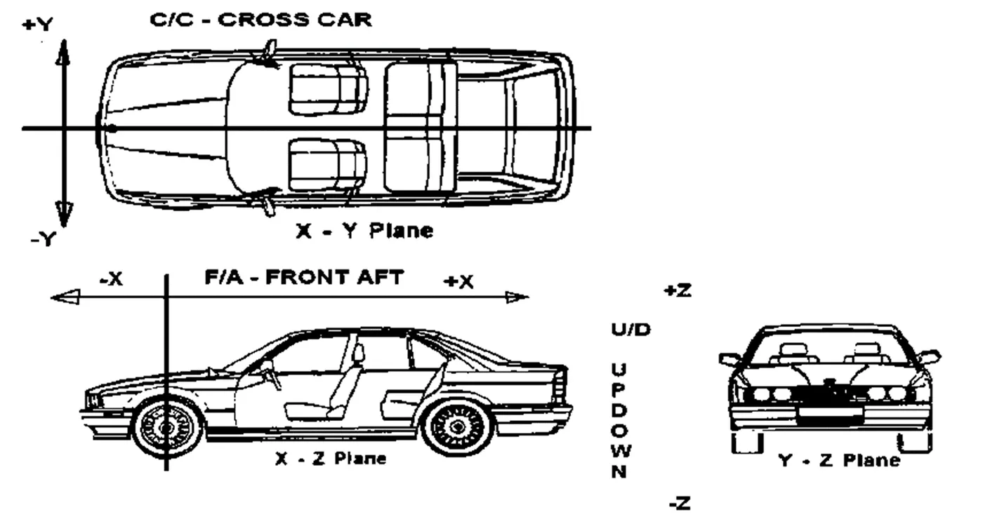
Body planes are the reference planes in an automotive car. These planes are used to define the GD & T of all car parts in a automotive domain. Body planes are 3 mutually perpendicular imaginary planes. These are generally considered to be present at the Driver position or sometimes at the engine location or at the front end of the car, depending on the customer. The Measurements from the body planes to the parts are called as bodyline dimensions.
These body planes are called as
- FOL Front "O" Line
- COL Centre "O" Line
- BOL Body "O" Line
- The Measurement along FOL or X axis is called as F/A Front Aft
- The Measurement along COL or Y axis is called as C/C Cross Car
- The Measurement along BOL or Z axis is called as U/DUP Down
Bodyline dimensions are essential for the reasons stated below,
- It defines the exact position of each product in the vehicle w.r.t. a fixed origin.
- It ensures flawless design for assembly.
- While designing lines, all the designs are carried out relative to the bodyline, viz. ,fixtures, turn tables, etc.,
- It assists in easy location of different parts in a vehicle.
- It aims in creating a standardized system.
- It assists in Quality Checks.
...........................................................