Week 9 - Challenge 1 - Base Bracket Design
BASE BRACKET DESIGN
Objective:
By using the provided Class-A surface, creating the Base Bracket Plastic component by Creating the tooling axis for the supplied Class A Surface according to the draft angle specifications and then do the Draft analysis on the Solid Model. Before creating a solid component it's always better to check the draft angle for the given Class A Surface.
When designing plastic components, CAD software like CATIA creates a surface model of the desired final shape. The following steps are often included in the process:
- Identify the component's purpose, as well as its size, shape, material, and any other important criteria, to define the component's needs.
- Create a digital surface model of the component using CATIA software, making sure to include all the necessary details including holes, ribs, bosses, and other design aspects. A series of mathematically defined curves and surfaces are used to generate the surface model, which is a smooth and exact representation of the final design.
- Performing draft analysis: This involves analyzing the surface model to determine the optimal angle of the draft for the part, which is the degree to which the walls of the part are tapered to facilitate its removal from the mold after the plastic injection process. This is an essential step that ensures that the final product is of high quality, and the manufacturing process is efficient.
- Creation of tooling axis: This involves creating a path for the cutting tool that will be used to machine the mold for the component. The tooling axis determines the quality of the final product, the efficiency of the machining process, and the overall cost of production.
The tooling axis can be created using various methods, including the Bisecting method. The Bisecting method is a simple and efficient tooling axis creation method that involves creating a plane that bisects the part and aligning the tool axis perpendicular to that plane. This method is commonly used for symmetric parts that require machining on both sides. The process involves creating a surface model of the part using CATIA software, determining the symmetry plane of the part, creating a plane that bisects the part perpendicular to the symmetry plane, and aligning the tool axis perpendicular to the bisecting plane.
In conclusion, designing plastic components involves several critical steps, including creating a surface model, performing draft analysis, and creating a tooling axis. The Bisecting method is a popular tooling axis creation method that is widely used due to its simplicity and efficiency. By following these steps, manufacturers can ensure that the final product is of high quality, the manufacturing process is efficient, and the overall cost of production is optimized.
TOOLING AXIS:
In the process of plastic injection moulding, the tooling axis is extremely important. It establishes the part's orientation within the mould, which has an impact on the final product's mechanical qualities. The strength, durability, and aesthetic appeal of the item may be endangered by internal stresses, warping, or other problems caused by improper tooling axis alignment. Additionally, a misaligned tooling axis can lead to increased tool wear, longer machining times, and higher costs. Therefore, it is crucial to optimize the tooling axis to produce high-quality plastic components that follow the necessary criteria while reducing production costs.
The tooling axis also has an impact on manufacturing costs and overall productivity. Manufacturers can cut the time and expense needed to make high-quality plastic components by designing an ideal tooling axis. The mold's essential features must be accessible to the cutting tool without causing harm to either the component or the tool itself. A cutting tool may efficiently machine the mould with the help of a properly aligned tooling axis, resulting in a shorter cycle time and less tool wear. As a result, by optimizing the tooling axis, the entire cost of production can be reduced while also guaranteeing that the finished product meets the necessary criteria.
BISECTING METHOD: The Bisecting method is a commonly used technique in the plastic injection molding industry for creating a tooling axis for symmetric parts. The method involves creating a plane that bisects the part and aligning the tool axis perpendicular to that plane. This approach is simple and efficient, making it an attractive option for manufacturers looking to optimize their production process.
To apply the Bisecting method in CATIA, the first step is to create a digital model of the part using the software's surface modeling capabilities. The symmetry plane of the part is then determined, and a plane is created that bisects the part perpendicular to the symmetry plane. Finally, the tool axis is aligned perpendicular to the bisecting plane, ensuring that the cutting tool can access all the necessary features of the mold without damaging the part or the tool itself. The Bisecting method is especially useful for symmetric parts that require machining on both sides, as it allows for efficient machining while ensuring that the final product is of high quality. By utilizing this technique in CATIA, manufacturers can reduce production time and costs while still producing high-quality plastic components that meet the required specifications.
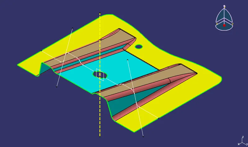
Steps that have been followed to Create the Tooling Axis
- To create the Tooling axis using bisecting method we have to analyze the best tooling direction first and then we have to create the point where the tooling axis is needed.
- create a dummy tooling axis(Yellow Axis Line) on the point in the top direction to the surface and create a plane so that we can intersect the Class A Surface.
- After that, we have to create the intersection and generate the lines around the Class A Surface.
- Then find the lines that can be found as same on both sides. (This can be found mostly in symmetric parts.)
- now create the lines by using the line option regarding the intersection.
- Finally by using both lines create the Tooling Axis (Cyan Axis Line) with the help of bisecting option in line Command.
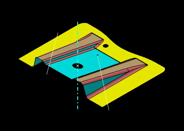
DRAFT ANALYSIS:
Draft analysis is a critical step in the plastic injection molding process that is essential for ensuring the production of high-quality plastic components. In the industrial sector, draft analysis is often referred to as parting line analysis, and it involves analyzing the 3D model of a plastic component to determine the optimal angle of the draft for the part.
The draft angle, also known as the taper angle, is the degree to which the walls of the part are tapered to facilitate its removal from the mold after the plastic injection process. This is an important consideration in the design of plastic components, as it can affect the quality of the final product and the efficiency of the manufacturing process. The draft analysis process in CATIA involves analyzing the 3D model of the part to determine the optimal draft angle for each feature of the part. The software identifies any areas of the part where the draft is insufficient, and it suggests modifications to ensure that the part can be removed from the mold without damage.
By performing a draft analysis in CATIA, manufacturers can ensure that their plastic components are of high quality and can be produced efficiently. The software provides advanced simulation capabilities that allow designers to identify and correct any issues with the draft angle before production begins. This ensures that the final product meets the required specifications and that the manufacturing process is optimized for cost and efficiency.
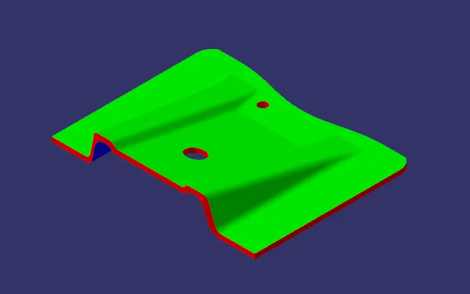
Image of Draft Analysis on Class A Surface
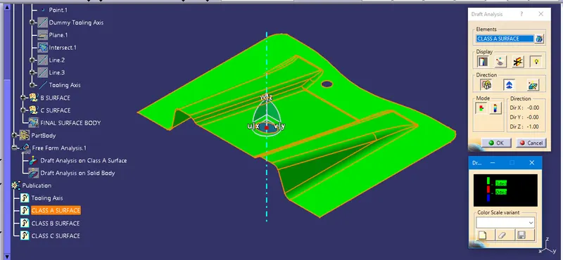
Steps that are involved in checking Draft analysis on Class A Surface:
- Initially Click on the Class A Surface and publish it.
- Then click on draft analysis and adjust the compass to the point that we have created on the tooling axis.
- Now lock the direction and Check the angle on the Class A Surface. (Ensure to keep the upper angle limit to 3 deg)
Image of Draft Analysis on Solid Body
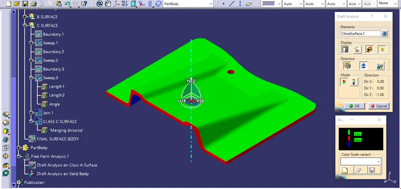
Steps that are involved in checking Draft analysis on Solid Body:
- Initially Click on the Solid Body.
- Then click on draft analysis and adjust the compass to the point that we have created on the tooling axis.
- Now lock the direction and Check the angle onto the Solid Body. (Ensure to keep the upper angle limit to 3 deg)
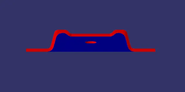
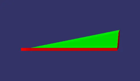
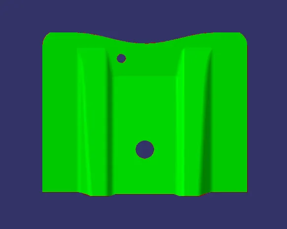
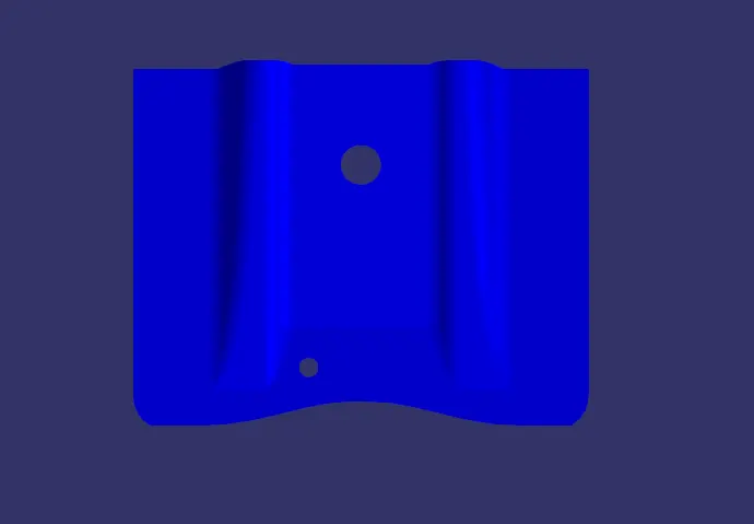
images of Draft Analysis of the Solid Body in Different Orientations
Front View
Side View
Top View
Bottom View
Isometric View
............