Fender Design
FENDER DESIGNING OF A CAR:
1.) Introduction to Fender:
The section of a car, motorbike or other vehicle body that frames a wheel nicely is known in American English as a "Fender". Its main objective is to stop the revolving tires from launching debris including sand, dirt, gravel, liquids, and other road sprays into the air. Since fenders are usually inflexible, contact with the road might harm them.
As the tires roll over the ground, sticky substances like mud may stick to the smooth outside tire surface, while soft, loose things like stones may become embedded in the tread grooves. Given that the attached particles get a kinetic energy from the tires, these materials can be ejected off the tire's surface at a high rate of speed. The top of the tires on a moving vehicle rotates upward and forward and has the potential to launch things at oncoming traffic or pedestrians.

Image of Wagon R Fender
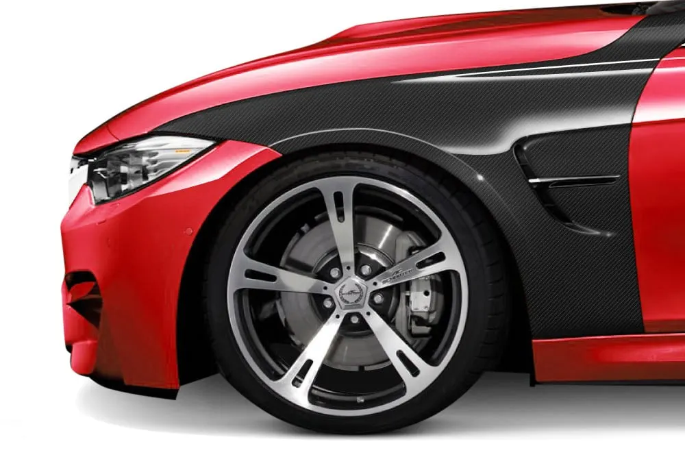
Image of Carbon-Fiber Fender of BMW
TYPES OF FENDER
- Full Bumper type
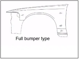
Older cars have full bumper fenders, which cover the entire area up to the front illumination. However, it contains a lot of extra sheet metal that adds to the fender's weight. Automobiles no longer have this style of fenders.
- Half Bumper type
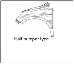
In cars, the half-bumper type is most common. Basically, it has to do with scrap management. A half-bumper type uses less paper than a full-bumper type. To lower the scrap rate per blank, we switched from full bumper type to half bumper type. In contrast to the half bumper type, where we can make two fenders per blank, the complete bumper can only produce one fender per blank.
Fender Mounting Region
- Bumper Area
- Drip Area
- A-Pillar Area
- Sill Area
- Cowl/Splash/Baffle Area
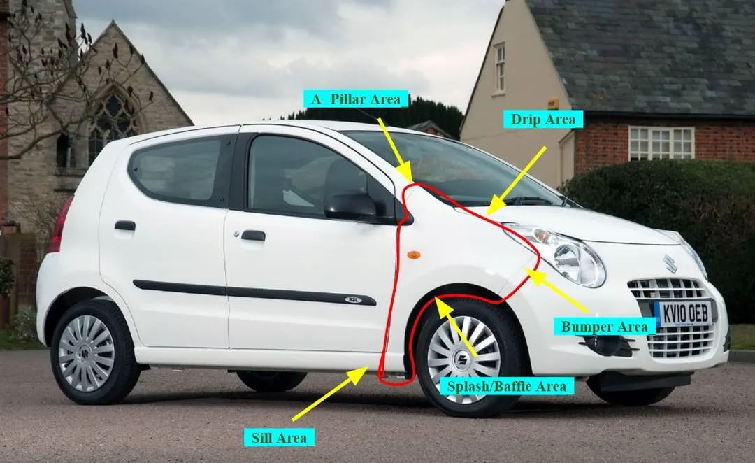
Image of A-star fender
2.) Data are given for Designing Fender:
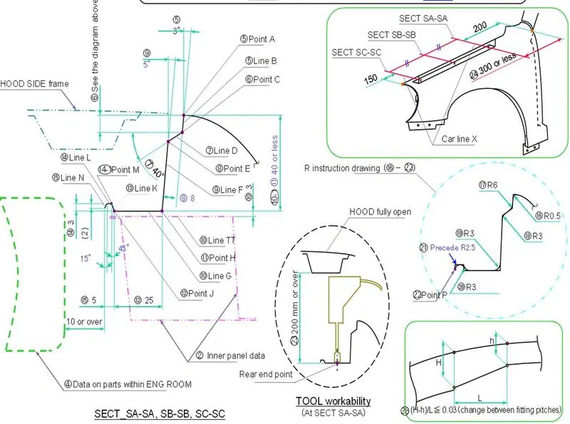
FIG 2.1: Section Data of fender
Fig 2.2: Drip Area Information
3.) Designing of Fender
DESIGN OF DRIP AREA MOUNTING :
- It is the fender's crucial uni. Because it is attached to the engine compartment, there are several design considerations that must be made when creating the fender.
- To account for the cowl top, we must first leave 200 to 300 mm while planning the drip.
- When creating the fender, we must leave at least 150 mm at the front for mounting the headlamp.
- The wiper motor and associated instruments are located in the cowl top section.
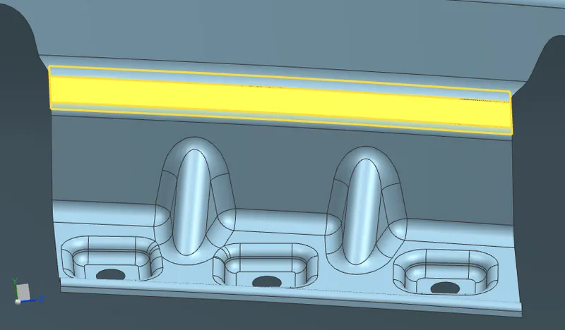
Drip area front section
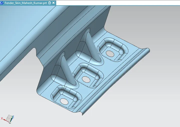
Drip Area View-2
SILL MOUNTING AREA DESIGN:
The sill, which connects the floor and the body, is the panel that supports the floor right beneath the bottom of the door. The sill mounting location is created with holes and emboss, and M5 fasteners are used to fix the fenders on the sill body. The bottom end of the fender is mounted to the sill body for reinforcement of the fender panel.
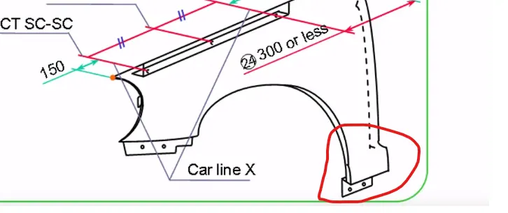
Reference Sketch
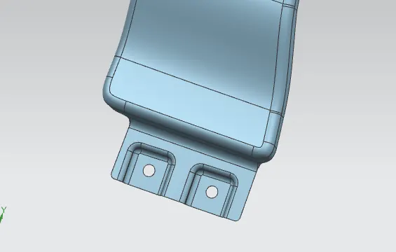
designed fender
BUMPER MOUNTING AREA DESIGN:
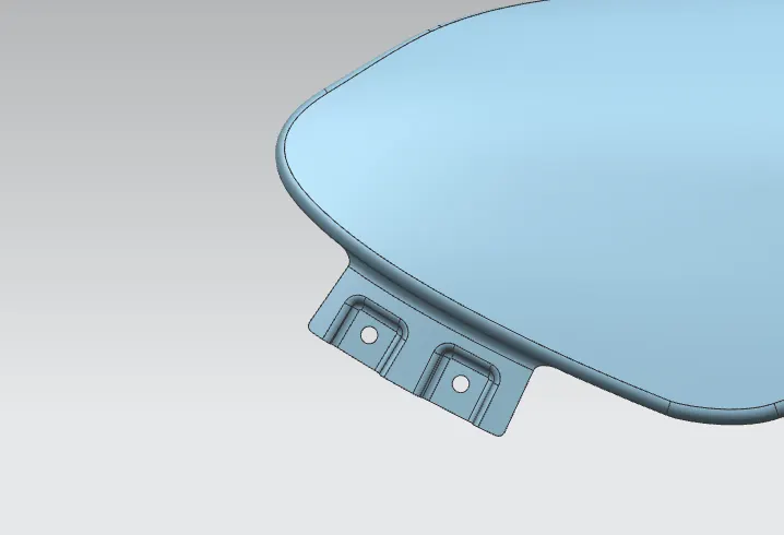
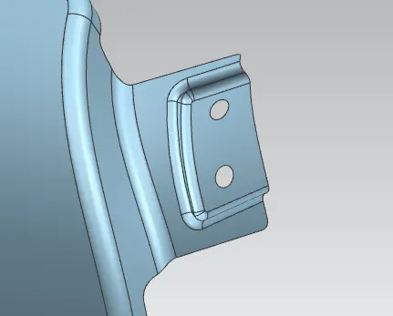
A-PILLER MOUNTING AREA DESIGN:
DESIGN OF BAFFLE MOUNTING AREA:
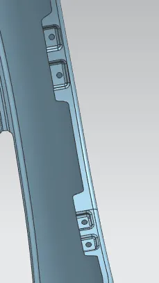
BAFFLE AREA VIEW 1
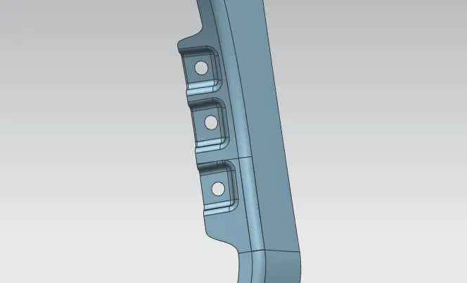
BAFFLE AREA VIEW 2
THE SURFACE IS BEING APPLIED WITH THICKNESS:
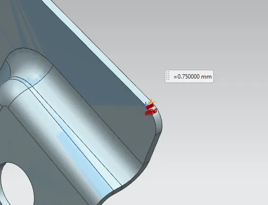
The final stitched surface of the fender has a thickness of 0.75 mm inside it according to sheet metal standards.
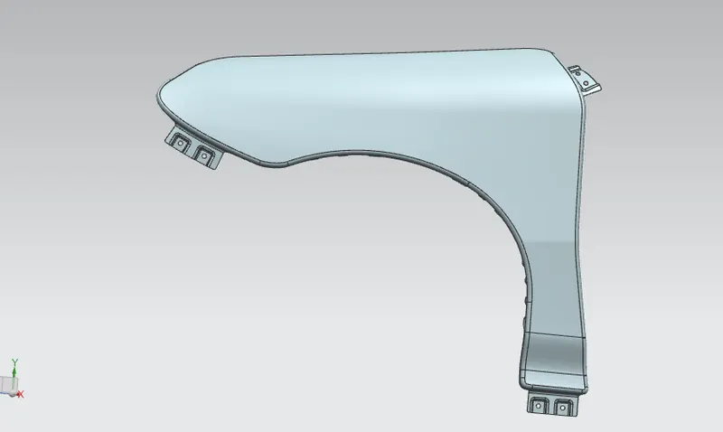
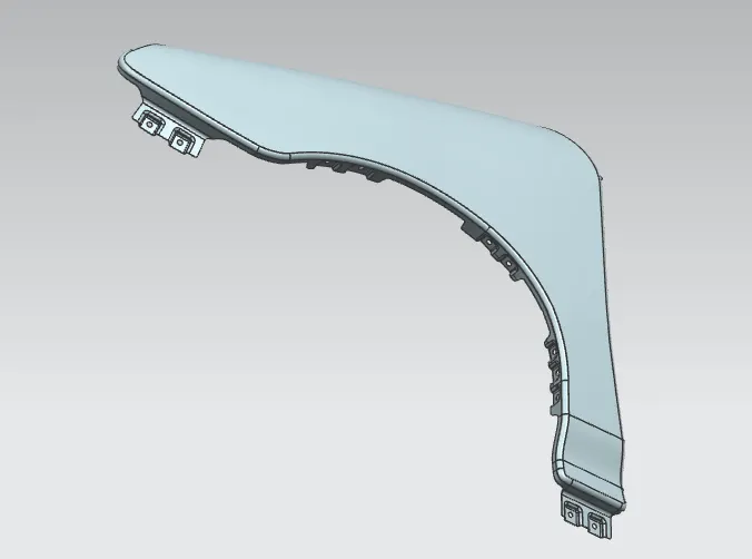
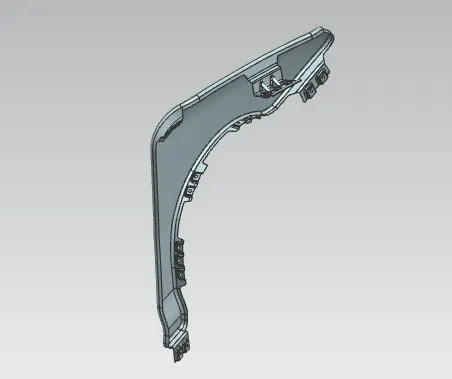
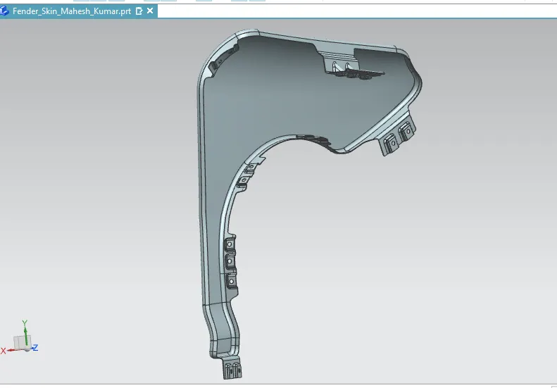
4.) DIFFERENT VIEWS OF FENDER :
CONCLUSION:
Finally, using NX-CAD software, the fender is designed while following the master section.