Hood design Using NX CAD
Designing of Hood using NX CAD
Objective:
- To design the Hood/bonnet of the car by using the master section provided in the challenge and using a standard procedure which is used by the OEM Manufacturers.
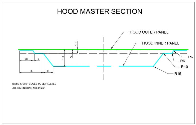
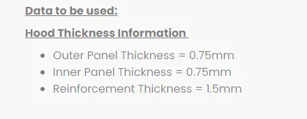
- Given data should be used to design the Hood model. The data provided is shown below
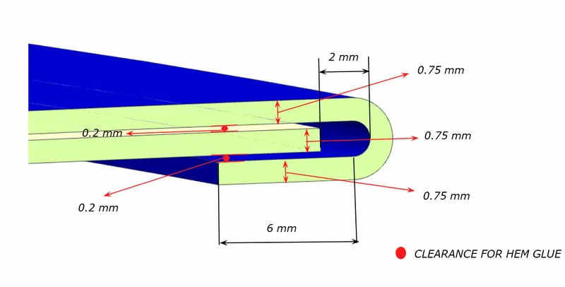
Hemming Data
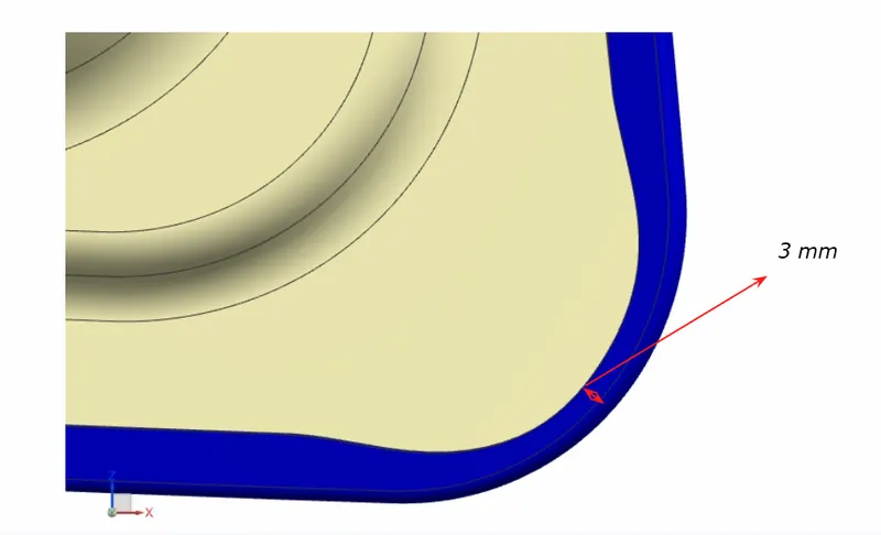
Relief rear section
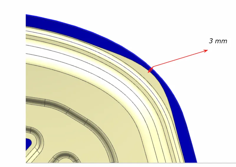
Front Relief Section
1.) HOOD:
The hinged cover above the engine of a car is called the hood or bonnet. For maintenance and repairs, hoods can be opened to provide access to the engine compartment or trunk (boot) on various mid-engine and rear-engine automobiles. In general, it includes the car's engine and other necessary components. Hood Inner Panel and Hood Outer Panel make up the Hood. The outer panel provides an attractive appearance, while the inner panel offers strength and support. A design engineer must ensure that the following design criteria are followed when creating the Hood are
Pedestrian Protection,
Employee Safety,
Styling \manufacturability.
Things to take into account when designing the hood:
N CAP crash test, the opening angle of the bonnet, Wrap Around Distance (WAD), and NVH (Noise, Vibration, Harshness).
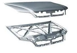 Outer panel and an inner panel of the bonnet.
The Hood has the following components:
- Outer Panel
- Inner Panel
- Striker
- Hinge assembly
- Reinforcement
- Mastic points
The Hood has been designed by the process of using the following Sheet Metal Operations:
- Hemming
- Embossing
- Deep Drawing
- Piercing
1.1) The outer panel
It is the most crucial component of the hood that gives the car a very pleasing aesthetic balance. To fulfill the aesthetic criteria, the outside panel must be correctly constructed. It also provides good aerodynamics. Therefore, those sheet metal procedures must strictly not be used to create the outer panel if the result is visible on the outer panel or if it lowers the aesthetic value. Because of this, hemming is employed to link the outer panel to the inner panel rather than welding.
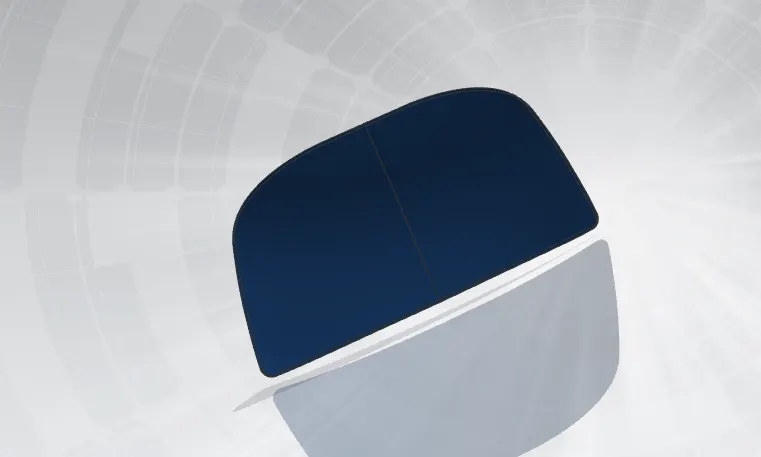
The outer panel has been constructed as shown below using the outer panel style surface and the supplied outer panel thickness (0.75mm).
1.2) Inner Panel:
When a collision happens, the inner panel, which is a key component in maintaining the hood's rigidity, is employed to deflect as much of the impact as it can to the hood's edges. It can be done by using a good inner panel design and the inner panel's embossing direction. In order to ensure passenger and driver safety and set standards, numerous design modifications and research projects have been undertaken. The necessary holes for moving the hood from one station to another and fixing the hood in a fixture are made in this inner panel. The embosses and mastic points are also present on the interior panel.
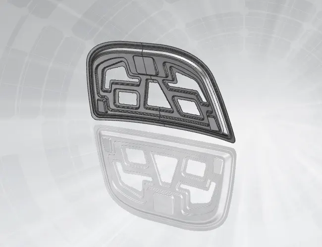
The Inner Panel has been constructed with the embosses and mastic points shown below by taking into account the Inner Panel thickness (0.75mm) and offsetting the outer panel style surface using the specified offset data.
1.3) Reinforcements:
The lower side of the inner panel is where the Striker and Hinges are joined. If it can be done directly, greater stress will be placed on that specific location of the inner panel, which could lead to the deformation of the panel there. so that the reinforcement enters and is positioned between the hinge, the hood, and the striker. It can reduce deformation while reinforcing the inner panel in that specific area.
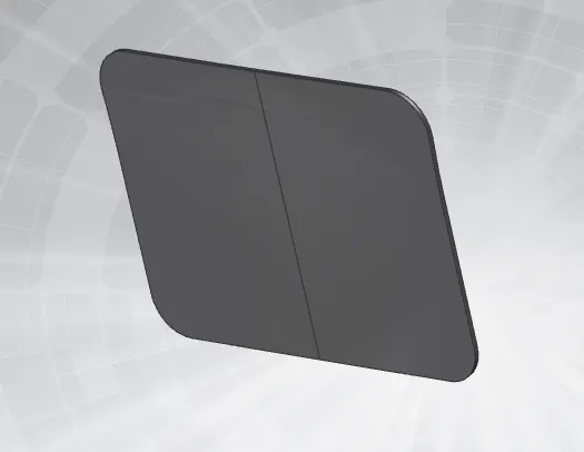
striker reinforcement
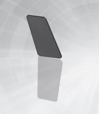 hinge reinforcement
1.4) Striker and Latch:
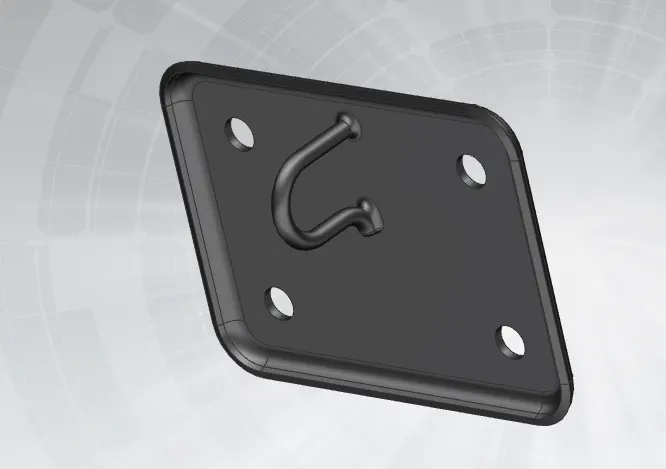
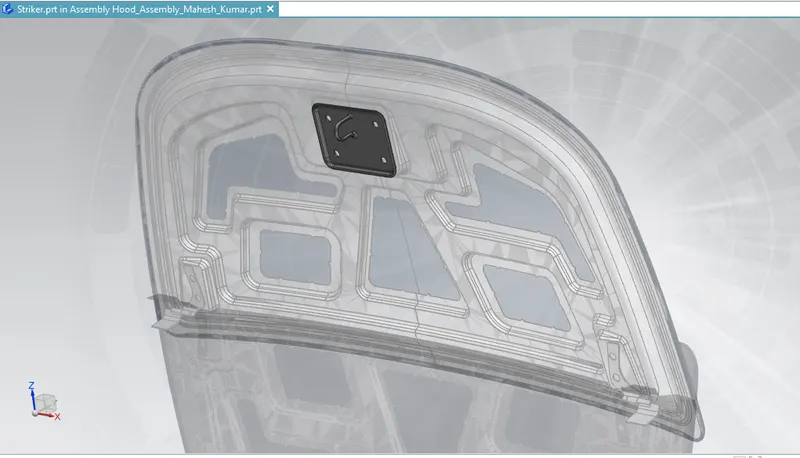
When the hood does not need to be opened, the striker is the component that is used to secure the hood to the engine compartment using the latch that is attached to the engine compartment. When the hood is lowered, the striker, which is fastened to the bottom of the inner panel, engages the latch and locks it.
The driver is given a lever within the cabin to release the pressure on the lock. Once completed, the hood will expand by one inch, allowing us to use it.
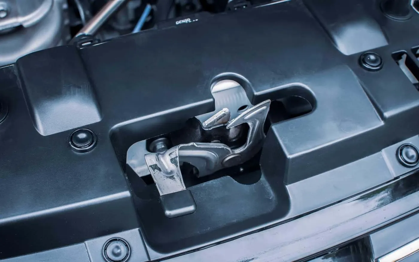 latch
latch
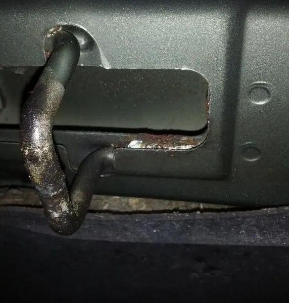 striker
The striker used in designing this hood:
1.5 )Assembly of Hinge:
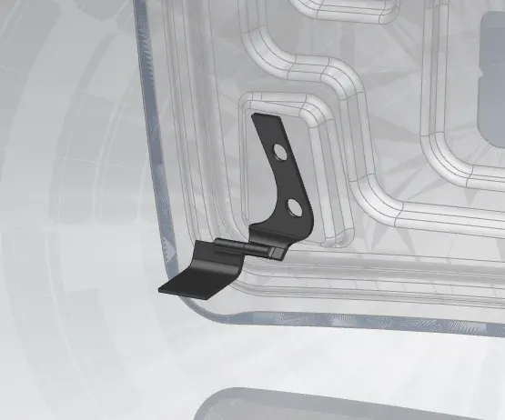
It is utilized to secure the hood to the engine bay. Hinge is essential for any component that has to open and close along an axis. It is put together using a single axis and has just two straightforward parts—a hood side hinge and an engine compartment side hinge. At the outer ends of the hood and engine compartment, hinge assemblies are fastened.
1.6) Position of Striker and Hinge Assembly
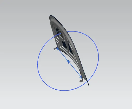
There are specific actions that must be taken in order to attach the striker to the inner panel of the hood. To accomplish this, the hinge is initially loosely linked to each outward end of the inner panel using the hinge reinforcement. The axis of the two hinges is then drawn as a line. At the intersection of that line's midpoint and its tangent, a circle is formed. The ref line is then drawn at a specific angle inside the circle. After that, the circle's diameter and linge angle were adjusted based on the needed striker position. From the striker's striking point, a second line has also been drawn parallel to the hook of the strike. Then, utilizing the assembly constraints, attach the striker reinforcement and both lines to the inner panel.
Hood Support: Based on the weight of the food there are two types of support
1. Support rod/stick
2. Gas Stay
some of the images have been provided below to understand better.
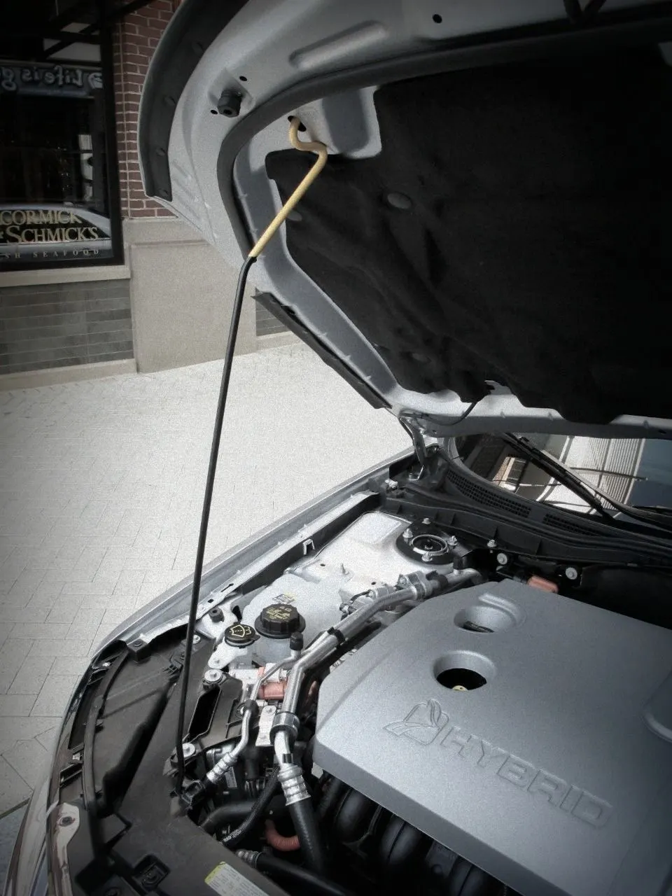
support rod/stick
gas stay support for the hood
Hemming:
The pieces are fitted together using hemming. It can be done by folding the edges of one portion over the other section and fixing it inside of it. The roller is used to complete this task.
Hemming is used to creating the hoods, doors, and boot lids of car parts.
There are two different hemming processes:
Traditional die hemming: In this technique, the sheet metal edge is folded by its whole length using a hemming die.
Roll Hemming: In this technique, rollers are used to complete the operation and two or more rollers simultaneously fold the sheet metal from various locations along the sheet metal edge to produce a hemming that is relatively exact. The majority of automakers use the roll hemming technique because it is simpler than the more traditional die hemming.
The edges of the outer panel are folded and rolled back to the underside of the inner panel during the hemming process in the Hood. The corner of the outside panel edge must be trimmed because, as the outer panel edge is folded and rolled back during the hemming process, there is a risk that the sheet metal would break.
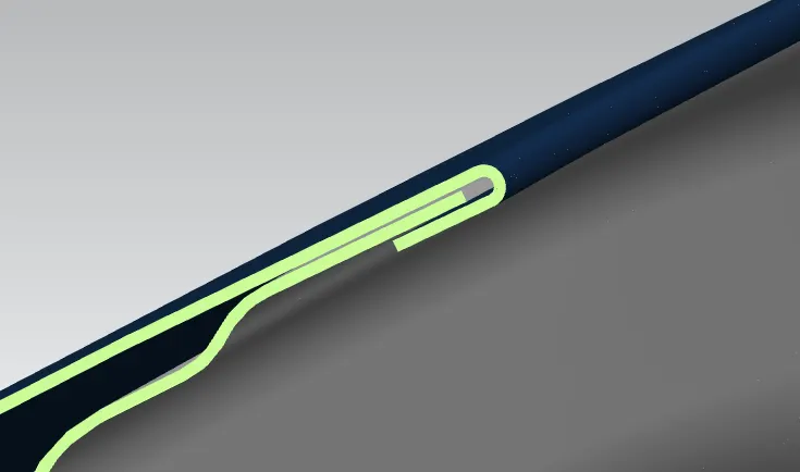
Hemming the surface of the Hood.
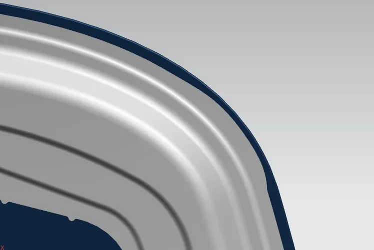
Front relief of the Hood.
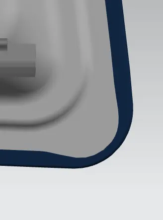
Rear Relief of the Hood.
Deep Drawing: Deep drawing is a sheet metal forming technique in which a sheet metal blank is mechanically pulled radially into a forming die. Thus, it is a shape-change process that keeps the material. When the drawn part's depth is more than its diameter, the procedure is referred to as a "deep" drawing.
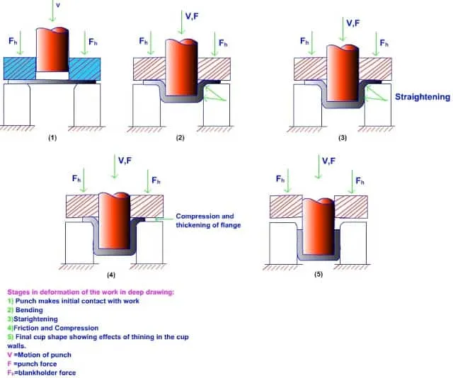
image of deep drawing
gif of deep drawing
Embossing:
Embossing is a kind of stamping process. It is the process of applying pressure to the flat sheet metal by the forming tool to create the projection on that sheet metal wherever required.
In the Hood design, the inner panel of the hood has more embosses to improve the strengthening of the panel. Based on the design structure, the embosses are created or we can say projected on the inner panel sheet metal.
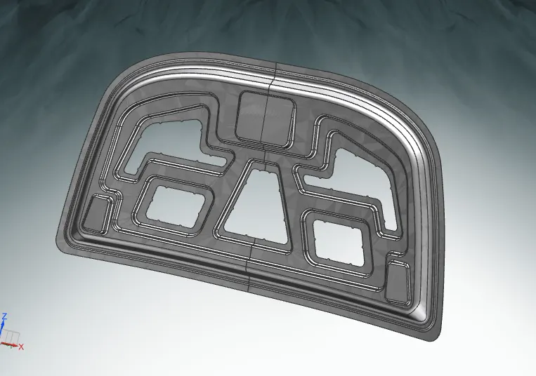
image of embossing for the hood
Piercing: Piercing is a type of shearing procedure in which undesirable parts of the sheet metal with certain forms are removed using a blanking punch and dies. Sheet metal punching is a method of metal fabrication that is widely utilized and is crucial to the contemporary industry. The procedure involves driving a punch die—a tool—through the sheet metal workpiece, which shears the metal and creates a hole as a result.
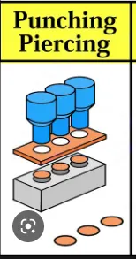 piercing image
Mastic points:
Mastic glue was created especially to join outer automotive panels, such as roofs, doors, and hoods, to the interior panel structure of the car. With this one-component synthetic rubber sealant, panel deformation and panel flapping are prevented and reduced. Hoods frequently have enormous surfaces, and the only way to hem one of them is through the boundary. Other joining methods, like welding and riveting, produce traces on the outside panel that detracts from its visual appeal, thus we are unable to use them. Therefore, the inner surfaces of the outer panel and inner panel are adhered to using mastic sealants. Mastic sealants are rubber-like elastic compounds. At predetermined locations, it is applied between the inner and outer panels. Each mastic sealant area has an 80mm diameter sphere that it affects. As a result, the mastic points are positioned so that they cover the more vibration-sensitive parts away from the hemming.
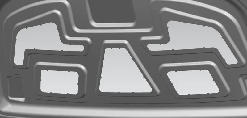
mastic points on the hood
On these small dots as shown in the figure mastic points will be arranged to observe the vibration that is produced by the car when it is in motion.
Considering pedestrian safety while designing the hood:
The zone or nation determines head clearance. Therefore, the opening angle of the same car built for a different country will vary depending on that country or location.
The graph in the image's top right corner shows the distance between points C and D as seen in the image. The angle of the hood opening is determined by selecting the proper head zone position.
The marketing team will provide advice to product developers as they choose the head zone.
Wrap around distance (WAD) of the car for the frontal crash:
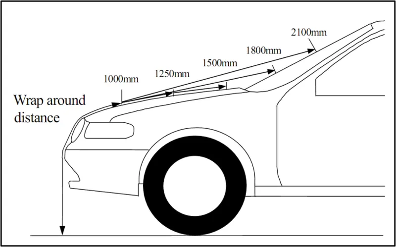
The type and shape of the vehicle, its speed, and how the pedestrian moves in relation to the vehicle all affect how severe the injuries brought on by a frontal collision are. In addition to these variables, the wrap-around distance is a crucial factor in determining how safe a pedestrian is. Two test areas—the Child head impact zone and the Adult head impact zone—will be developed during the accident investigation based on the Wrap Around Distance (WAD). The adult head impact zone spans from 1700 to 2100 mm WAD, while the kid head impact zone is within the range of 1000 to 1700 mm WAD.
2.) Assembly images of the hood:
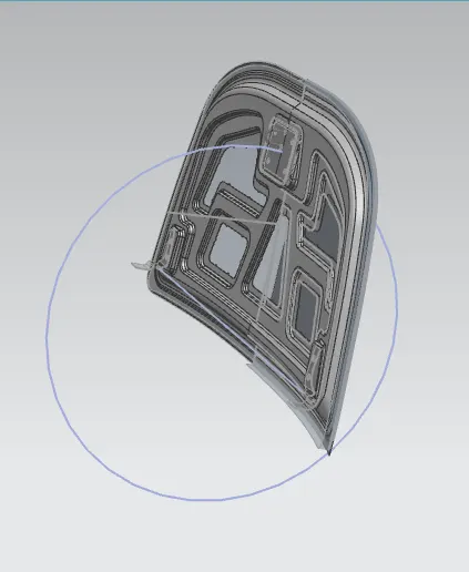
fig 2.1: Latch trajectory image
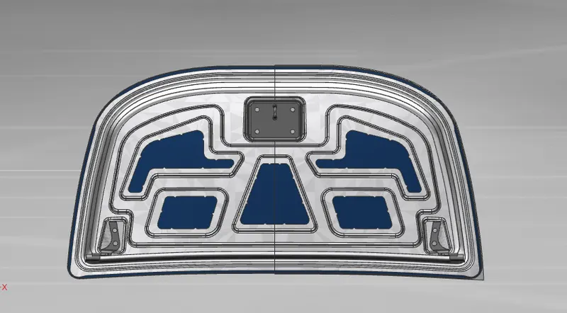
fig 2.2: front view of the hood assembly.
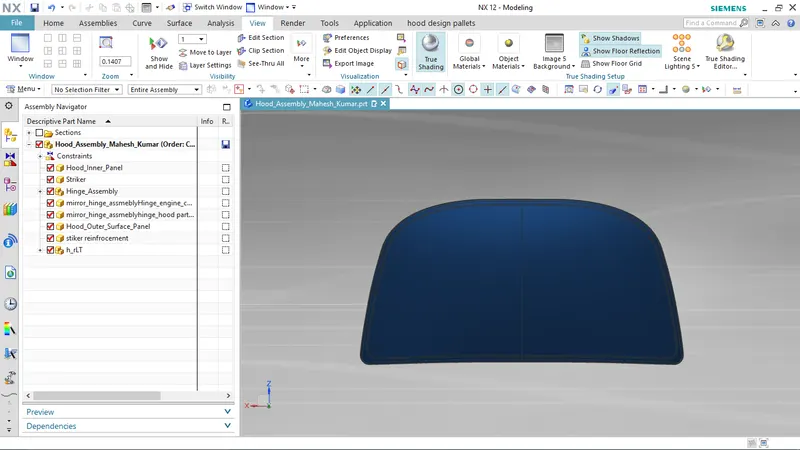
fig 2.3: back view of the hood assembly.
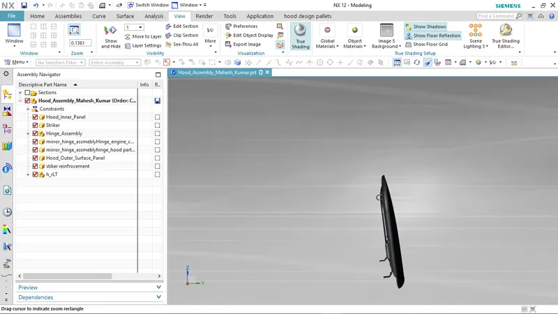
fig 2.4: side view of the hood assembly.
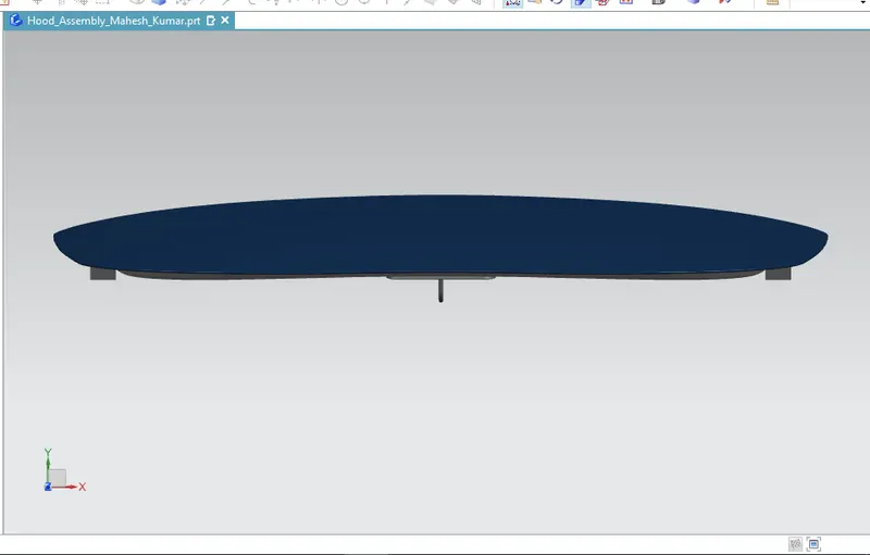
fig 2.5: top view of the hood assembly.
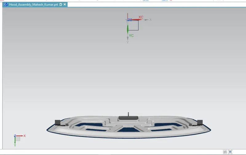
fig 2.6: bottom view of the hood assembly.
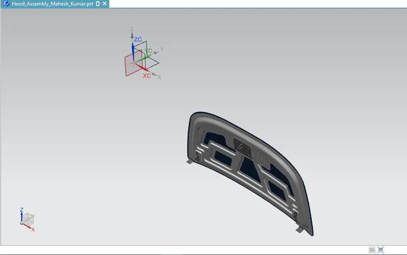
fig 2.7: isometric view of the hood assembly.
Conclusion:
So, using the provided A Class surface and master sections as well as a thorough understanding of the design criteria to be taken into account for the hood design, the car hood is created.