Wiring harness design in CATIA V5 - 3D modeling Week 7 Challenge
First of all I have open the Assembly which is done in week 4 challange.
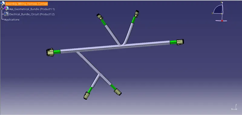
Now for creating flatting product file I am going to create file-->new-->product file and click ok.
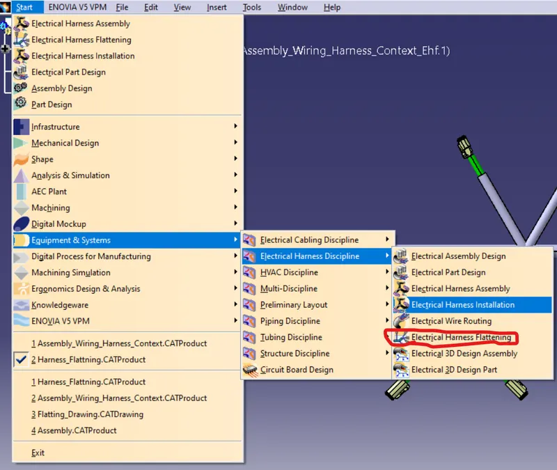
new productfile window is open. Now I have to go to the flatting workbench for that go to the start-->Equipment & System--> Electrical harness displine --> Electrical harness flatting click on it and the flatting workbench is opened.
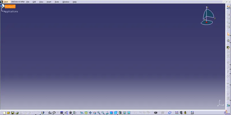
Flatting workbench is open as per below image.
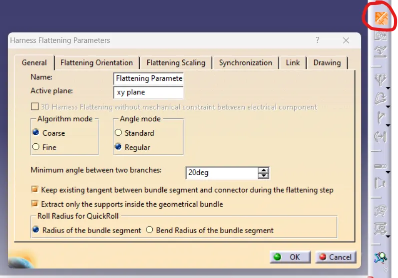
Now click on the icon of the "harness flattening parameters" which is used to define the all parameter for the flattening of the harness. Now I am inputting the all paramtere as per below images.
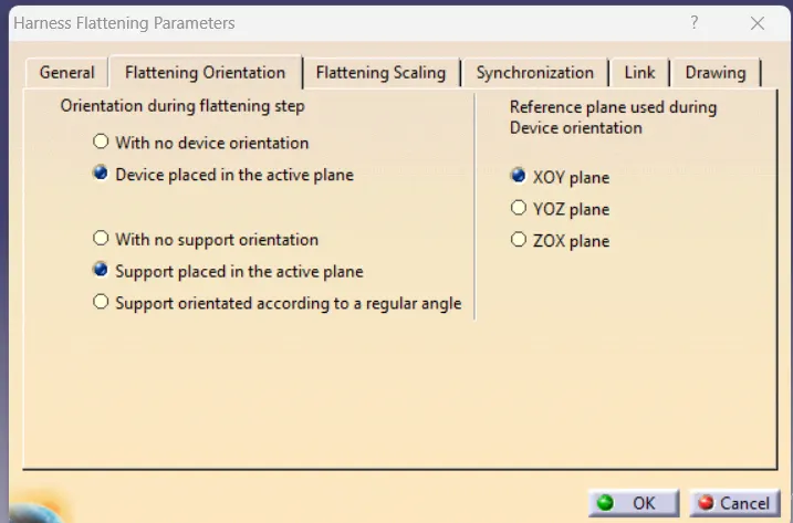
In the Flattening Orientation I am selecting parameters as per below image.
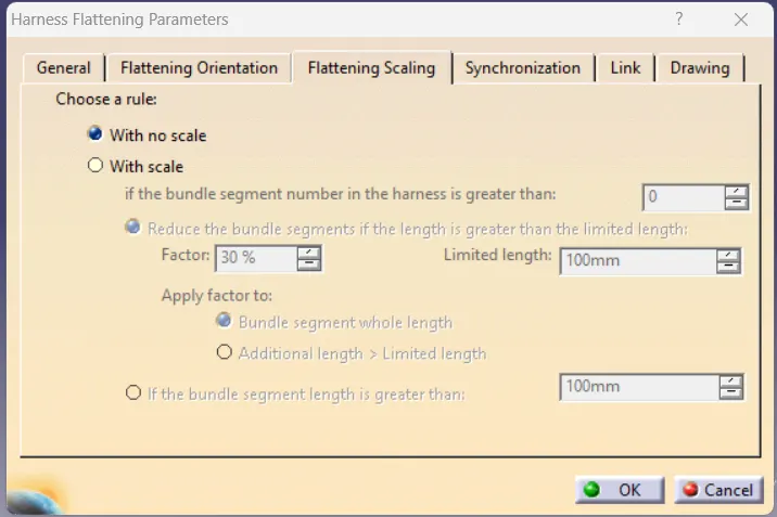
In the Flattening Scalling we can use the scale option for big harness assembly. I have choose the option as per below image.
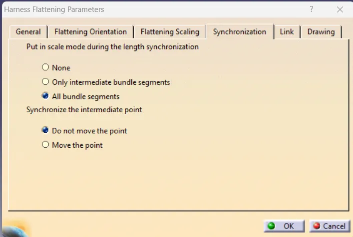
In the Synchoronization I am selectiong options as per below image.
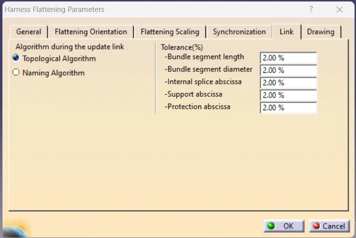
In the Link all parameters put as by default I am not changing any parameter and go ahed.
In the Drawing option I am selecting Single line for bundle segment and Double line for protective covering and other all parameter selecting as per below image. and click on OK button.
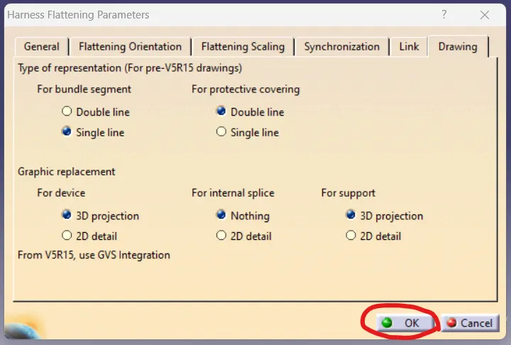
When I am click on OK button Flatting Parameter is added in the tree structure, So I can change it by using double click on that when required.

Now Open the Week 4 harness asssembly and I am set the both file in vertically so I can see it properly. Now I am click on "Extrct" icon as per below image and the go to the assembly and select the assembly from the tree structure.
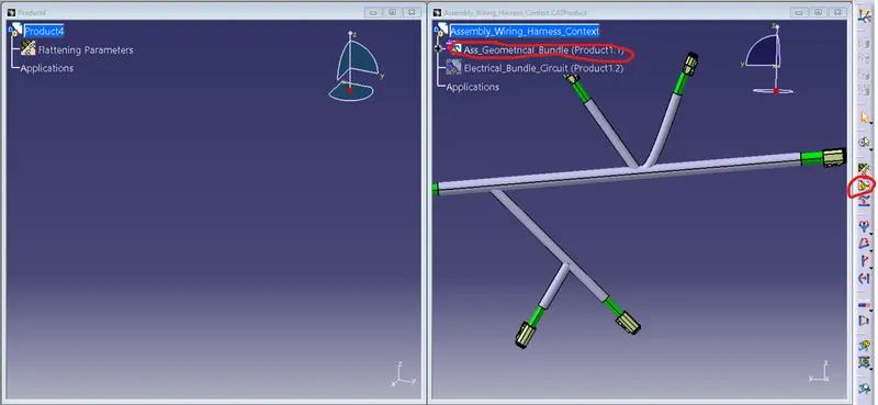
When I am selecting the assembly from the tree structure, the assembly file is closed and the assembly is added in the flatting product assembly and the extension is changed to Ehf file. After that click on update button so the file is properly updated.
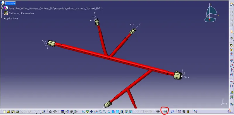
In the below figure we can see the updated file and also we can see the assembly file name changed and extension is chaged to Ehf .
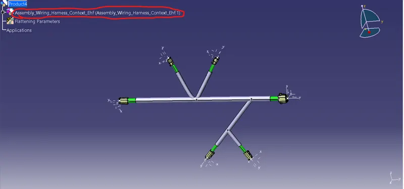
Now for flatting the above wiring harness click on the "flatten" icon and the dialouge box is open. In this dialouge box in the Active plane select the face of the one connector and then selecting the bundle which I want to flatten. So I am selecting one bundle and then click on the option of the select all branches.
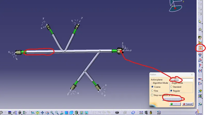
After click on the option select all Branches Click on OK button as per below image.
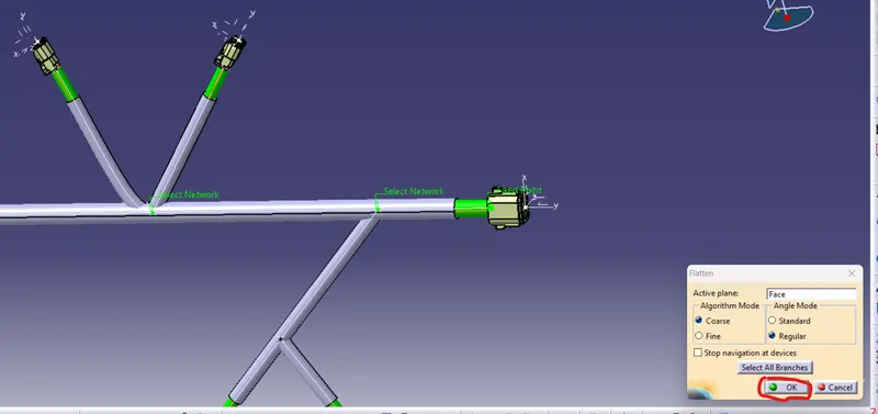
When click on ok button the all wiring harness assmbly is become flatten and click on update so the all assembly is updated.
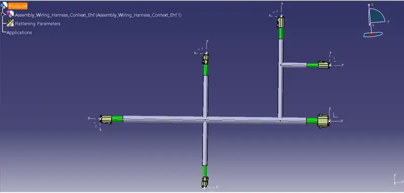
After Flatting the assembly I am reaaranging the branch as per required direction and location so I am using the different command in the flatting workbench. I am use the rotate command which is shown in the below image. click on the icon of the rotate command and the dialouge box is open as per below image. here we can give the angle as per requirement.
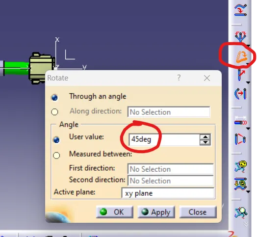
Now i am go to the option Alonge direction and select the main branch as direction. and then go to the option througe as angle.
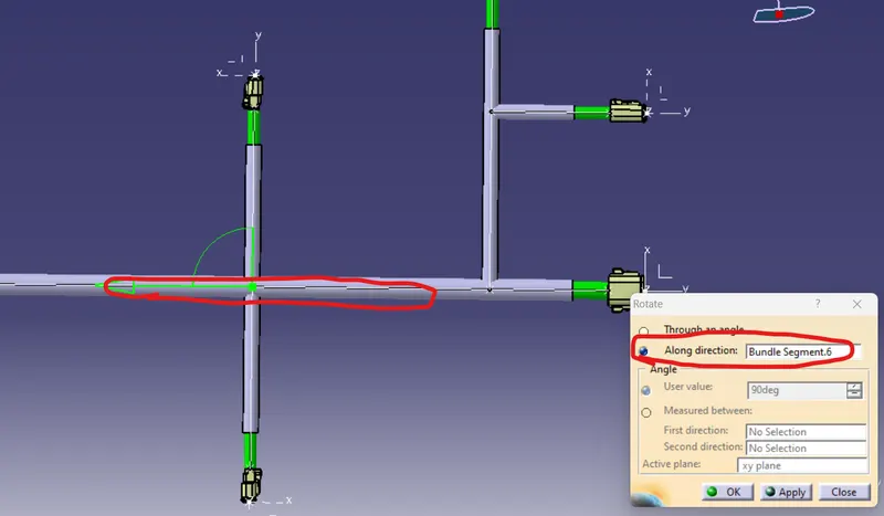
And in the through an angle giving the angle value and then click on ok button.
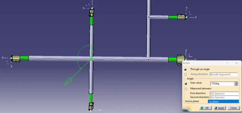
when click on ok button the branch is rotate and after that click on update button so the result is update properly.
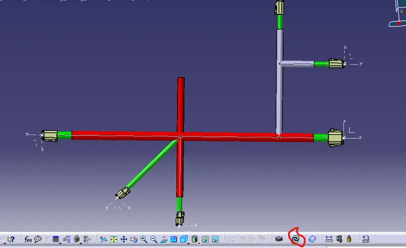
when click on update button the harness is upadted as per below image.
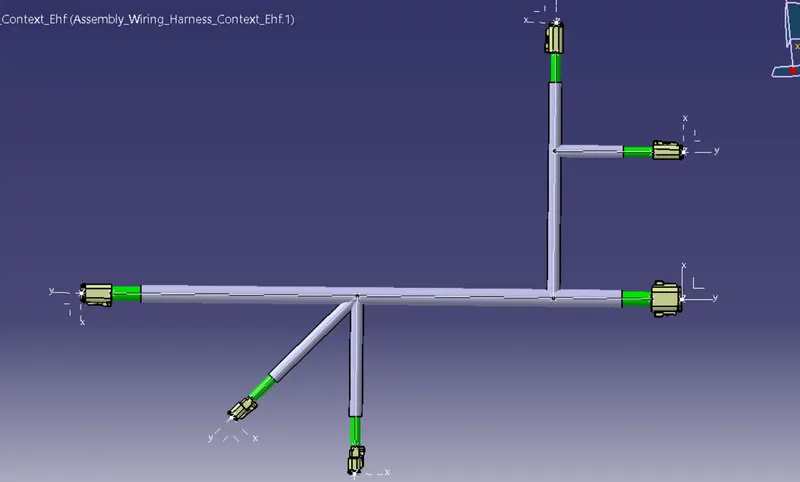
By following above steps I am rotateing all required branches and the final flatteing harness assembly is become as per below image.
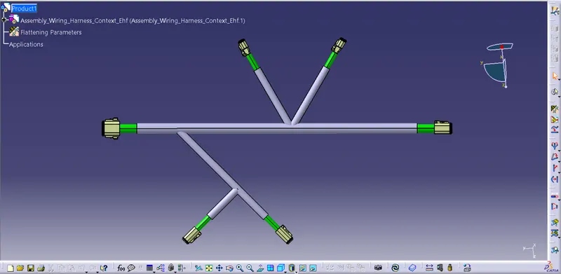
Creating Drawing file:
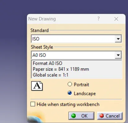
Now, for creating drawing file of the flatting assembly I am click on the File-->New-->Drawing file and the dialouge box is open as per below image. In this dialouge box I am selecting the standard as ISO and sheet style as A0 and ladscape formate. And click on ok button.
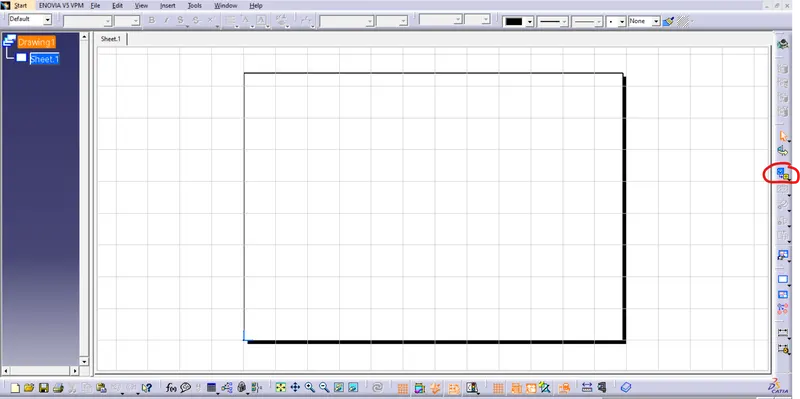
When click oK the drawing sheet is open as per below image here in this drawing sheet we have to add the different views for the product but here I have wiring assembly product so , I need to add only front view of the product. So, click on the front view icon shown in below imgae.
I am set the verticle view so the both file is visible properly. Here when click on the front view I have to select the plane for the front view so i am go to the flattening assmbly and select the connector face as front view and when i am selecting the face the front view of the harness assmbly is added in the drawing sheet.
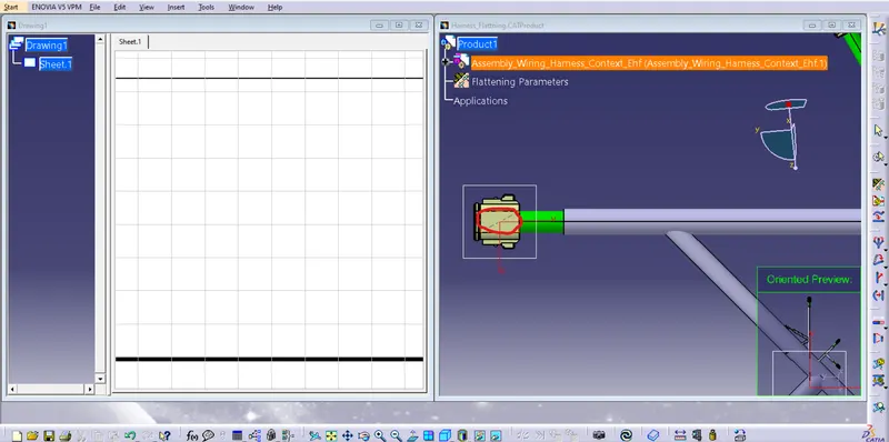
The front view is added as per below image here we can rotate the view as per our requirement by using the option given in the right side top corner.
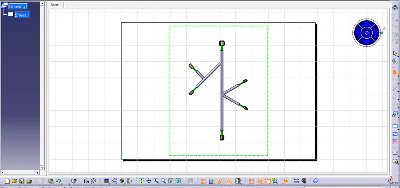
I am rotating the view by using the icon given in the right side top corner shown in below image.
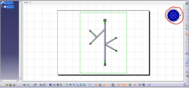
When the desired direction is set i am selecting the mouse corser in the blank side of the sheet so the view is added and updatded accordingly. Shown in below image.
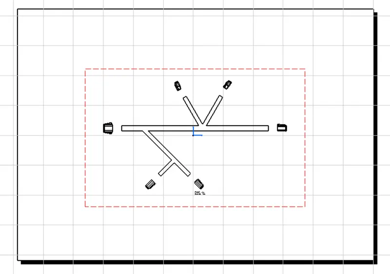
Now In the drawing the branches is not properly visible. So Select the Front view and right click and go to the option properties. the dialouge box is open as per below image. In the properties select the view and in the Dressup features select the 3D Wireframe and in the option select the Is always visible and click on apply and than click on OK button.
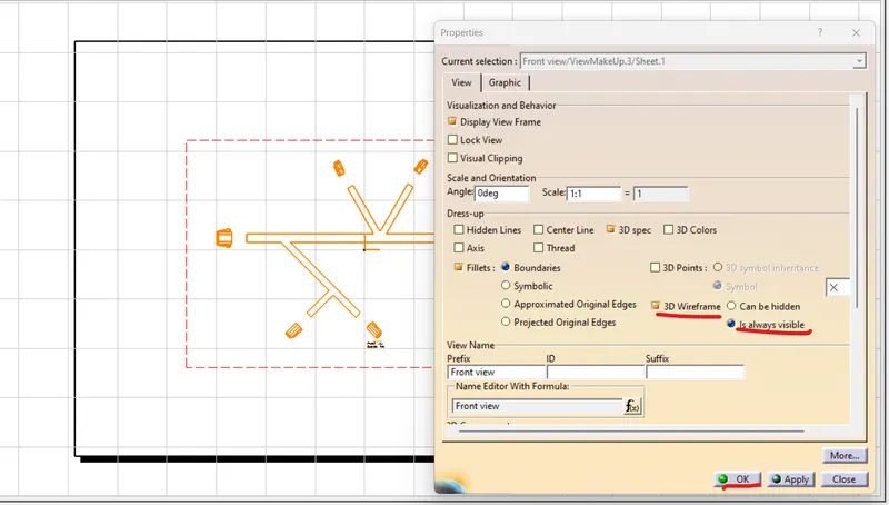
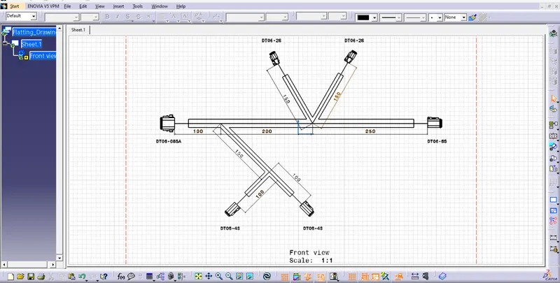
When click on OK button the wireframe view is visible and the front view is visible as per below image. And then I am providing the Distance for the Drawing by using smart dimension.
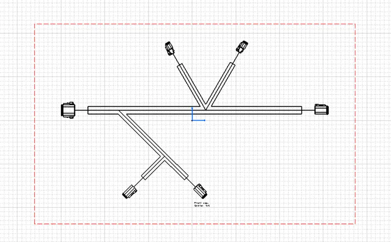
After providing all details of the drawing, the drawing is looks like below image.
I am attached both files Week 4 and Week 7 zipfiles . In week4 file the assembly file which is used as a reference which I am going to flatten. and in week 7 the flattening file and the drawing file is added.