Week -2
Link for Simulink model of Doorbell using solenoid block
https://drive.google.com/file/d/1NCWyl8-x-EuBNr9QReVB-tRKjAwDs3lF/view?usp=sharing
Link for Simulink model of thermistor to sense the temperature of a heater & turn on or turn off the fan
https://drive.google.com/file/d/17rKjZUtSTRUl-b3kebZlqC40Yq0v7d_G/view?usp=sharing
1)Simulink model of Doorbell using solenoid block
Solenoid is the generic term for a coil of wire used as an electromagnet. It also refers to any device that converts electrical energy to mechanical energy using a solenoid. The device creates a magnetic field from electric current and uses the magnetic field to create linear motion, and hence it causes the hammer to strike the gong at regular intervals.
The Block Diagram for the Solenoid is given in below:
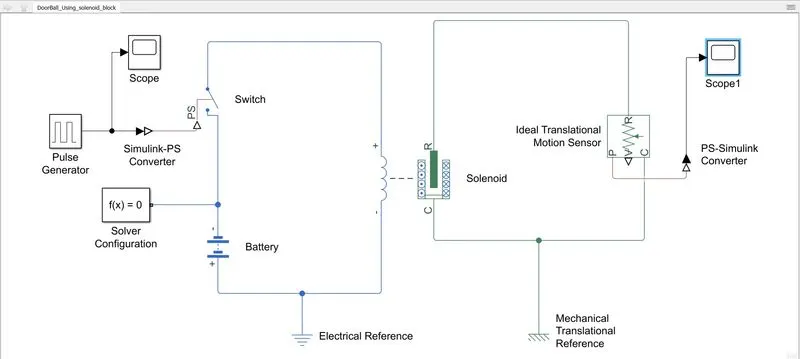
Here in this block diagram I have used pulse generator for input which is create the square waves pulses at regular intervals.
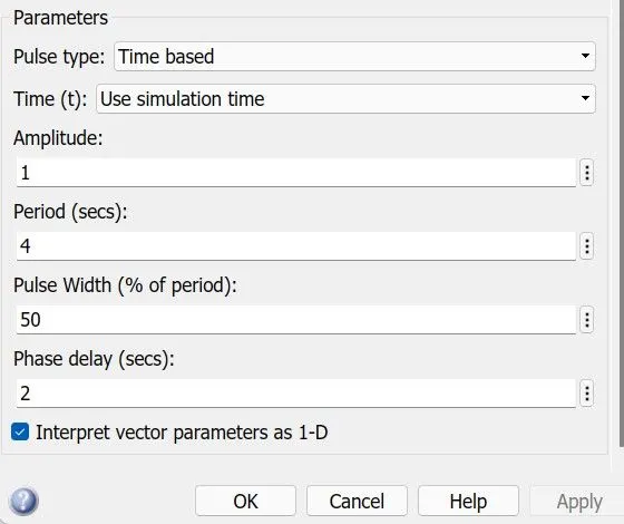
The block waveform parameters Amplitude,pulse width,period and phase delay,determine the shape of the output waveform.
I have provide the input in pulse generator as below:
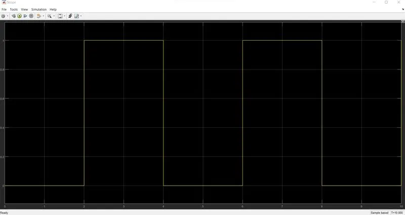
and the scope of this input pulse is as below:here the cycle is repeat for 10sec
The switch block used is controlled by external physical signal(pulse generator). If the external signal is greater than the thresold parameter then the switch is closed, otherwise switch is open. here in the parameter the thresold value of the switch is taken as 0.5. The positive terminal of the solenoid is connected to switch and the negative terminal is connected to the electrical reference. The port c is connected with mechanical reference. The ideal translational motion sensor is connected with solenoid block R to observe the movement of the plunger. Scope is connected with the ideal translational motion sensor to get the output. PS-Simulink converter is used to convert the physical signal to simulink signal. Solver Configuration:Each physical network represented by a connected simscape blocks requires solver setting information for simulation.
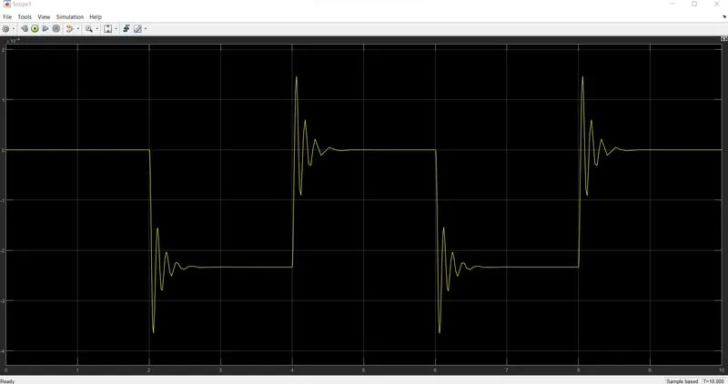
Now when i am going to run this simulink model for 10sec i get the output scope is below:
2)Use a thermistor to sense the temperature of a heater & turn on or turn off the fan as per the below conditions:
Temperature source: 20 °C from 0 to 10 seconds, 27 °C from 10 to 30 seconds, 23 °C from 30 to 50 seconds
Fan conditions: ON if the temperature above 25 °C, OFF otherwise.
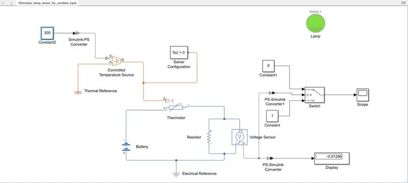
For the above given condition i have create a block diagram for the thermistor in which first i am using constant input block and check for the value of voltage at 298K temperature. and i am going to put that value at the switch condition as a thresold value. i have put the condition if the value of voltage is greater than the thresold voltage then the lamp is show the red color, and if the voltage is greater than the thresold voltage the lamp is show the green color. because the switch can not measure the temperature sense. so using the thermistor diagram with the voltage sensor it sense the temperature and show the voltage value which is used in switch. So, after that checking the condition using the constant input. i have create the block diagram with the repeating sequence stair in the model.
where i have input the signal value as given below.
In the block parameter of the repeating sequence stair i have put the input [293 300 300 296 296] and the sample time is taken as 10sec. and going to run the whole simulation for 50sec. here i have put the all values of temperature in kelvin.
Block Diagram for the Thermistor sensor is given below.:
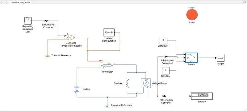
The Output is show the red color in the lamp because at 50sec the input value for temperature is 296 which is less than 298 so the fan is not going to run.
the scope plot of the above block diagram is as below:
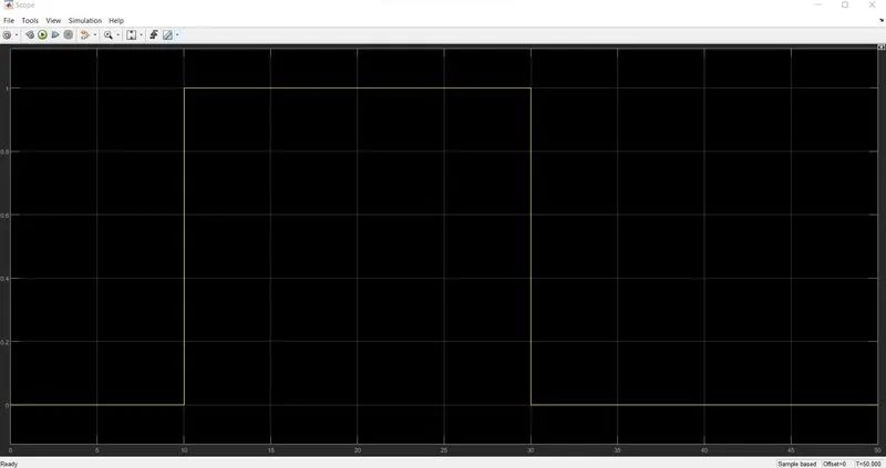
in the above plot we can see the voltage sensor output for 50sec in which the output show the 0 for 10 sec in which the input is 293K and then for next 10sec to 30sec it shows the output as 1 in which the input is given 300k. then for next 30sec to 50sec the output shows the value 0 because of the input is 296K.
Now i am showing the block diagram for constant value for 293K in below Fig in which the output show the red lamp because it is below 298K so, the fan is not working.
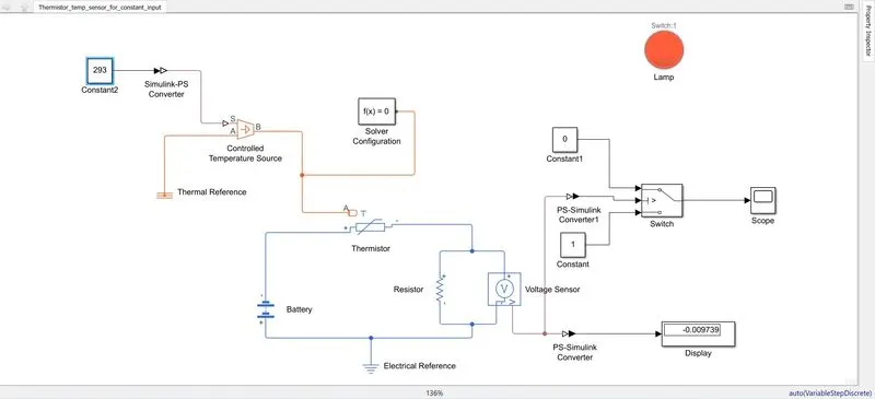
and same as i am showing the block diagram for constant value for 300K in below Fig in which the output show the green lamp because it is above 298K so, the fan is working.