Section Modulus calculation and optimization
Objective:
Use the Section of Hood design and calculate the section modulus using the formula S = I/y
S = Section Modulus
I = Moment of Inertia
Y = distance between the neutral axis and the extreme end of the object
Create a new section that has improved the section modulus of the previous section.
Section modulus:
What is Section Modulus:
Section modulus is a geometric property for a given cross-section used in the design of beams or flexural members. Other geometric properties used in design include area for tension, radius of gyration for compression, and moment of inertia for stiffness. Any relationship between these properties is highly dependent on the shape in question.
Types of Section Modulus:
There are two types of section moduli,:
1) The elastic section modulus (S), and
2) The plastic section modulus (Z).
1) Elastic Section Modulus:
For general design, the elastic section modulus is used, applying up to the yield point for most metals and other common materials.
The elastic section modulus is defined as,
S = I / y,
Where, I is the second moment of area (or moment of inertia), and
y is the distance from the neutral axis to any given fiber.
It is often reported using y = c, where c is the distance from the neutral axis to the most extreme fiber , as seen in the table below. It is also often used to determine the yield moment (My) such that,
My = S × σy
Where, σy is the yield strength of the material.
Equations for the section moduli of common shapes are given below.


 ,
,





2) Plastic Section Modulus (PNA):
The Plastic section modulus is used for materials where (irreversible) plastic behavior is dominant. The majority of designs do not intentionally encounter this behavior. The plastic section modulus depends on the location of the plastic neutral axis (PNA). The PNA is defined as the axis that splits the cross section such that the compression force from the area in compression equals the tension force from the area in tension.
So, for sections with constant yielding stress, the area above and below the PNA will be equal, but for composite sections, this is not necessarily the case. The plastic section modulus is then the sum of the areas of the cross section on each side of the PNA (which may or may not be equal).


 ,
, 


 =width,
  =thickness,
  are the distances from the neutral axis to the centroids of the flanges respectively.



The plastic section modulus is used to calculate the plastic moment, Mp, or full capacity of a cross-section. The two terms are related by the yield strength of the material in question, Fy, by Mp = Fy ⋅ Z. Plastic section modulus and elastic section modulus are related by a shape factor which can be denoted by k, used for an indication of capacity beyond elastic limit of material. This could be shown mathematically with the formula :-

Shape factor for a rectangular section is 1.5.
Significance Of Section Modulus:
- Section modulus is the important factor for design of beam and flexural member design.
- As Increase the section modulus, resistant to bending of the beam is increase.
- It is easier to calculate stresses in beam and an exact measure of strength of steel.
- Section modulus is directly proportional to moment of innertia. So Increasing the value of innertiea we needs to increase the value of section modulus. And increasing of section modulus will be making the components tougher and more capable to withstand larger loads.
Calculations For Section Modulus of Hood:
Initial Hood design and it's moment of inertia:
Here, for calculating the moment of inertia I have opened the Hood Assembly and hide the other all part except the inner panel and outer panel of the hood. Then taken the cross section of this two parts and after that i have take the sketch on the datum plan and joined the inner panel outer line and outer panel outer line. Then using section analysis in that i have select the sketch and i have found the minimum moment of inertia of this section is 1.044253490e+05.
Iox = 1.044253490e+05 = 104425 mm4,
Y = 486.62 mm,
S = I/Y = 104425 mm4 /486.62 mm = 214.59 mm3
Here, I is “moment of inertia” and y is distance from “neutral axis” to top or bottom of fiber.
Yield moment My = S × σy,
where σy is the yield strength of the material which is 520 MPa or N/mm2.
M = S × σy = 214.59 mm3 x 520 N/mm2 = 1,11,588.097 N mm = 1.11e+05 N mm.
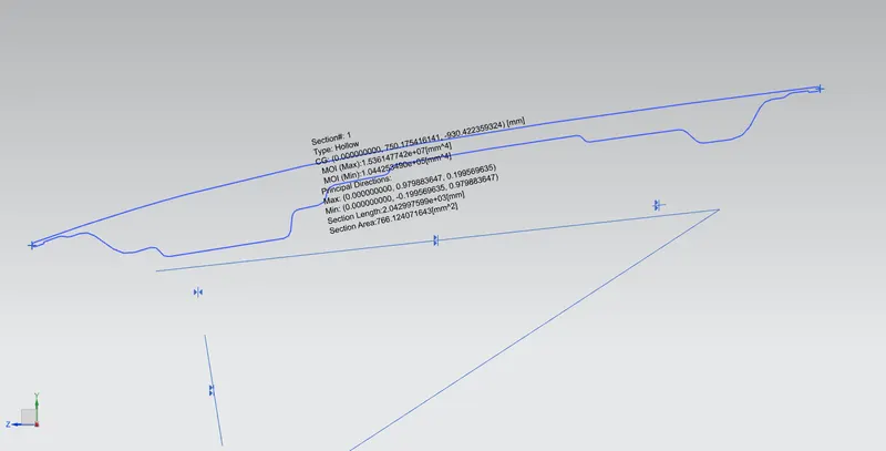
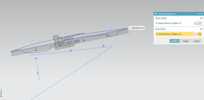
To increase the strength of the above section, I increased 0.2mm the distance between the outer panel geometry to inner panel geometry and also modifying the emboss design and then repeated the above same procedures then we have got much better strength value. See below section 2 calculation part and images.
Modified section of hood:
Increasing the inner pannel distance from outer panel by 0.2mm and also modifying the emboss design.
Iox = 1.234691988e+05 = 123469 mm4,
Y = 486.84 mm,
S = I/Y = 123469 mm4 /486.84 mm = 253.61 mm3
Here, I is “moment of inertia” and y is distance from “neutral axis” to top or bottom of fiber.
Yield moment My = S × σy,
where σy is the yield strength of the material which is 520 MPa or N/mm2.
M = S × σy = 253.61 mm3 x 520 N/mm2 = 1,31,878.810 N mm = 1.31e+05 N mm.
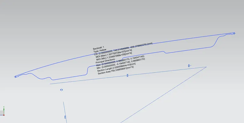
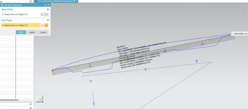
Conclusion:
Here, we can say that if we increase the area of cross section we can increase the moment of ineria value as vell as strength value of that section. I have increase the distace by 0.2mm in between the inner panel and outer panel and also modifying some embose and after that analysing the section I have get the value is higher. And strength of the section is increased as well.
I have attached my model with the name of as below:
Original Hood Section name: "Hood_Assembly"
After Modification section name: "Hood_Assembly_Modified_Section"
Reference:
https://en.wikipedia.org/wiki/Section_modulus
https://www.engineersedge.com/material_science/section_modulus_12893.htm