Week 9 - Project 1 - Door Trim Lower with Engineering Features
Objective:
The main aim of this challenge is to create a solid body of 'Door Trim Lower' including heat stakes and locators with the help of the closed surface method by using the 'Generative shape design' workbench in CATIA V5. also Performing the 'Draft Analysis' on the solid part body of the Door trim.
TOOLING AXIS:
To create the tooling axis, I extracted a surface from class A and created a point in the middle of the surface by using the point command. after that taking intersection of the surface from the point and extracting the two intersection line and using those two lines i have create a bisecting line passing from the point which is called as a Tooling Axis.
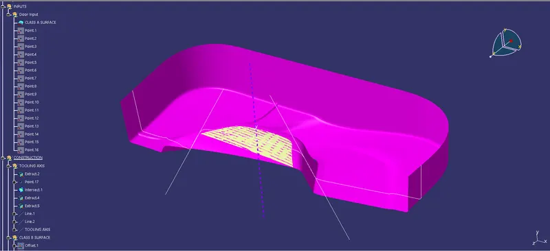
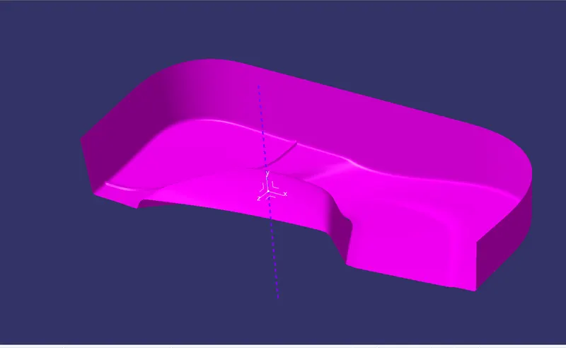
DRAFT ANALYSIS FOR CLASS A SURFACE:
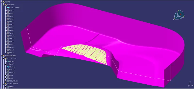
We do perform the draft analysis to check for class A surface before we make solid and creation of B-side features. for draft analysis first we need to change to the material mode. Initially I align the compass to the tooling axis and I gave a 3deg draft angle. and now the surface is highlighted in green colour the draft angle is given properly for class A surface.
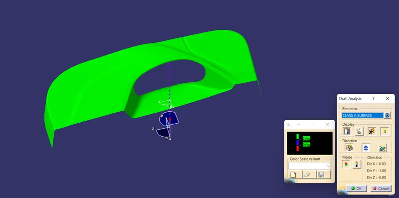
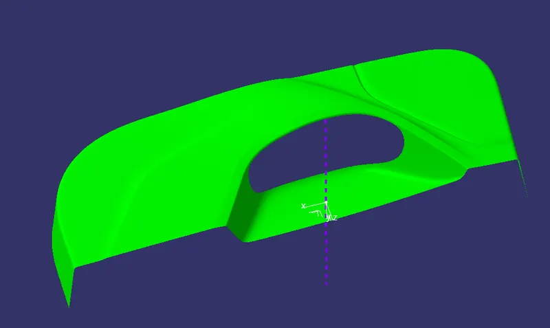
CLASS B SURFACE:
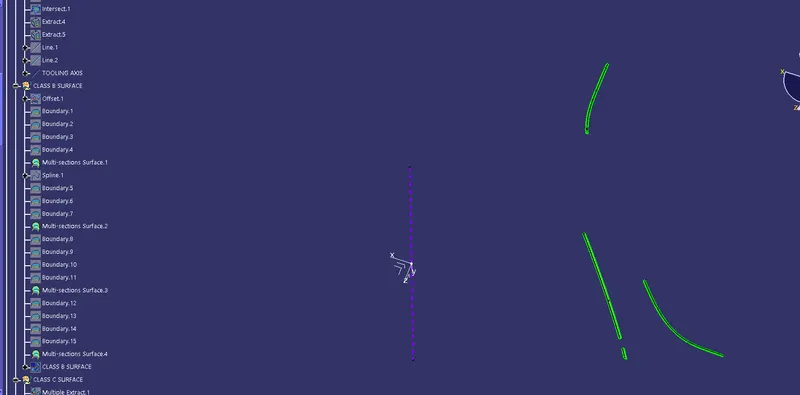
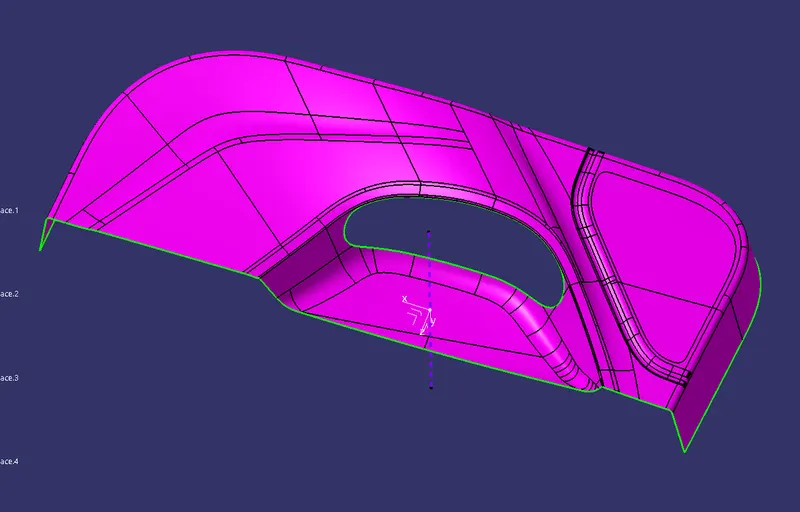
To create the class B surface, offset the class A surface inside 2.5mm. Once the offset is created, we can observe some patches on the offset surface by taking the boundary for the offset surface, those patches are formed due to the fillets on the class A surface. We need to cover those patches with the help of the multi-section surfaces command by extracting the patch boundaries. Once all the patches on the offset are covered properly join all the patches with the offset surface, to get the class B surface.
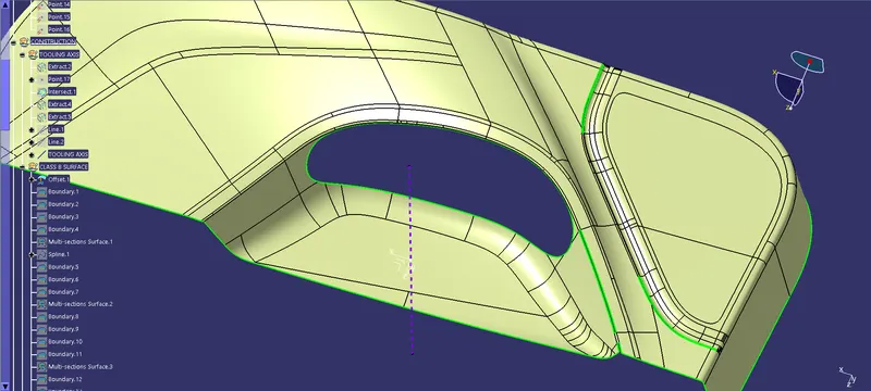
Class B surface as below:
CLASS C SURFACE:
To create a class C surface first I have use the boundry command on the class A surface. After that I have extracted the boundry of the class A surface and then sweep it with the tangent of the surface or draft angle to the tooling axis. After all sweep created I have joined all sweep to make the classs C surface. Here, there are two class C surface is created first one is the outer boundry of the class A surface and the second one is at the holeboundry in the middle of the surface.
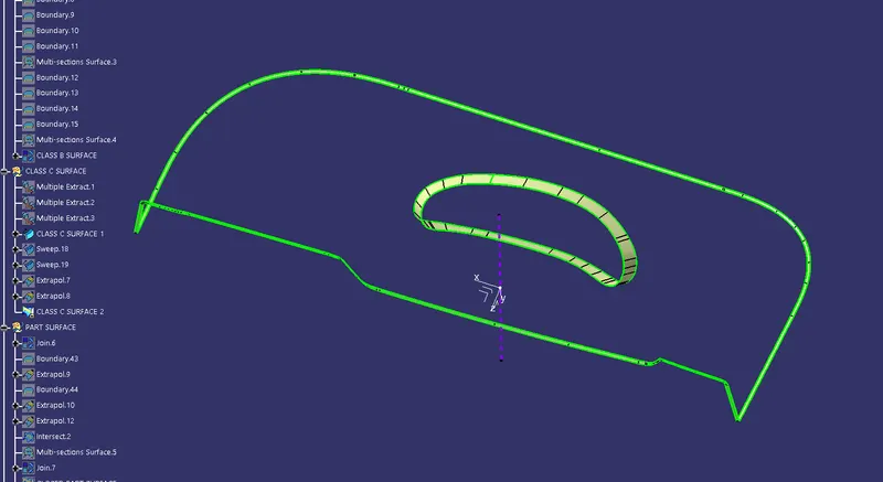
CLOSED SURFACE of the PART:
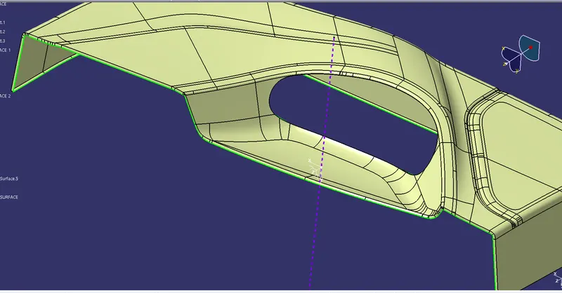
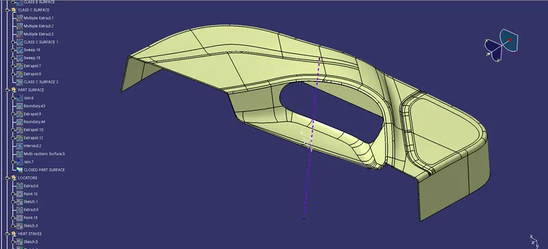
For creating the closed surface of the part first we need to join the class A surface to the class C surface. After that We extrapolate the class B surface so we can trim it. Now using trim command the trim the surface between the class B surface and the join of the class A and class C surface. And finally we got the closed surface of the given part.
join of the class A and class C :
closed surface of part:
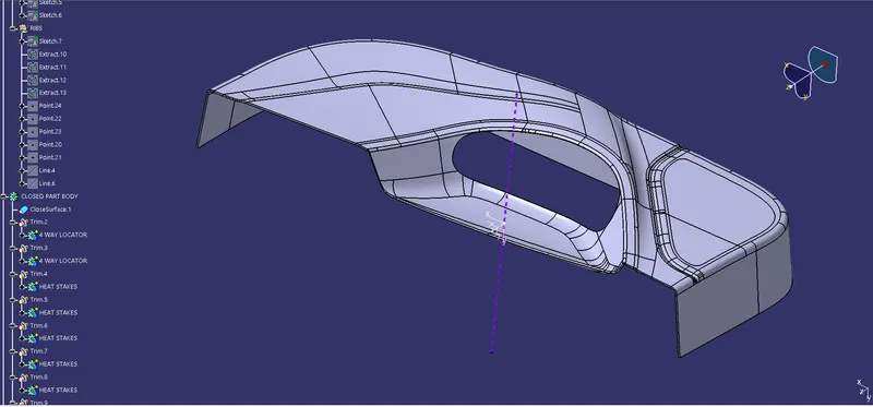
PART BODY:
To create the solid part body from the closed surface, I used the closed surface command in the part workbench.And select the closed surface which i wont to convert the part body.
CREATION OF LOCATORS:
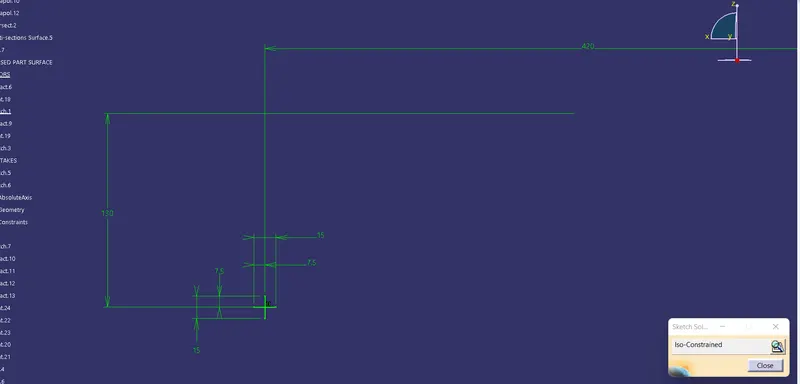
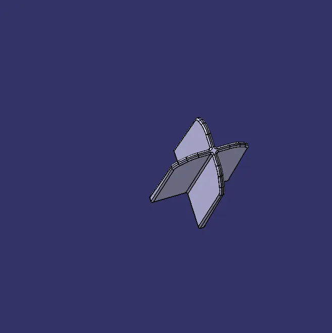
To create the locators, I created a sketch on the body. After creating the sketch, I pad it 20mm in height and thicken it to 1.3mm and I drafted it with 0.5deg in the direction of the tooling axis. I gave 3mm of chamfer with 45deg of inclination and after I gave a fillet of 0.25mm radius.
4-way locator:
CREATION OF HEAT STAKES:
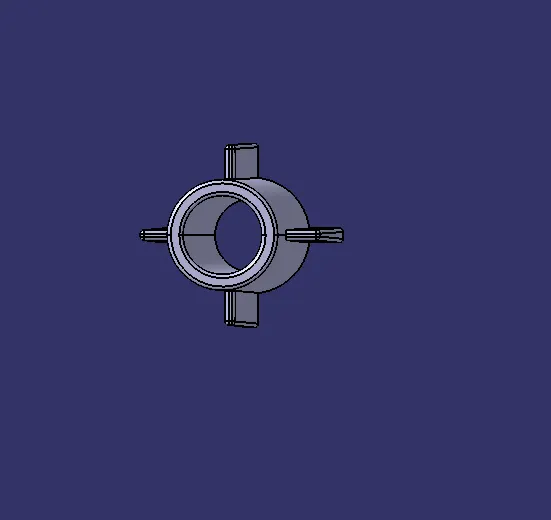
To create the heat stakes, I draw a sketch on the surface. After the creation of the sketch, I pad it to 18mm height and I gave a draft angle of 0.5deg on both sides (inside and outside) and then I gave a fillet with a 0.25mm radius. After creating the heat stake, I created the ribs for supporting purposes. To create the ribs, I draw a sketch and padded it to 12mm in height and 1mm in thickness. After padding the ribs, I drafted 0.5deg in the tooling asix direction and filleted it with a 0.25mm radius. Finally, I union trim the ribs with a heat stake to remove the ribs, which are present inside the heat stakes.
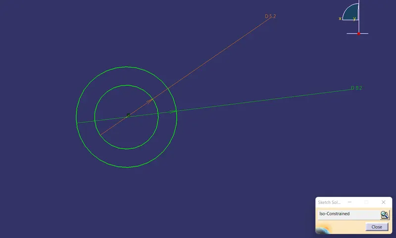
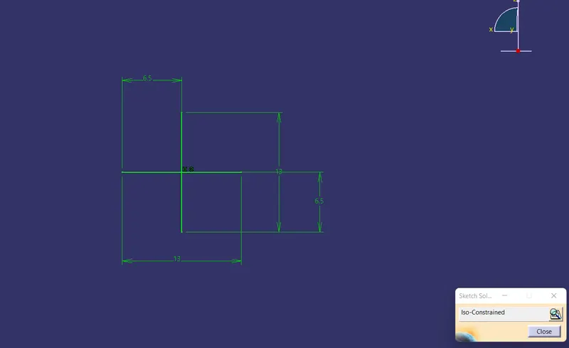
Heat stake with supporting ribs:
Now, I Copy the heat stakes and using paste special to the current window by link I have pasting the heat stakes and by using transpolation I move it to the desired position of point which are given in the input.
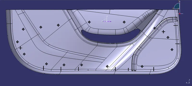
Final part body with 4-way locators including all the heat stakes with supporting ribs:
CREATION OF RIBS:
Ribs are a feature in plastic injection molded parts. They are thin extensions that run perpendicular from a wall or plane. They are commonly used to provide additional support and strength to a part. Thickness and location are essential to rib design.
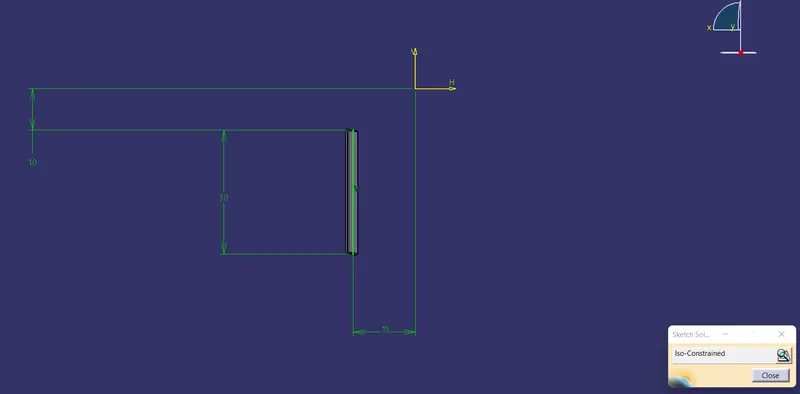
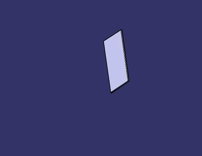
To create the ribs, I draw a sketch and padded it to 12mm in height and 1mm in thickness. After padding the ribs, I drafted 0.5deg in the tooling asix direction and filleted it with a 0.25mm radius.
DRAFT ANALYSIS FOR PART BODY:
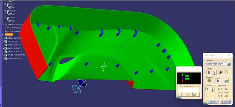
For the Draft analysis of the part body first we need to go to the material mode after that clicking on the draft analysis first I am inlining the axis to the tooling axis and lock it and after that in the color bar I gave the draft angle value first 3degree here i see that the ribs,heat stakes and the locators are in blue and other all portion is green, now i have give the value of the draft angle to the 0.48 and after that I have seen all the body to the green color..
FOR 3 DEGREE:
FOR 0.49 DEGREE:
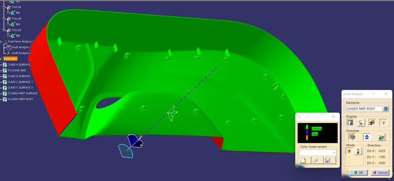
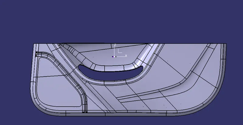
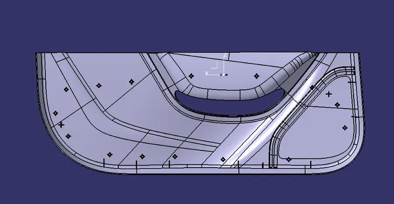
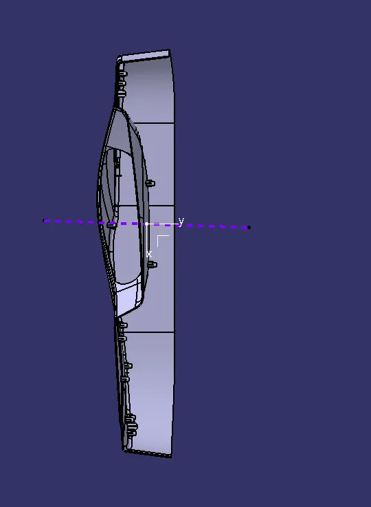
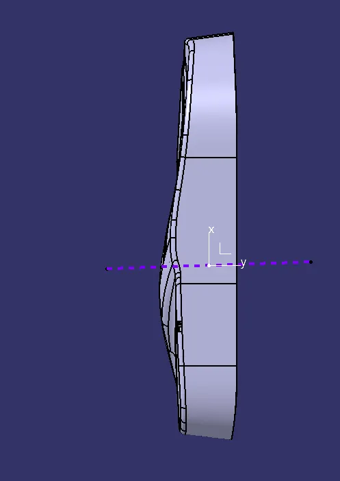
Screenshots of the completed design in various orientations:
ISO VIEW:
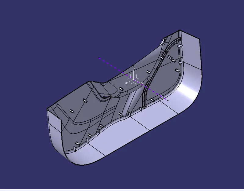
FRONT VIEW:
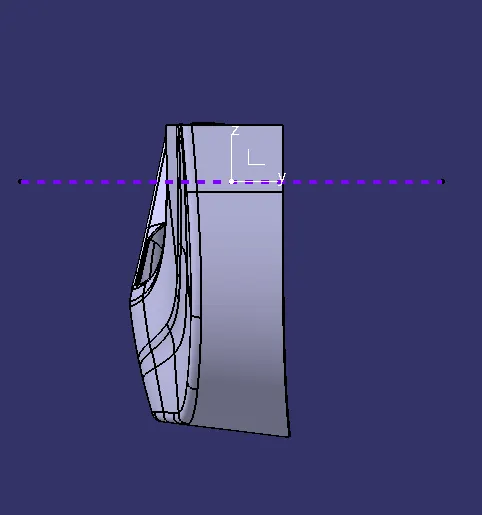
BACK VIEW:
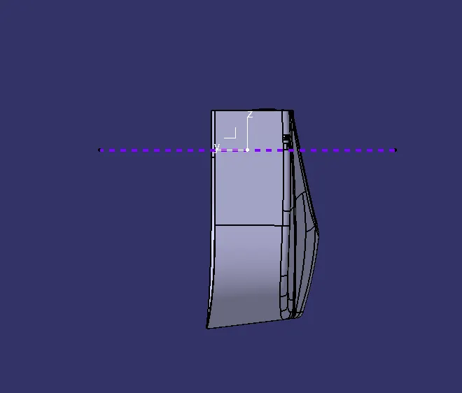
LEFT SIDE VIEW:
RIGHT SIDE VIEW:
TOP VIEW:
BOTTOM VIEW:
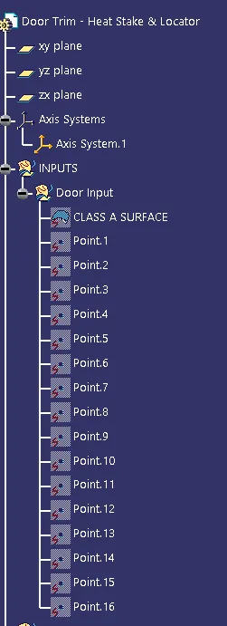
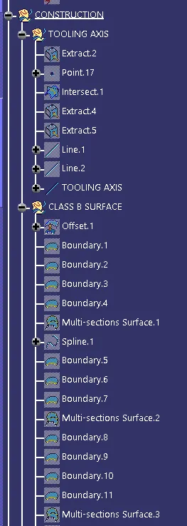
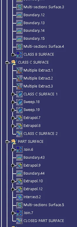
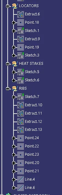
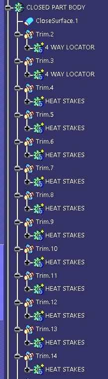
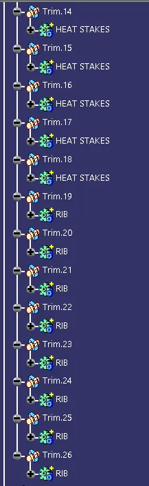
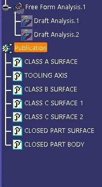
TREE STRUCTURE: