Week 8 - Challenge 6 - Core & Cavity Design
AIM : To Create the Core and Cavity blocks for the switch bezel designed in the earlier challenge.
The core is the part which forms the internal shape of molding. The cavity is the part which forms external shape of molding.Core is the side of the tool where the plastic part is injected from which is also known as the bottom half of the tool. The upper half of the mold is called as CORE.A tool with one impression is often called a single impression (cavity) mould. A mould with two or more cavities of the same parts is usually called a multiple impression (cavity) mould.
The outside of the enclosure will be a cavity in the A-side of the mold and the inside will be a core on the B-side.
Now, First we open the model which I have created in the previous Example. Opening the switch besel part model.
TOOLING AXIS:
First of all for creating the tooling axis, we use the bisecting lines method. for that First,we decide the proper tooling axis direction with respect to the given component. here, in this case it is the Z-axis direction.
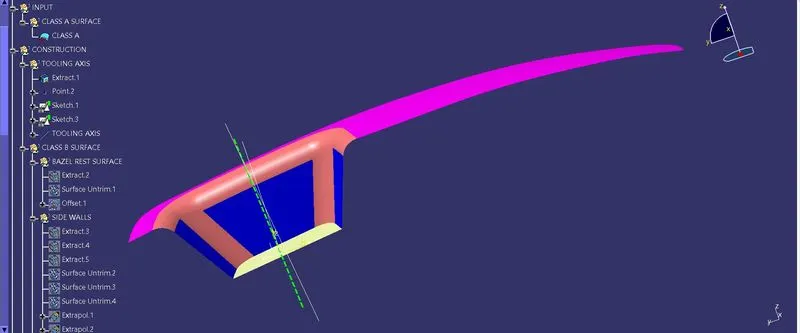
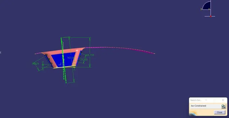
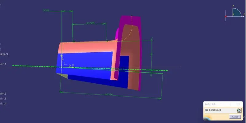
After that, we create a point and an axis system on the Class-A surface and then create two sketches on the zy and zx planes respectively. In the first sketch on the zy plane, we will draw two inclined lines coinciding with the intersection curve of the Class-A surface along the y-axis direction. and for the second sketch we take the manual line at the draft angle and Then we will create a bisecting line using these two lines.
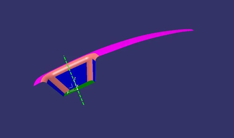
CLASS A SURFACE DRAFT ANALYSIS:
For performing the draft analysis of the class A surfface first of all put the axis to the incline of the tooling axis and lock the axis and then select the surface for analysis.
Now use the free point to see the different values of angles on the draft surface.
Here, in the below image I have shown the color code which I have used for draft analysis.
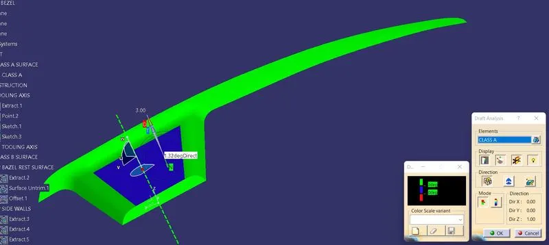
When done the analysis click on Ok button and we get the analysed surface as per below image.
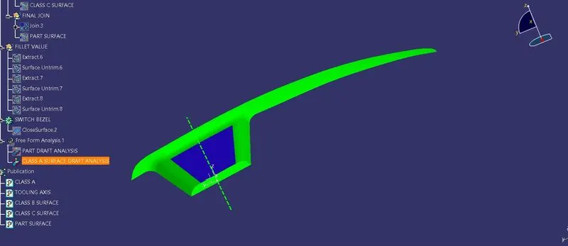
CLASS B SURFACE:
First, Extract the class A surface and then untri the surface after that Extrapolate the surface.
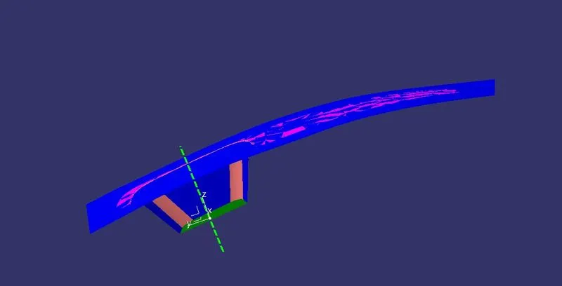
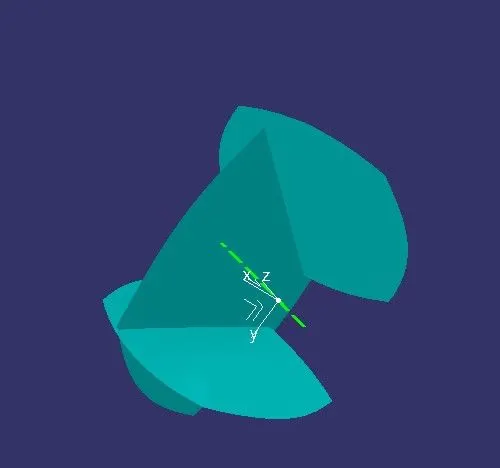
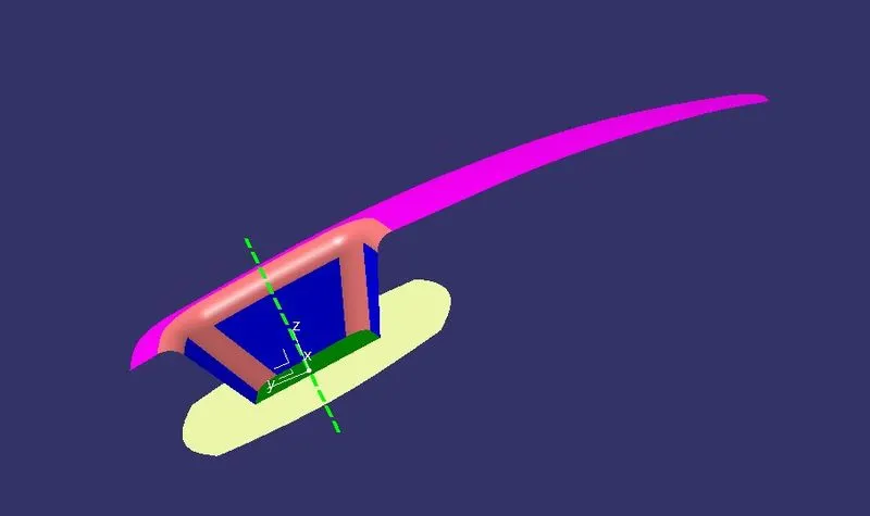
Here there are three surface bazel rest surface,side wall and base Surface. After Doing Extrapolation of all these three surface Trim the extra surface so we can get the class A surface which is Offset 2.5mm beacause the wall thickness is given ,and then we get the desired Class-B surface.
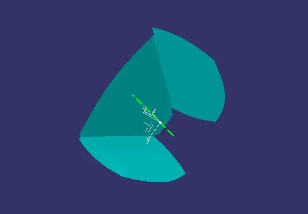
After that, we will use the Trim command to get out proper desired Class-B surface.
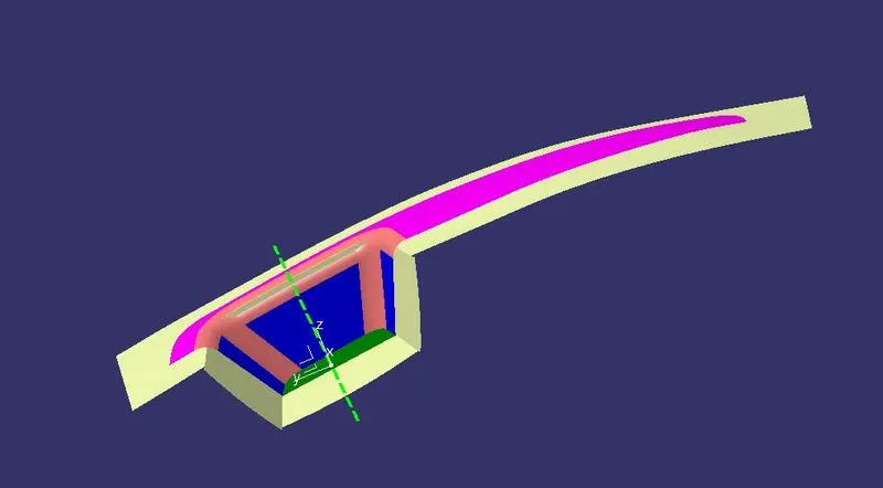
Now using the fillete command give proper fillets to the edges of the Class-B surface. Here before giving the value of edge radius measure the readius of the class A surface and according to that the radius value is given.
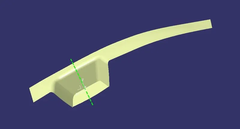
CLASS C SURFACE:
Here, we extract the outer edge boundary and inner edge boundary of the Class-A surface separately using multiple extract command.
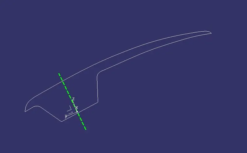
Then, Sweep each of these boundaries using the sweep command. and select the Line option on the sweep command menu,give the input as extracted boundaries as Guide curve 1 and the tooling axis as the draft direction and specify the draft angle as 3 degrees.
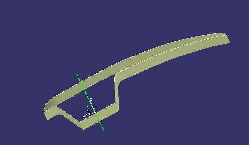
FINAL SURFACE:
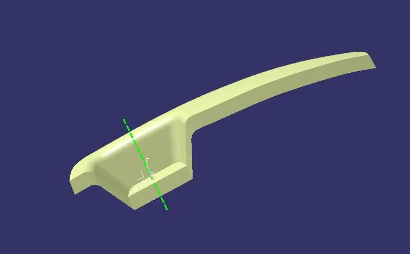
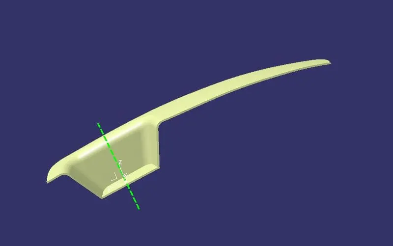
For creating the final part surface first join all the Class-C surfaces with the Class-A surface by using the Join command. and then use the trim command to join the Class A, B and C surfaces together and obtain the proper desired surface.
PART BODY:
For create the final solid body use the Closed Surface command. Go to Boundary command and click on the new surface. An error dialog-box should pop-up which mean the surface is closed. now, Go to the Part Design workbench. and Select the Closed Boundary option and then click on the generated surface.hear, we obtained closed solid body.
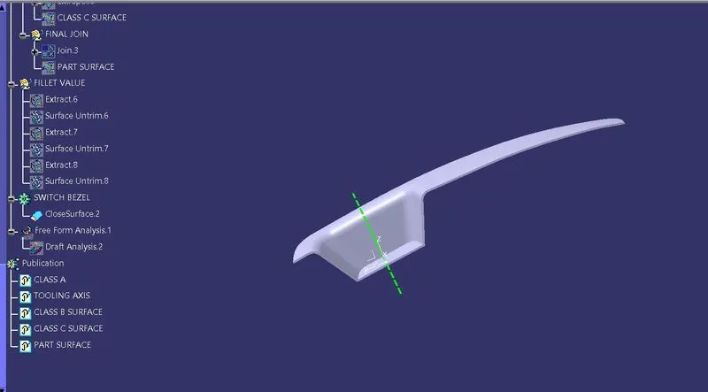
DRAFT ANALYSIS OF THE FINAL SOLID BODY:
Since, the draft analysis is not giving us the desired result we must modify the inclination of the tooling axis to increase its inclination angle and thus by some trial and errors we get our desired value.
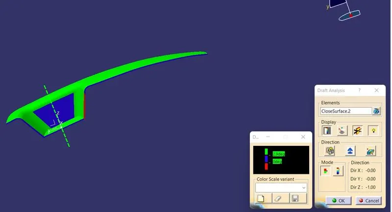
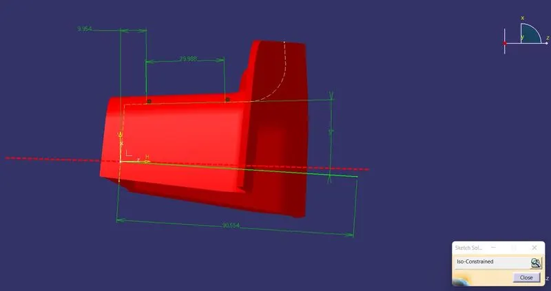
We change the inclination angle of zx plane line to 5 degrees.
We now, get our desired output.
DIFFERENT VIEWS OF DRAFT ANALYSIS OF SOLID MODEL.
ISO VIEW
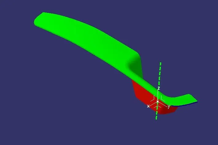
FRONT VIEW
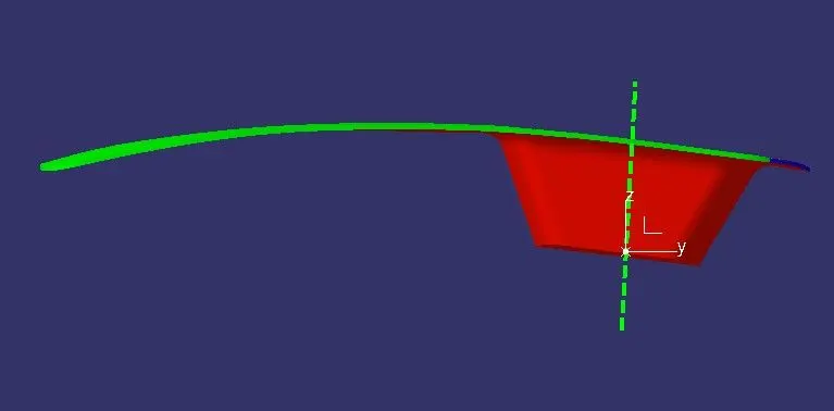
BACK VIEW
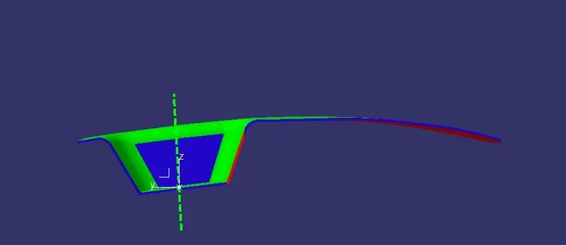
LEFT SIDE VIEW
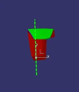
RIGHT SIDE VIEW
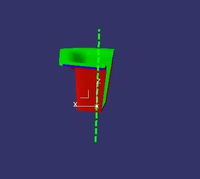
TOP VIEW
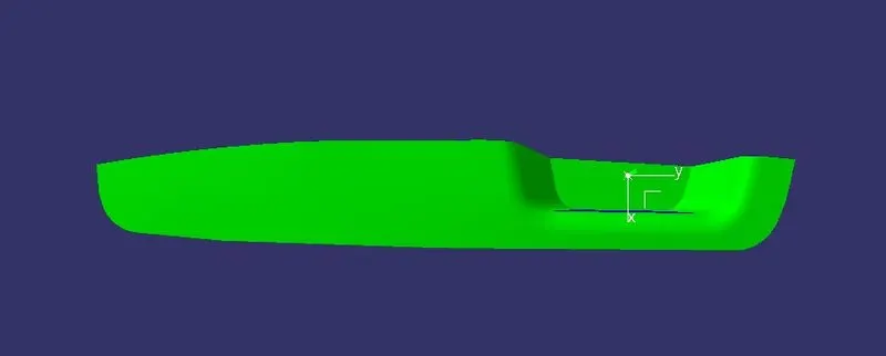
BOTTOM VIEW
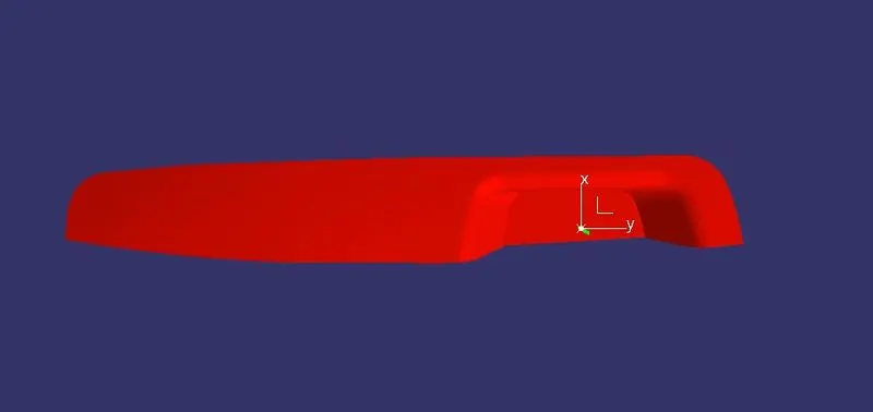
And for creating the core and cavity we required parting surface and parting line.
First, for creating parting surface:
Using boundry option take the boundry of the class A surface. and extrapolate the class A to 15.00mm.
And then trim it with the class C surface. and then trim it with the class B surface so we get the Parting surface with the component area.
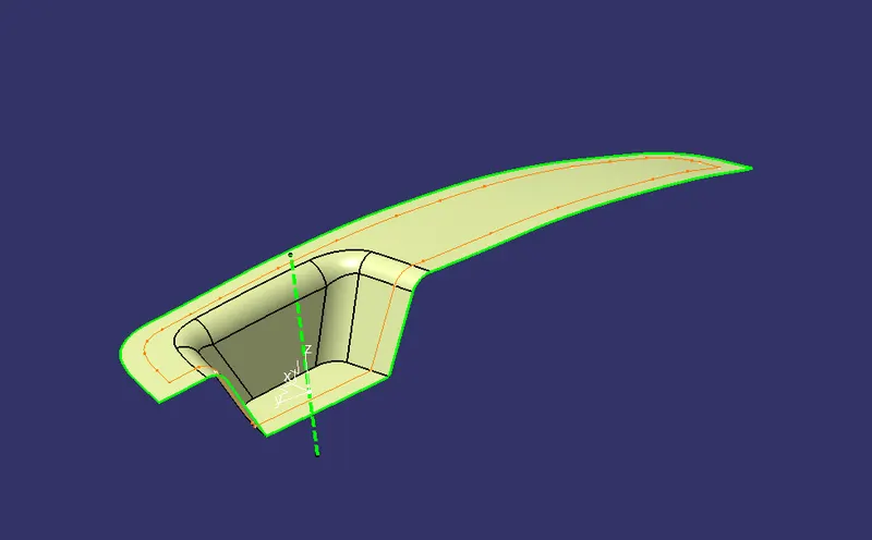
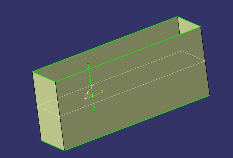
Now create sketch on the surface of the bottom side and create the rectangular boundry which cover the full class A surface. and extrude that sketch perpendicular to the part.
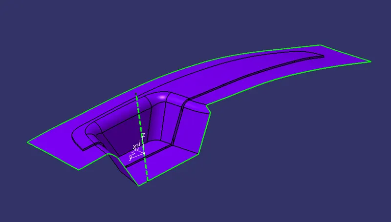
CAVITY :
For creating the cavity trim the extruded sketch to the parting surface with comopnent area so we get the outer surface for the cavity block, now for closing the surface creat boundry using boundry command and fill the surface . After that join both and we got the closed surface for cavity.

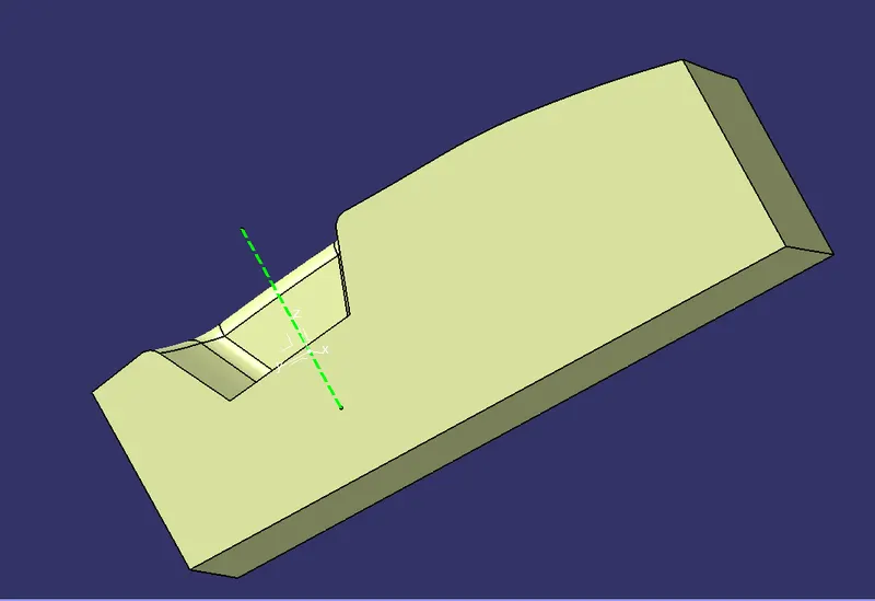
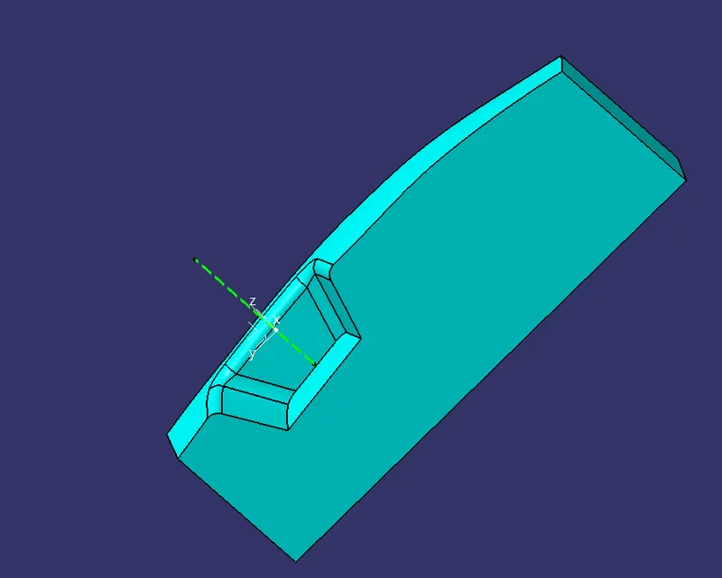
Nou go to the part workbench and using close surface we can create the solid part of the CAVITY.
CORE:
Same procedure for the core surface and getting the CORE solid part.
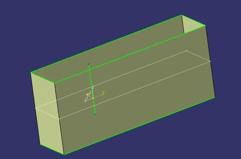
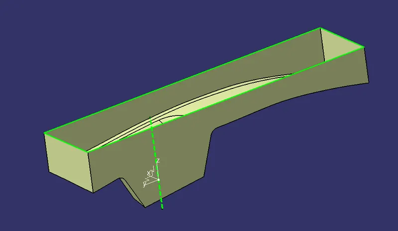
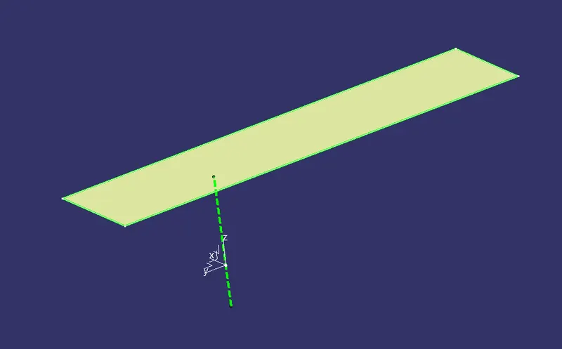
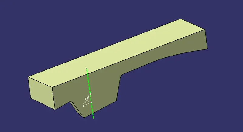
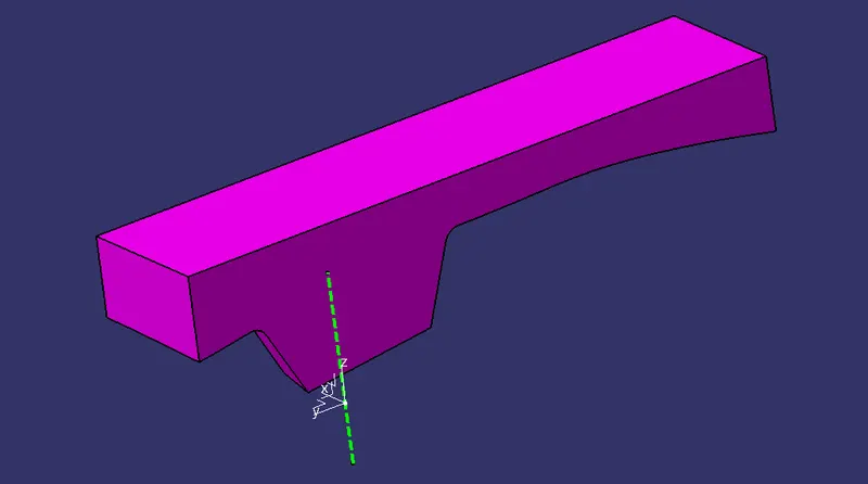
For seeing the acual process using intersection tool we intersecting the parting surface, core, cavity, and the part model. so we can see the actual progress either it is correct or not.
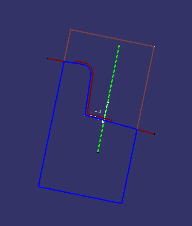
for creating the parting line we intersecting the join of class A and class C to the class B So, we get the parting line boundry.
Now using this parting line boundry we split the Parting surface with component are and so we get the actual parting surface.
Parting Line:
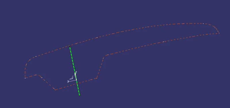
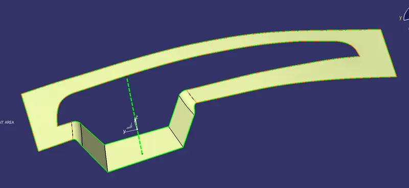
Now, In the below image i am uploading different views of core cavity combination:
ISO View:
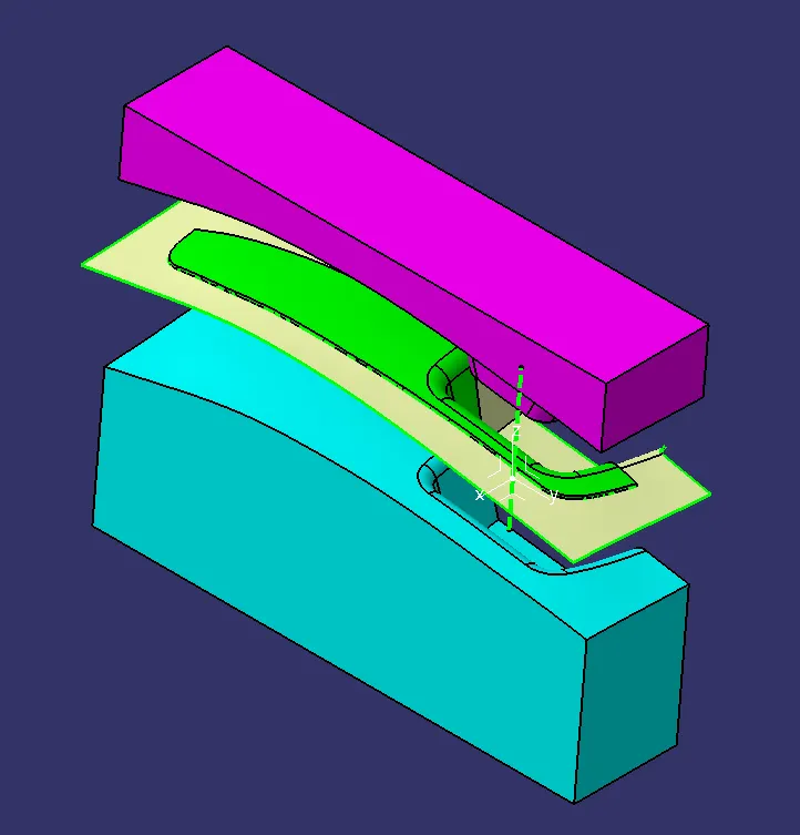
FRONT View:
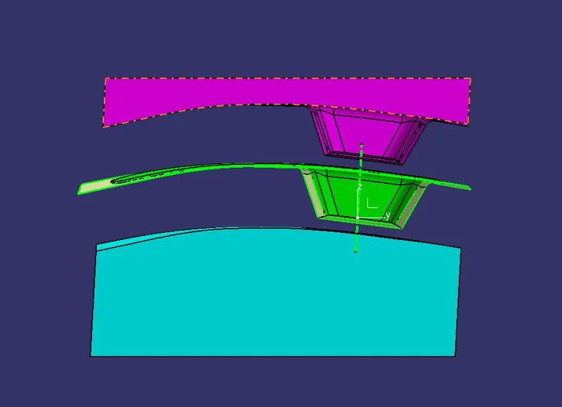
BACK View:
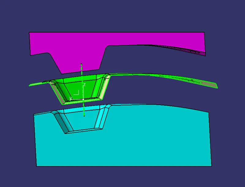
LEFT Side View:
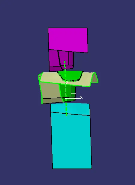
RIGHT Side View:
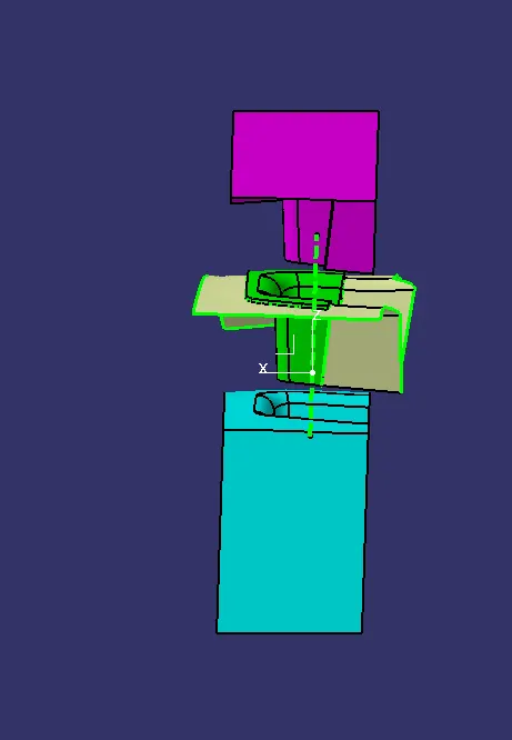
TOP View:
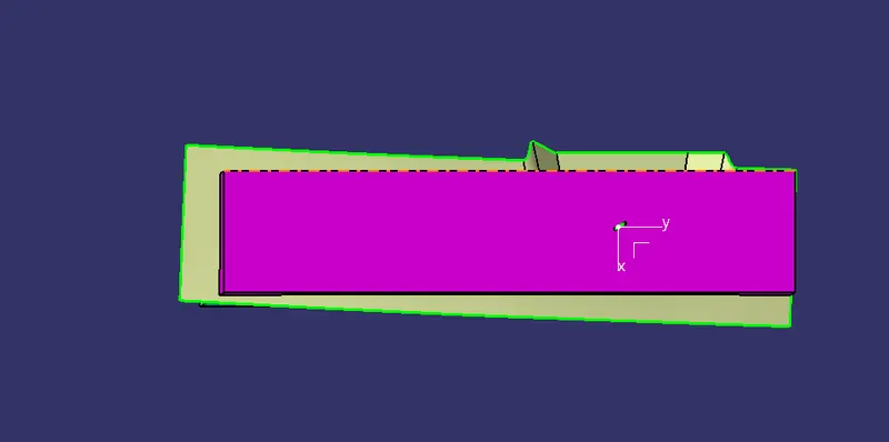
BOTTOM View:
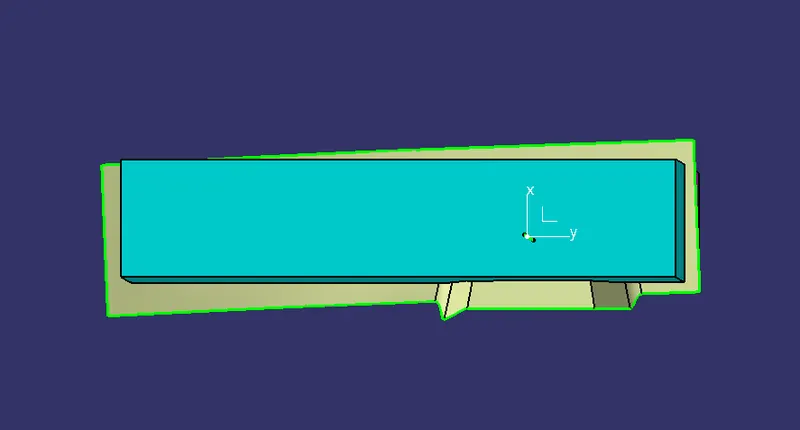
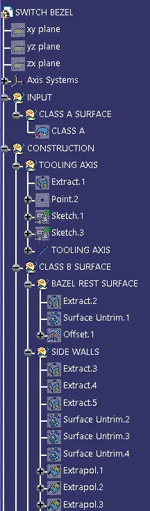
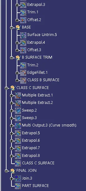
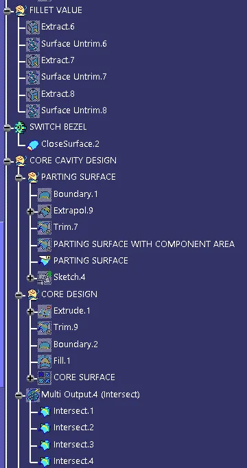
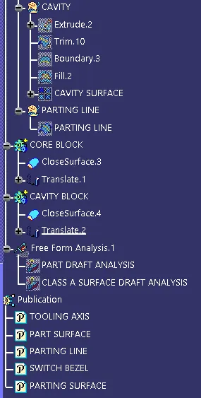
TREE Structure: