Week 9 - Attachment Feature Creation (Ribs & Screw Boss) - Challenge 1
AIM: To Design of Ribs and Screw Boss for Drill Handle following the design rules in given class A surface. And perform Rib root thickness analysis and draft analysis on the final component.
Consider the thickness of the component is 2.5 mm.
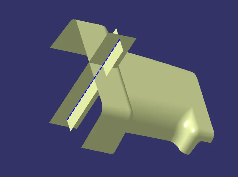
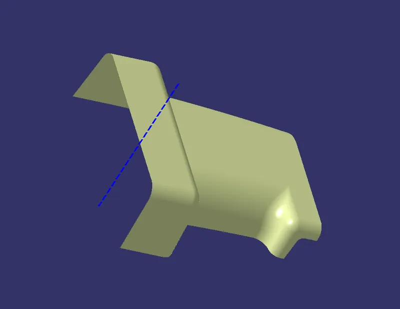
Tooling Axis:
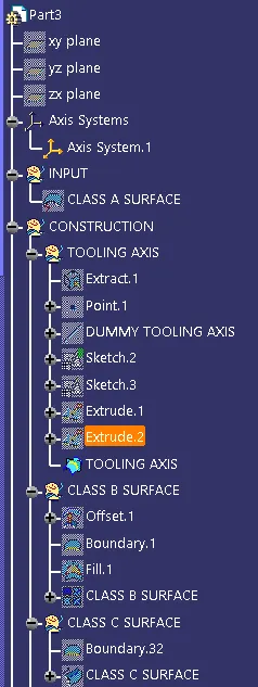
For tooling axis first we need to select the larger area of the surface and using extract command the surface is extracted. after that taking the point on the surface and then creating a sketch in the different plane and extracting that sketch and getting the intersection line which is called tooling axis.
Draft Analysis of Class A Surface:
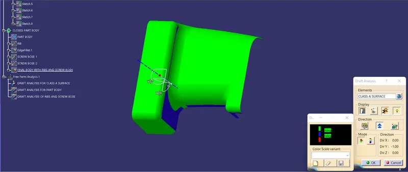
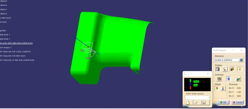
For draft analysis of class A surface first of all go to the insert and select analysis and feature draft analysis. Here in the option we need to first go to the material mode. After that select the calss A surface for the draft analysis and give the axis system to the inline of the tooling axis and then give the value of the draft angle in the bar. here, I give the draft angle 3 degree. The result in colour based that the surface which green (means draft angle > 3 degree) is right. And where the colour is blue mean draft angle is 3 degree to 0 degree if this surface area is low then you can go. If you find red colour zone then it means draft angle is less than 0 degree.
Here I give a 3 degree draft angle. But some area is looking blue which is not good. We can not change the design because it is Class A Surface which is already designed. When I give 0.5 degree draft angle then everything is fine. So it may be acceptable.
When draft angle is 3 degree. The surface is as below image:
When draft angle is 0.5 degree
Closed Surface Design:
For creating close surface we first need to create class B and class C surface using the given class A surface:
Class B suface:
For creating class B surface we must need to offset the class A surface to 2.5mm in the below of class A surface. After that we can see some manifold which we must need to close by using different surfacing command.
And Finally we can create the class B surface as below image:
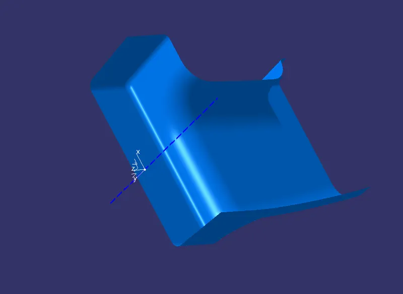
Class C Surfcae:
Now after completion of class B surface we need to create class C surface and for that we need to create the boundry and sweep of the class A surface. After sweep and extrapolation and trim we can join the class C surface as below image:
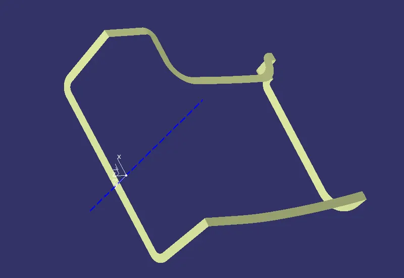
For creating the close body we must need to first join the class A and class C surface.
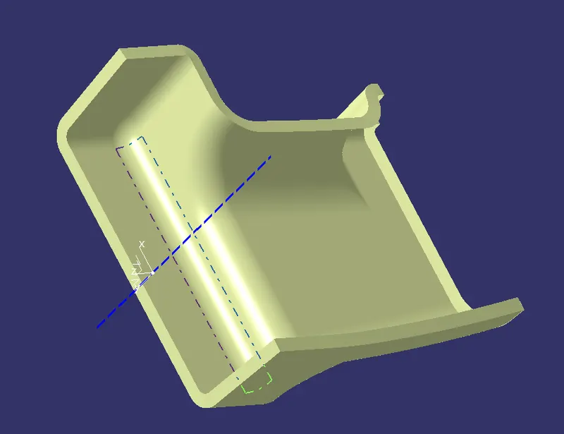
After that we need to extrapolate the boundry of the class B surface and then using trim option we can trim that to the combination of class A and class C.
And finally we get the close surface as below image.
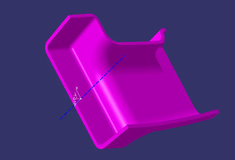
After completeing this we going to the part workbench and using the close body command we create the part body for the required surface.
Rib Design :- Ribs provide a means to economical stiffness and strength in molded parts without increasing overall thickness. They also facilitate Locating and arresting components of an assembly and Providing alignment in mating parts, also Acting as stops or guides for mechanism.
Proper Rib design involves many issues which is consider carefully when designing-
Thickness, Height, Location, Quantity, Manufacturability
General Guidelines for Ribs on Shown Surfaces
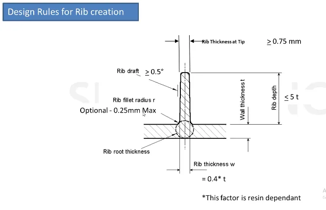
Draft - 0.5 degree per side minimum
Thickness - Typically 40% wall thickness
Height ≤ 5 x wall thickness
Spacing - 3:1-steel hieght / width ratio maximum
Thickness at the top ≥ 0.75mm
Optional Radius - 0.25mm maximum
Rib root thickness should be under deviation of +-30% from the wall thickness
Ribs should be spaced so that the steel between the ribs is at a
Height / width ratio 3:1 steel 2:1 is preferred
First, the base surface where the rib has to be created is extracted using the Extract command. A positioned sketch is created and the profile for the rib is drawn.
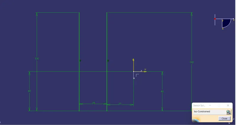
Next, the profile is extruded, to find the height, h=Wall thickness * 5
=2.5*5
= 12.5 mm
Therefore, the height is 12.5 mm
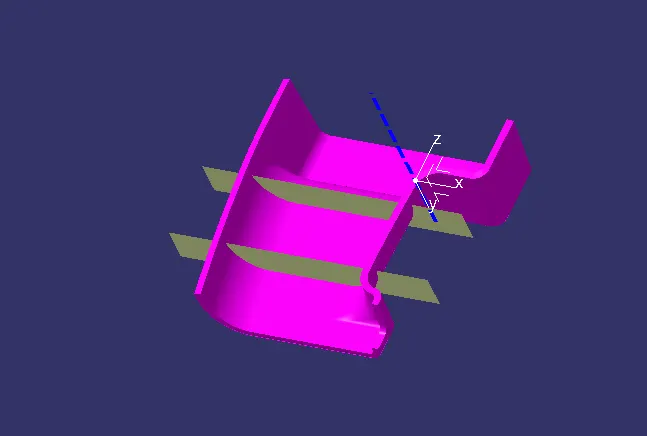
The extruded surface is thickened,
Thickness, w=0.4*t
=0.4*2.5
=1mm
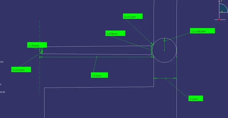
I have Designed the ribs which cross-section analysis is here for checking purpose that everything is ok or not. I fond that everything is ok.
Screw Boss :- Bosses find use in many part designs as points for attachment and assembly. The most common variety consists of cylindrical projection with holes designed to receive screws, threaded inserts, or other types of fastening hardware.
General Guidelines for Bosses-
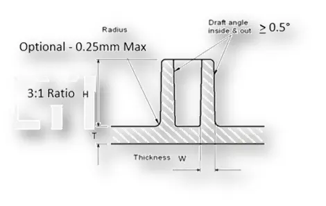
Draft (0.5 degree on the walls of the boss)
Thickness (W= 0.6xT)
Height of Diameter Ratio=3:1 (H/B < 3)
Optional Radii ( 0.25mm Maximum)
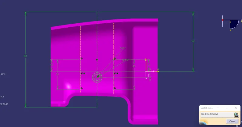
To create a screw boss, first, create a sketch and Iso-constraint it.
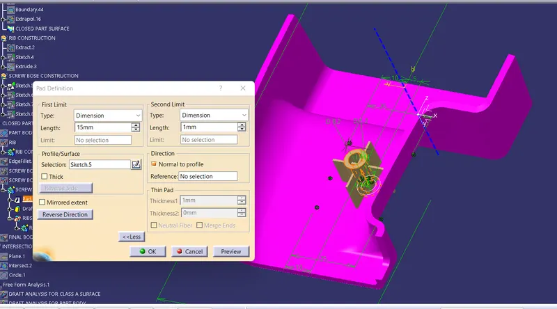
Pad the sketch to a height of 15mm as per 3:1 ratio.
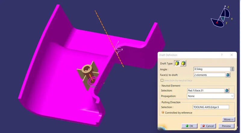
Then draft it with a min of 0.5 deg both inside and outside.
The boss is created but needs some support. So, we created ribs for support. For that First, I draw a sketch and Iso-constraint it.
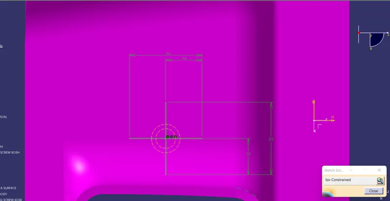
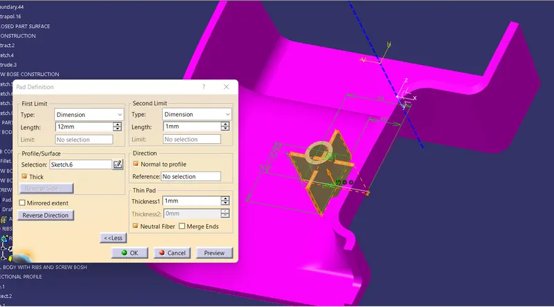
Now pad the ribs to a height of 12mm and second limit to 1mm select it as neutral element.
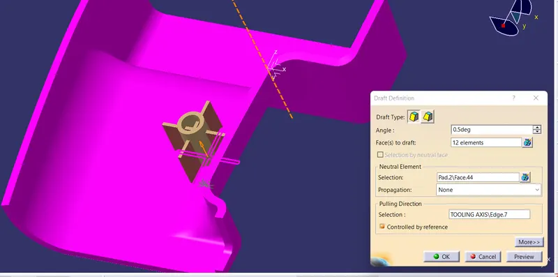
Now the ribs are drafted to 0.5 deg angle all sides.
Trim the screw boss with the ribs.
Assemble the screw boss with the coin holder.
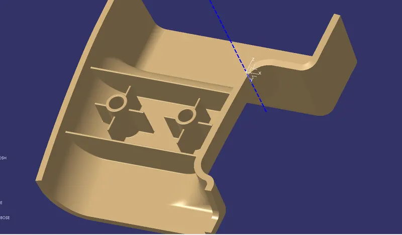
Now give edge fillets to the edges of about 0.25mm.
The screw boss with ribs is attached with the door handle.
Similarly, to create another one copy the screw boss and past it in main part body then translate it.
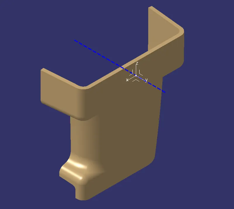
Door Handle Component with Rib and Screw Bosses with Gussets :
Iso View:
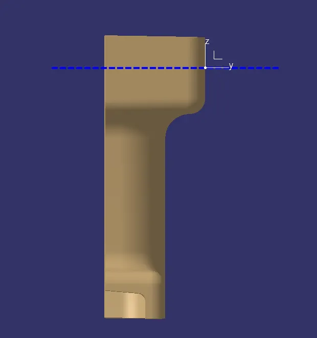
Front View:
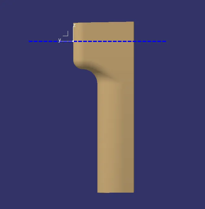
Back View:
Left side View:
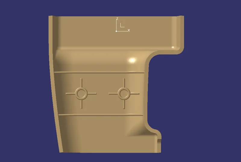
Right side View:
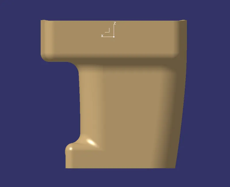
Top View:
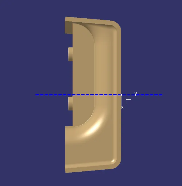
Bottom View:
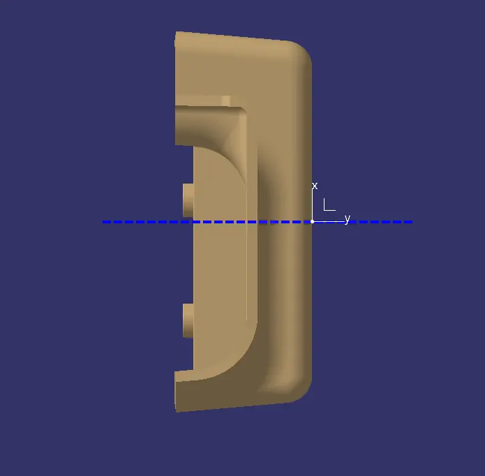
Draft Analysis :-
The Draft Analysis allows the user to easily analyze a part for proper draft angle. A Draft Angle describes the amount of taper for molded or cast parts perpendicular to the parting line. Draft Analysis is applicable for 3D part models. To create a draft analysis for any 3D part file, the user needs to select part/surface and select the pull direction. You can change the pull direction.
Draft Analysis of Door Handle :-
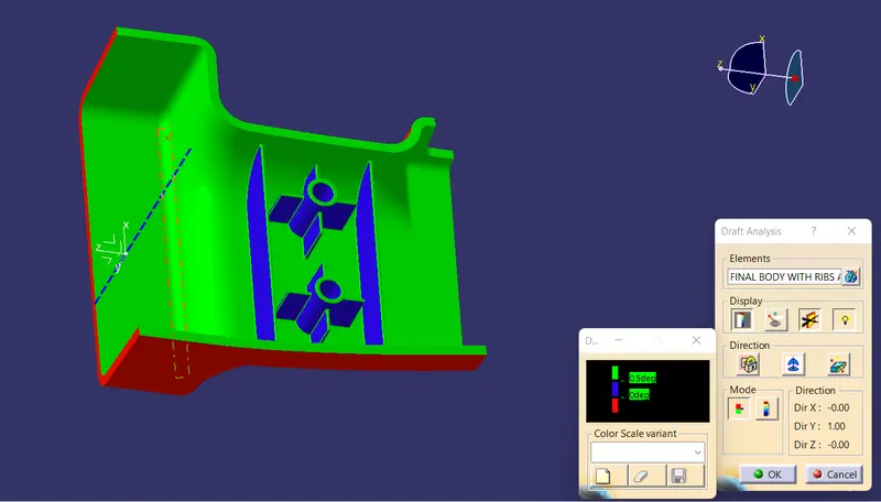
In above figure ribs, bosses and gussets are in blue because I have give 3 degree draft angle while in ribs, bosses and gussets have 0.5 degree draft angle. So in below figure I have given 0.48 degree draft angle for draft angle. So whole body is ok.
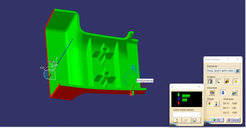
Draft Analysis of the part in diffeent View:
Iso View:
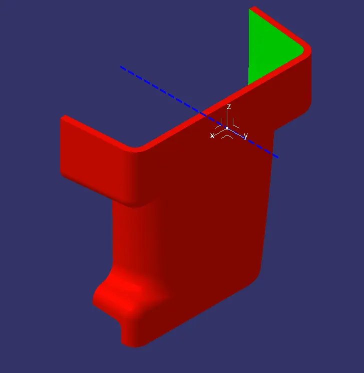
Front View:
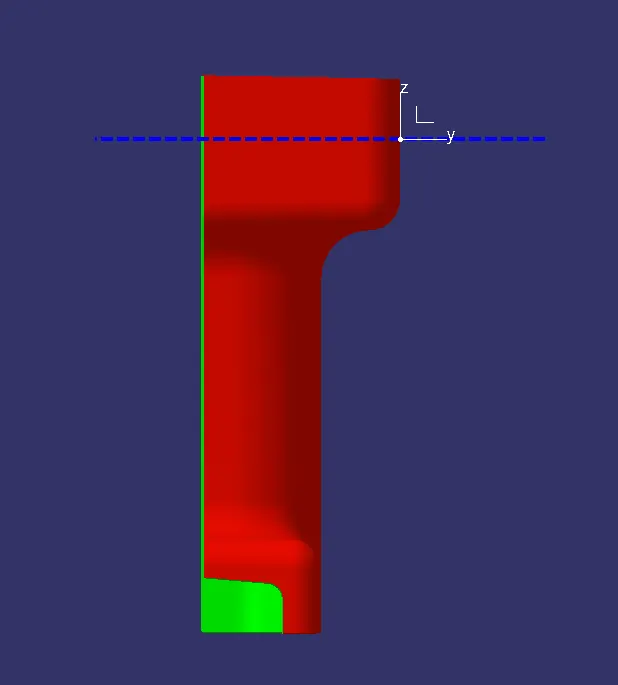
Back View:
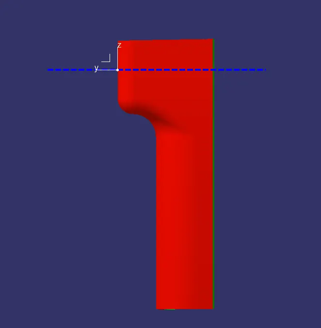
Left Side View:
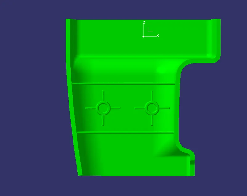
Right Side View:
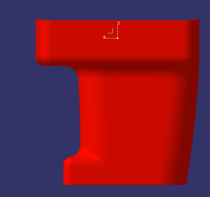
Top View:
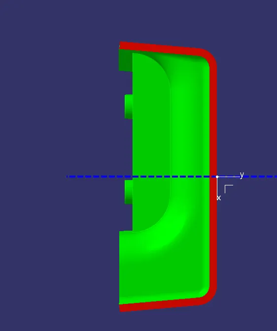
Bottom View:
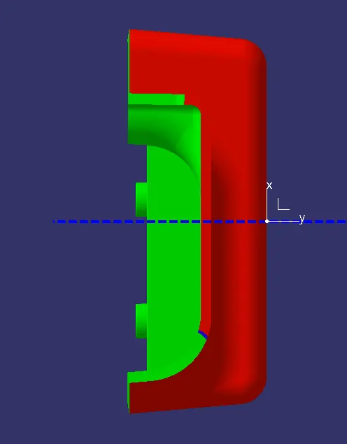
Here, we can see that in the some portion of the class C surface becomes red due to the perpendicular to the tooling axis the draft angle is perpendicular thats why its shows in red color.
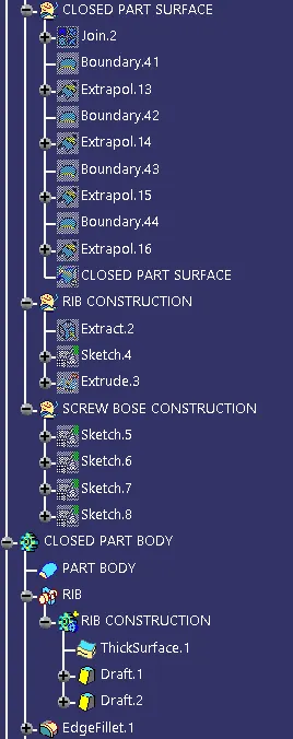
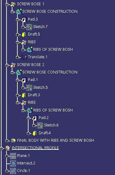
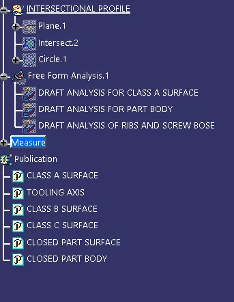
Feature Tree of This Part :