Wiring harness routing & packaging Rules Week 3 Challenge
1) P-CLAMP :
First I have to download the given igs file and open it in the CATIA V5 software.
Now go to the part workbench and defining some geometrical parameter.
First of all I am defining the point where the bundle entry is done. here in the P-clamp from both side we can enter the bundle. So Both side I am defining point.
Go to the point and take the circle center as a point and select the face of P-clamp.
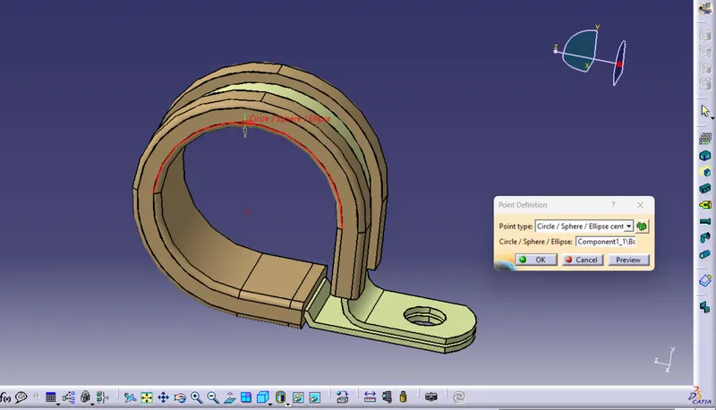
Same as take the second point from second side of the P-clamp
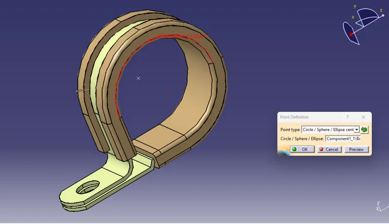
Now,both point defining is done.
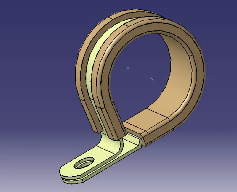
We need to define plane for the bundle entry point and for base of the clamp where the bundle is in resting position.
For creating plane for bundle entry click on the plane and select the point and face.
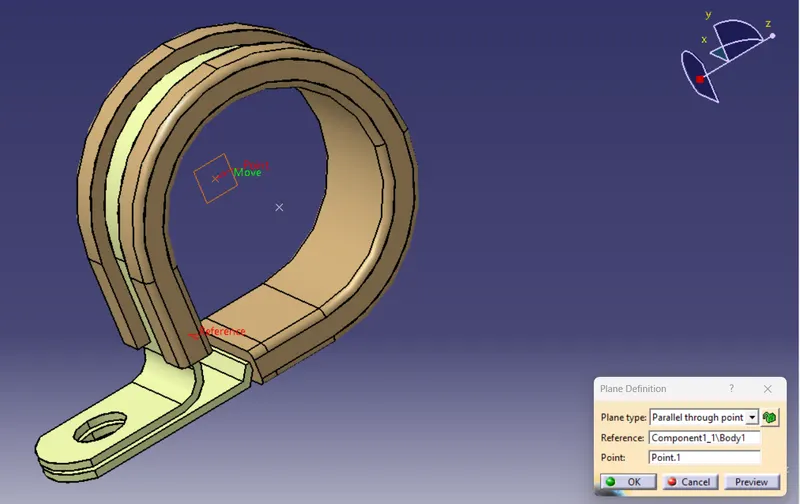
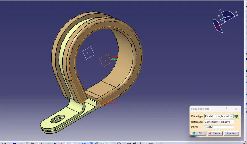
Same doing in the second side.
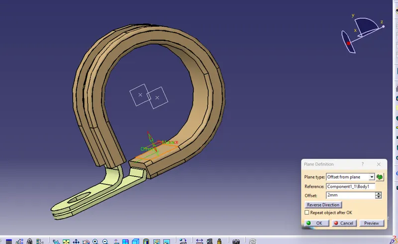
For resting plane select the base surface and take some offset and creating plane.
Now all required geometrical parameter is defined. Now go to the electrical part workbench and define the P-clamp as support system first.
click on the icon of define support system and click on P-clamp the dilouge box is open as per below image.
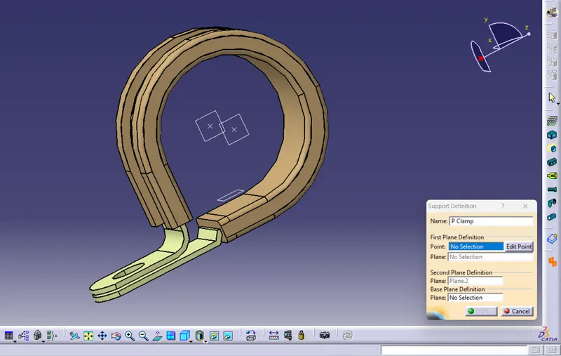
Now, In this dilouge box first point select the one point and in the plane select the plane 1. In the next option select the second point and then select the base plane and click on ok. so , first entry for the bundle is define in the P-clamp. Same as for the second time select the another point and plane. Here, this time second point is selected by deaufault so select the base plane and click on ok. So second bundle entry is define.
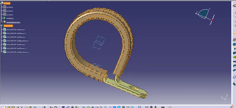
Now, save the P-clamp.All required electrical paramter is defined.
2) BACK-SHELL :
First of all we need to download igs or stp file for the given part. for that we need to go to the website and in the document section there in the CAD files we can found the required igs or stp file and click on the link and download it. After downloading is complete unzip the file in the seperate folder.
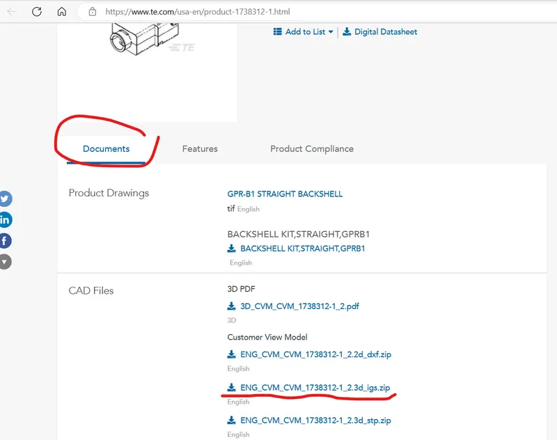
Now Drag and drop the igs file to the CATIA V5. After that drag and drop the files in CATIA V5 software so the model of the Backshell is open.
Now here first the model is open in the part workbench.
and we required to define some geometry parameter of the model first in the part workbench.
First we need to define the Backshell connection point and the bundle entry point. After that we need to define axis system for the backshell connection point which is same as compatible connector's axis system.
After this defining the all required parameter I have to go to the electrical part workbench.
Then in the electrical part workbench first I have to define the Backshell. So click on the define backshell icon and select the part.
After defining the backshell we have to define the backshell connection point,bundle connection point and save the models.
1)first drag and drop the model C-1738312-1-2-3d in CATIA V5 and open the model.
After that ensuring that it is in the part workbench.
Now for first we are create the Backshell connection point . For that click on the point and select the face which is connected to the connector. and create a point in the middle of the face by using the face geometry.
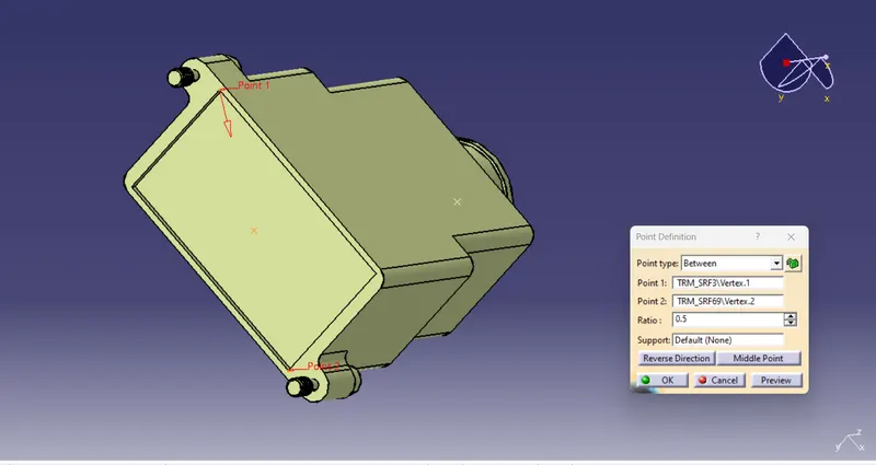
After click on OK button we have found the point on the surface of the Backshell and I am rename the point as backshell connection point.
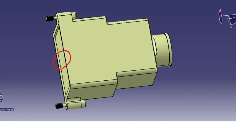
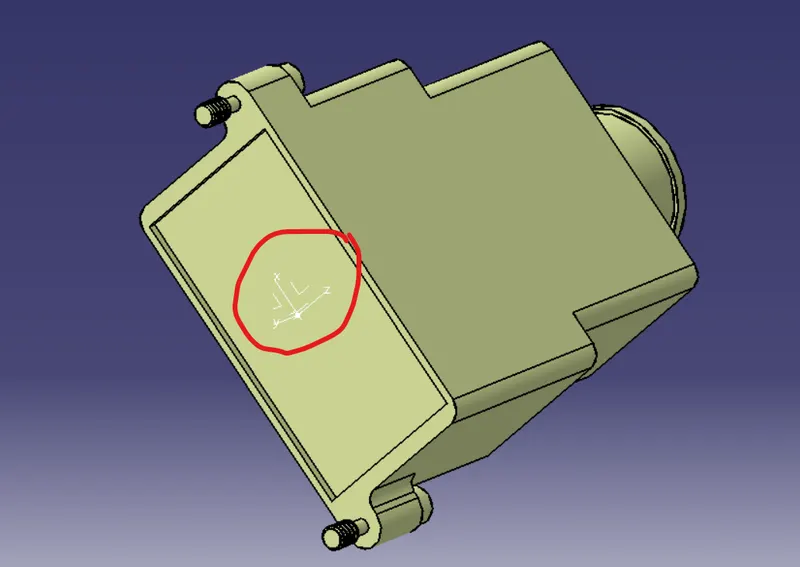
After getting backshell connection point we need to define the backshell connection axis. For defining the axis click on the axis system and put the Y-axis in the direction towards the face which connect to connector and the X-Axis is towards the locking mechanism. After that click on ok.
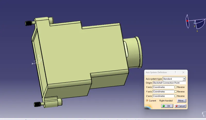
After click on ok axis should be defined as per below image.
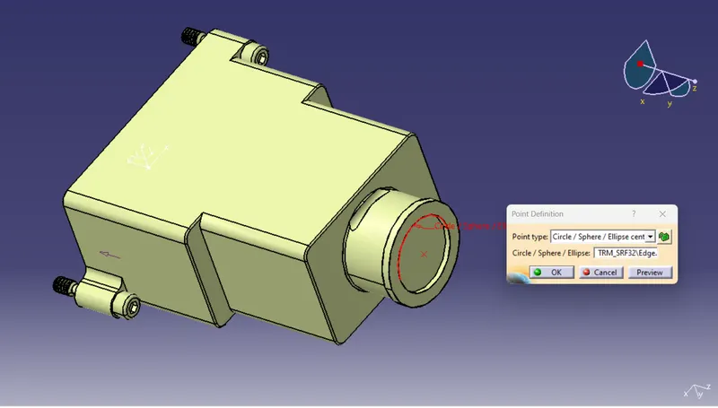
Now defining the bundle entry point. for that same as taking a point on the end face of the backshell from where the bundle entry is done. As per below image give the input and click ok.
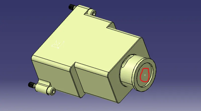
The bundle entry point is created as per below image and renaming it.
Now all required geometry parameter is define. Now go to the electrical part workbench and we need to define the backshell as electric part. For that click on the define backshell command and select the part. give the name of the backshell and give the input in extra length as unset then click on ok as per below image.
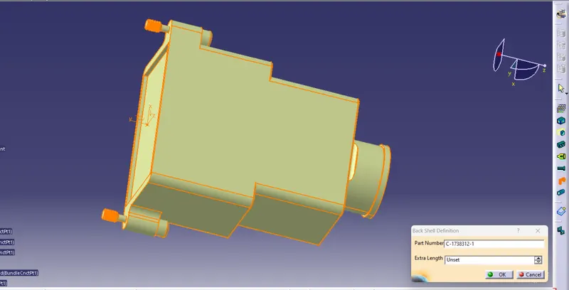
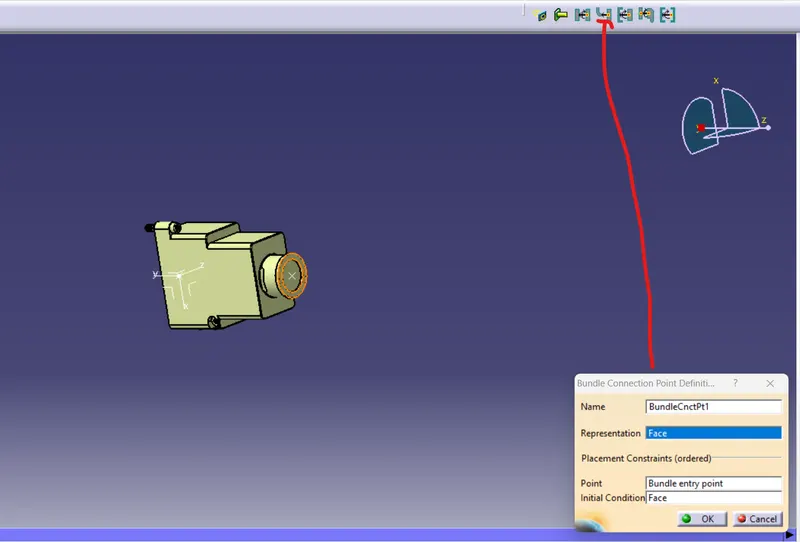
After defining the backshell as electric part we need to define the parameter of the backshell in the electtric part workbench. So, first I am defining the bundle entry point. Click on the icon as shown in the below image and give the input as per the below image and after that click on ok button.
Same as we have to define the backshell connection poin for that we have to select the coinsidence axis as the Y -axis and orientaion as X-axis as per the below image give the input and click on ok.
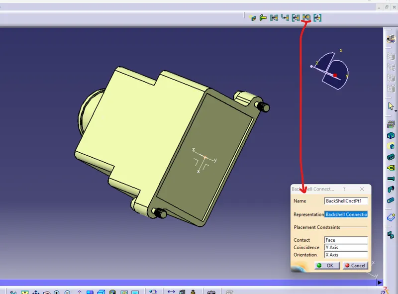
After click on ok button the all required parameter is defined and click on the save button and save the backshell.
3) Corrugated tubes :
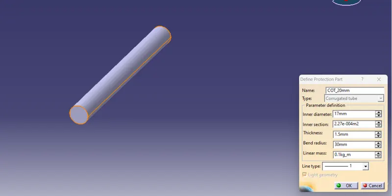
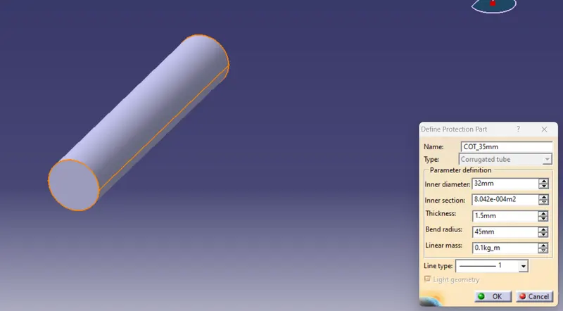
For creating corrugated tube first of all open the CATIA and create new part design. and here go to the electricl part workbench. and cclick on define protection part icon shown in below image. and then click on the part at tree structure. the dialouge box is open as per below image. then enter the input values in the dialouge box and then click on ok button the corrugated tube is created and save it.
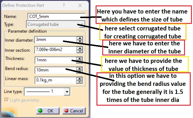
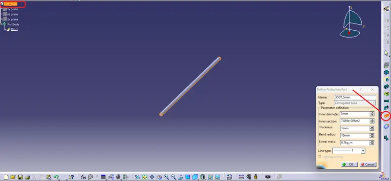
Now In this way using the all of above parameter I am creating different size corrugated tubes and save all corrugated tubes in a same folder. As shown in below images all the input parameter for the different corugated tubes.
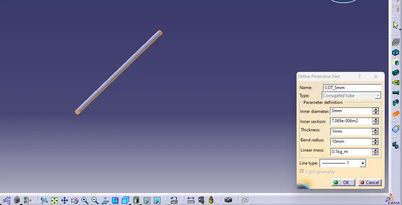
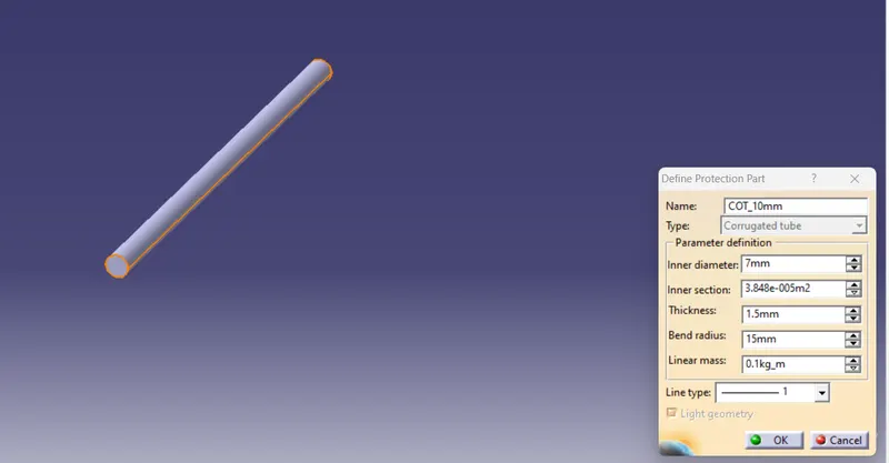
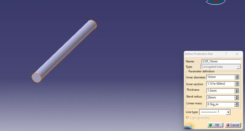
Catalogue:
For creating catalouge first of all open the CATIA and click on File -> New here from the option select the catalouge document and name it as Slit COT and click on ok button.
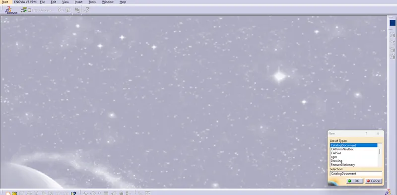
After click on ok button the window open as per below image. here from the icon click on the icon of the "add new family" icon.
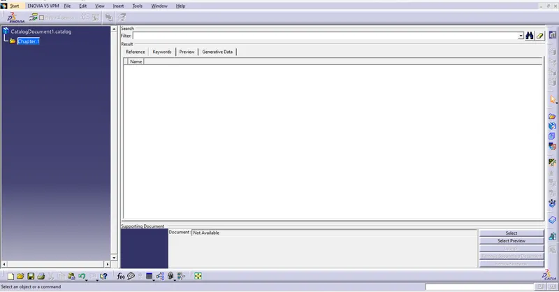
In the below image shown the icon for the add new family and click on it and the dialouge box open as per the below image, in this dialouge box first of all give the name of the family as "Slit COT" and the in the below option there are many option for the type of family.
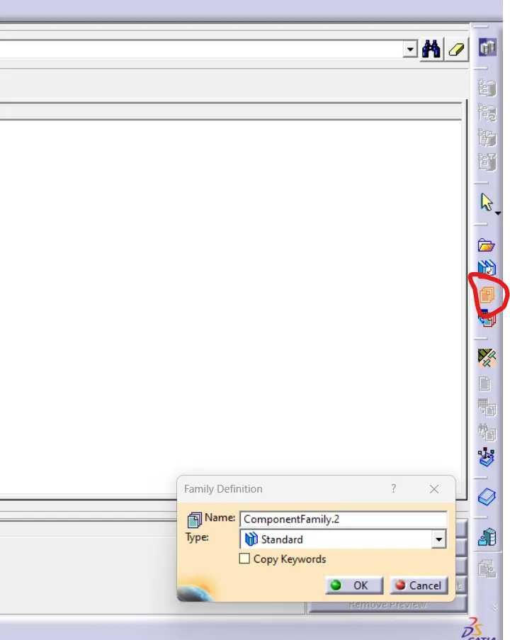
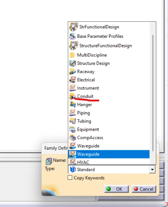
From that dropdown menu select the "conduit" because the corrugated tube type is conduit. After select the type click on ok button. And if there is any sub family you can add. or else save the catalouge at the same folder where we have save the all corrugated tubes and close it.
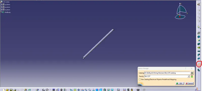
Now for adding the all tubes in the catalouge , we have to open the all corrugated tubes and here in the option we can see the icon for the "device storage" as shown in below image. click on that icon and dialouge box is open here in the first option catalouge select the location where the catalouge is save and select the catalouge. then in the second option family select the "Slit COT" family shown in drop down menu. and then click on ok button the corruagted tube is stored in the catalouge browser.
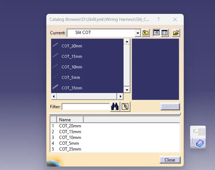
Now to see the catalouge we can accecess it in the assembly workbench. here there is option for the catalog browser as shown in the below imageand select the catalouge and select the family in the drop down menu here we can see all the corrugated tubes which is added in the catalouge.