Fender Design
OBJECTIVE :
The main object of this project is to design the BIW(Body in white) of front fender using the fender skin data and master section and also design the Drip mounting, A-pillar, Sill, Bumper and Baffle (splash) Mounts using NX.
WHAT IS FENDER?
A fender is a body panel covering the space over the wheels. It’s attached to the side of the vehicle, and its primary purpose is to protect your wheel assemblies and suspension components from sand, mud, rocks, liquids, and other road spray from being thrown into the air by the rotating tire. They “fend” off the danger. Fenders are typically rigid and can be damaged by contact with the road surface.
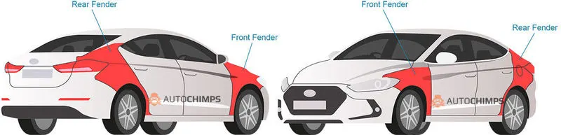
Sticky materials, such as mud, may adhere to the smooth outer tire surface, while smooth loose objects, such as stones, can become temporarily embedded in the tread grooves as the tire rolls over the ground. These materials can be ejected from the surface of the tire at high velocity as the tire imparts kinetic energy to the attached objects. For a vehicle moving forward, the top of the tire is rotating upward and forward, and can throw objects into the air at other vehicles or pedestrians in front of the vehicle.
TYPES OF FENDER :
There are two types of fender classified based on the area covered.
- Full Bumper Type
- Half Bumper Type
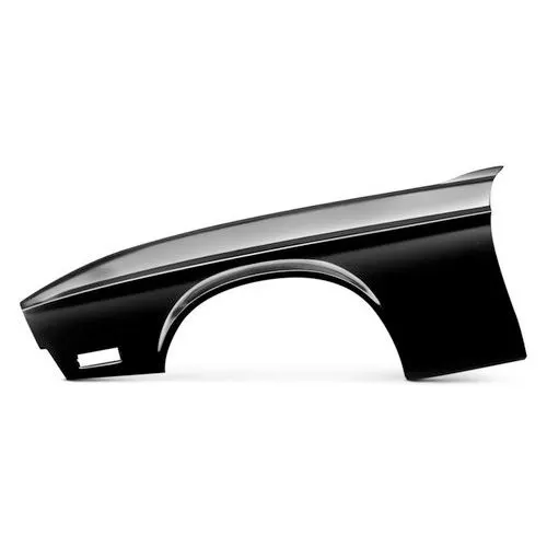
1)Full Bumper Type:
Full Bumper type is traditional type of fender where more material consumption is observed. This type is used in old design of automobiles where it increases the overall weight and thus reduces performance. The maintenance also relatively more due to more surface area. While manufacturing this type of fender it produces the more scrap and also more waste of material because it require bigger size blank to produce the part. So nowdays this type of fender is not commonly used because it is not economically good for manufacture.
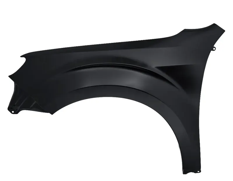
2)Half Bumper Type:
Half Bumper type is modern design where less material consumption is observed. So productivity increses by reducing size of blank and thus providing more performance. The maintenance also relatively low compared to full bumper type. This types of fenders are most commonly used because the waste of material is less & can produce two fenders at the same time by slightly increare the raw sheet also to reduce the weight & cost.
APPLICATION OF FENDER :
- It limits the exposure of Car body and engine to external elements Which is harmful.
- It provides safety to the driver and passengers at the time of accidents or collisions. They are manufactured in a way to provide bend during front and side collisions.
- Fenders flares are attached to ensure that both the body and engine have minimal contact with corrosive elements.
- It helps to avoid wind resistance and make your car more aerodynamic. Also it give the more asthetic look of vehicle.
MANUFACTURING PROCESS :
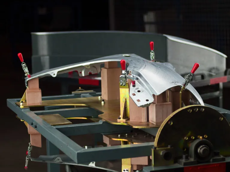
Metal stamping manufacturing processes can quickly and cleanly create solid metal parts and forms. The process uses specialized dies that press sheets of metal into precisely the right form. Auto manufacturers benefit from using metal stamping for parts like fenders and hub caps because the dies can be used again to create consistently sized and shaped parts that meet tight specifications and tolerances. Some key benefits of metal stamping include:
Cost-Effectiveness: Once the dies have been made, manufacturers can create high-volume runs of automotive parts at a low cost. Metal stamping techniques can handle a variety of metals, which allows companies a large degree of flexibility without additional costs. The metal stamping dies themselves are also cost-effective to create and keep in good working condition. The finishing steps of producing the parts, like plating, are also cost-effective.
Material Efficiency: Metal stamping processes use sheet metal to create parts. Sheet metal is efficient and doesn’t add wasteful heft or thickness to the part. Sheet metal can be used for an array of parts, including structural elements, the chassis, and mechanical components in the engine or transmission systems.
Automation: Metal stamping processes can be handled entirely by machinery. Not only does this reduce the risk of human error or inconsistency, but it also lowers labor costs and keeps employees safe.
Types of Metal stamping Process:
There are three popular types of metal stamping presses used for automotive and other industrial parts. They include:
Mechanical presses: which have a mechanical flywheel powered by a motor.
Hydraulic presses: which have pressurized fluids that control the pressure and application of force on a workpiece.
Mechanical servo presses: which use only motors and no mechanical flywheels.
Material Used for metal stamping process:
Some of the most commonly used metals in stamped automotive parts include aluminum, copper, and steel. Each metal has unique attributes that make it ideal for certain applications.
Aluminum: Manufacturers use aluminum for visible parts and details because of its attractive appearance and light weight. Companies can also easily form alloys with aluminum and other metals to make stronger or more durable varieties.
Copper: This metal resists corrosion, is ductile, has an attractive finish, and is affordable. Companies can also choose copper for environmentally conscious customers; the metal is easy to recycle and reuse.
Stainless Steel: This metal resists corrosion and rust because it has a makeup of at least 11% chromium. Not only does it have increased durability, but it also has a lustrous, attractive surface.
Steel and Steel Alloys: Steel alloys come in many different varieties, such as mild steel, high-strength steel, and specialized steel that can be used to create a variety of durable parts.
FENDER MOUNTING AREAS :
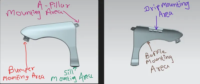
There are majorly five mounting areas in fender which is named in below.
- Drip Mounting Area
- Bumper Mounting Area
- Sill Mounting Area
- A-Pillar Mounting Area
- Baffle/Splash Mounting Area
DESIGN CONSIDERATION:
For designing the fender first needs to open the given fender skin data and also provided the master section which we need to follow.
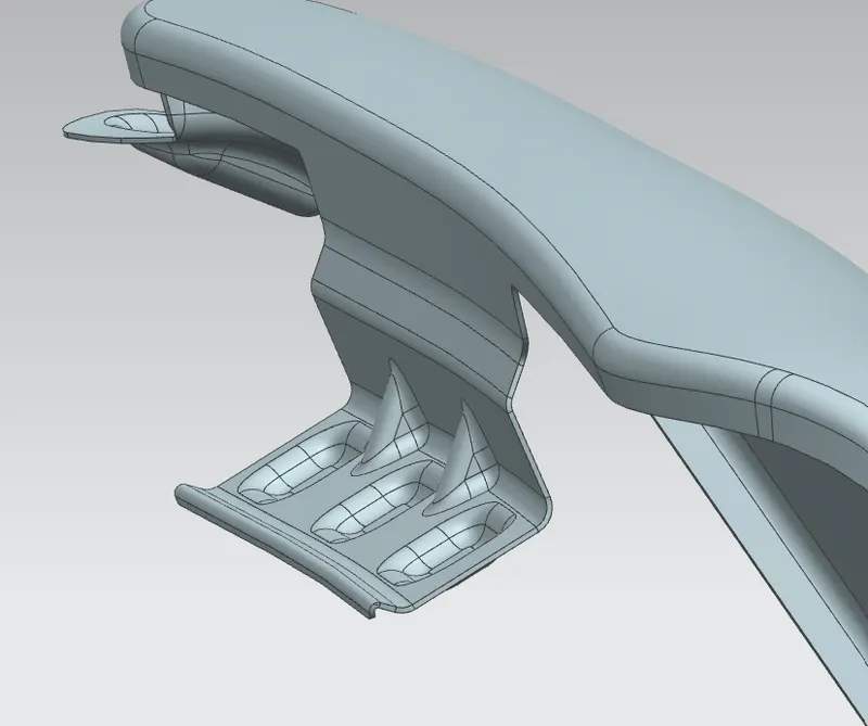
1)Drip Mounting:
It is most important mounting unit of a fender. Its connected with the engine compartment and therefore a lot of design constraints are to be followed while designing the drip area. whilw designing the drip area mounting we need to maintaing proper gap between hood and the fender which shouldn't be visible for human eye.
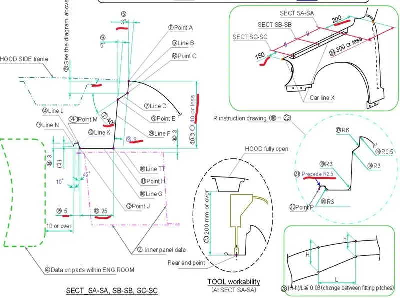
- Here,In the master section 3° Angle is given which is used for stamping purpose as well as it is used for Good Spring back effect.
- Now, 8mm distance is given at 40° which is providing for improving the appearence of parting gape between hood and fender.
- The length of the drip area is given 40mm or less for production purpose because if the length is increase it doesn't hold good spring back effect as well as it shaking and production is not feasible in this case.
- Where the Bolt or Fasteners is mounting the area 25mm width is provided which is the minimum value given for accessing the tool to fix the fender with engine room using fastners or bolts.
- In the end of the drip area 5mm distance with precede R2.5 is for the strength given to the structure.
- From the back side of front fender, there will be 200mm clearance for cowl(wiper motor assembly) mounting area and
- from the front side of front fender, there will be 150mm clearance for head lamp housing unit.
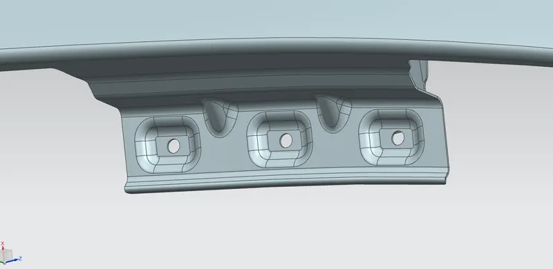
- Here in the fender design Embosses are provided to increase the strength and Smooth curves are designed for easy manufacturing of panel.
- By using the Ribs we can provided structual support and extra strengh. also we have to consider to Maintain extra 10mm from the flat surface for the fastner holes.
Procedure:
- First we need to import the given skin data and identify the region where the all mountings are located.
- After that Offset the face at 5mm and draw the curve on surface to trim off the extra surfaces.
- creating datum plane on curve and give the distance 150mm also offset that datum plan and give the distance 200mm from other side where we have to use the A pillar outer most edge as a reference. Using intersection curve creating a intersection curve at both datum planes and creating a curve on surface and triming off the extra face.
- Using law extension extend the surface as per the master section dimensions and then given the fillets also as per the master section.
- Now , creating the emboss for the fastners and also creating the hole and triming it . here the emboss is done in the reference of datum so we can get the flat surface for the emboss surface because we use the fastners for the assemble.
- Applying the fillets at all the edges. Now using the sewing we join the both surface and given the dart for strenghting that portion.
2)Bumper Mounting:
Procedure:
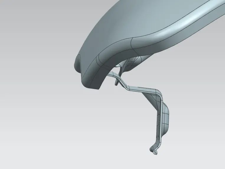
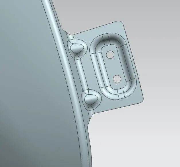
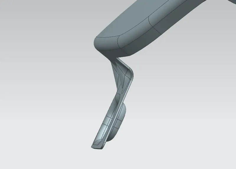
- creating the curve on surfae and trimimg the extra surface and then using the law extension need to extend the sheed as per the required distance. And given the corner smooth by using the curve on surface and triming the extra portion.
- Now take the datum plane on that extended surface and creating the sketch for emboss and hole portion. after that embossing the surface and taken the datum plane as reference and that trimming the hole. then given the radius at edge of emboss. also given the dart for strength that portion.
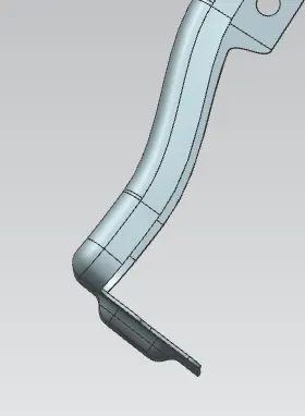
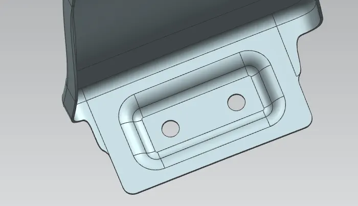
3)Sill Mounting:
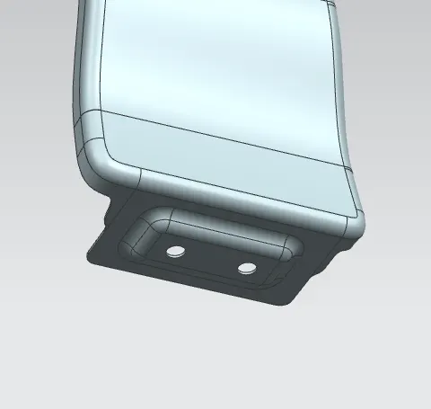
This mounting is use to link the fender with the sill (underside of the door) of the car.
Procedure:
- Here first we extend the sheet by using law extension. and drawing the curve on surface and trimming it.
- now take the datum plane at the surface and draw the sketch of emboss and hole for the fastners. after that embossing the surface in the reference of the datum plane and than trimming off the hole. removing the sharp edges by creating the curve and trimming it.
- Also gibe the redius to the emboss edges and other all edges of the surface.
4)A-Pillar Mounting:
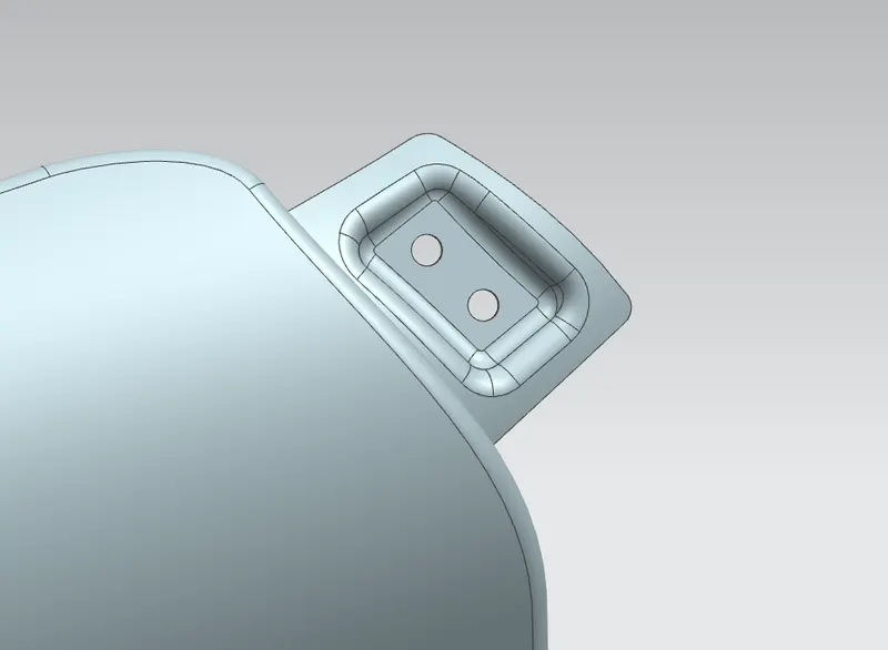
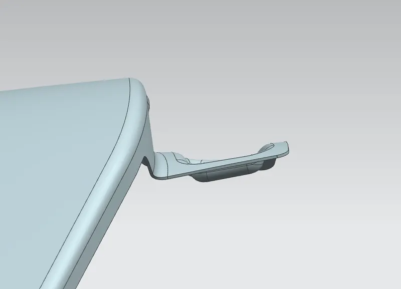
Pillars are vertical to supports on vehcile. The A pillar holds the winshield in Place.
Procedure:
- Doing the same procedure done in the Bumper / Sill Mounting
- creating the curve on surfae and trimimg the extra surface and then using the law extension need to extend the sheed as per the required distance. And given the corner smooth by using the curve on surface and triming the extra portion.
- Now take the datum plane on that extended surface and creating the sketch for emboss and hole portion. after that embossing the surface and taken the datum plane as reference and that trimming the hole. then given the radius at edge of emboss.
5)Baffle/Splash Mounting:
In order to stop all the debris entering into the engine room and other components Baffle mounting is used in some vehicles. this baffle is a plastic material component so it is assemble by using the trim clips. so, It just reqiure a area to hold the splash protector, so holes or slots are provided as per requirement.
Procedure:
- Here we draw some curves on surface and trimming it and creating the plane on surface at every portion and on that plane we create skatch and draw hole.
- then by using trim sheet the hole is trim from the surface. removing the sharp edges by creating the curve on surface and trimming the corner and also giving face blands to the edges where required.
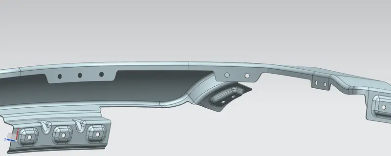
In the end of this all mounting is to be done after that using the thicken command the thickness is given of 0.75mm and then giving edge bland at some corners.
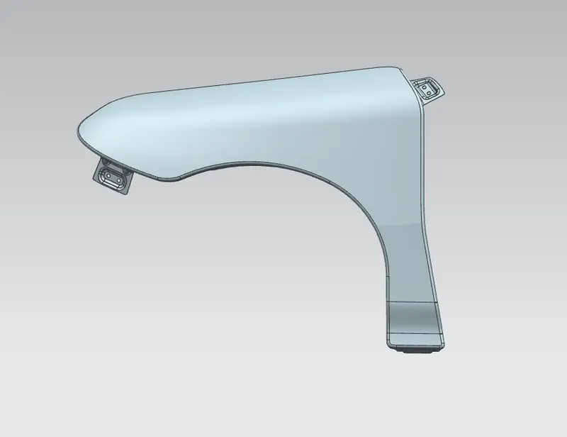
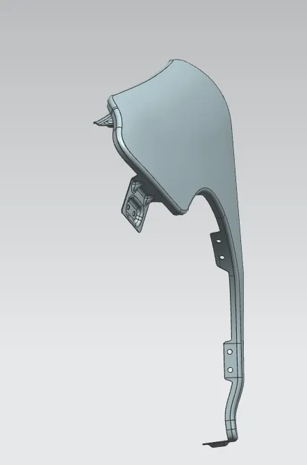
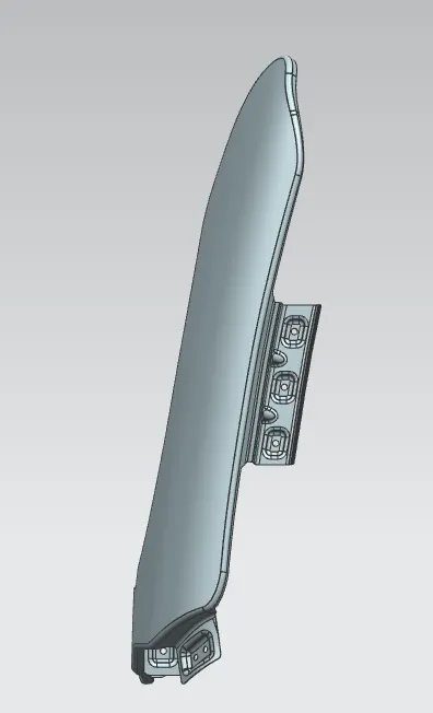
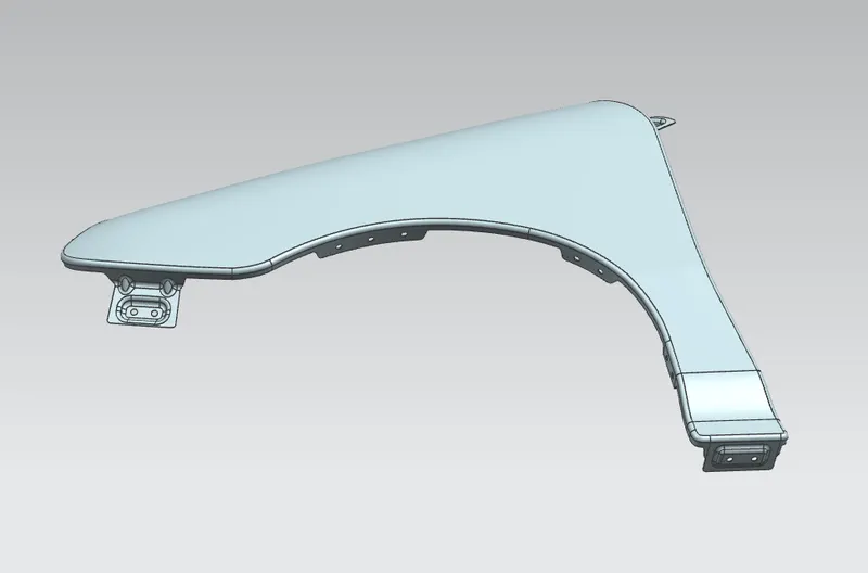
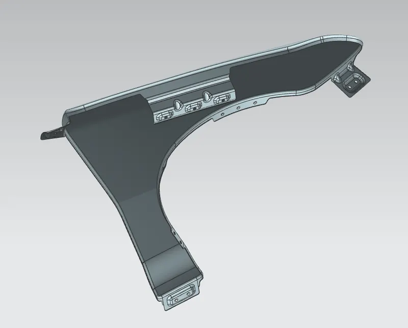
After Given Thickness The Various side orientations is shown in below images:
Front View:
Side View:
Back View:
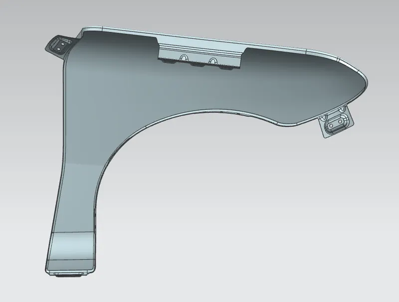
Top View:
Isomatric View:
CONCLUSION :
Thus, all moounting areas for the car front fender which is designed from given skin data and also consider the master section is done by following all design rules.