Hood design-Week 2
HOOD AND ITS COMPONENTS:
Here we are going to understand and design the concept of front-mounted engine’s hood according to the standards. The hood or bonnet is the hinged cover over the engine of motor vehicles that helps to protect the engine from rain,dust,damge etc Also it helps in pedestrian safty during crash. Also its providing easy access to maintenance and repair. So, it acts as a critical safety component both for the vehicle occupant as well as the pedestrian.
Hood includes several subcomponents, such as hood inner panel, hood outer panel, striker and the hinge assembly. but the two most important ones are the outer and inner panels. The inner panel serves as a structure for the vehicle to dissipate and channel shock waves at the event of a crash while the outer panel serves more as an aesthetic for the automobile’s overall presentation and to channel airflow over the vehicle.
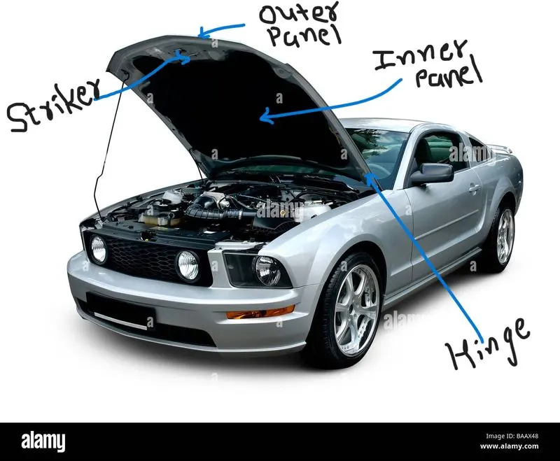
When the design for subcomponents will be finalized the manufacturing process is to be begins. Here the inner pannel is manufactured by the deep drawing process and Outer Panel is asssemble with the inner panel by hamming process.Hemming involves folding of the outer surface to overlap the portion around the inner panel and it is pressing using hemming rollers to maintain the consistancy of joining.
DESIGN CONSIDERATION:
While designing a hood several design parameters are to consider such as the opening angle of the hood, Support system for the hood, Pedestrian safety rules, etc.
The hood of most vehicles is usually fabricated from sheet metal, which is a compliant energy absorbing structure which poses a comparatively small threat. Hence, Before we start the design, let us understand the rules and regulation standards for designing the hood. European New Car Assessment Program (euro NCAP) was followed to understand the consideration and standards which we have to follow while designing a hood. EuroNCAP plays an instrumental role in raising awareness on safe and effective design for the pedestrian.
Pedestrian -Vehicle Collision
Most serious head injuries occur when there is insufficient clearance between the hood and the stiff underlying engine components. A gap of approximately 10 cm is usually enough to allow the pedestrian’s head to have a controlled deceleration and a significantly reduced risk of death. It programs and develops test series and rating systems for accessing design safety for pedestrian during impact with a vehicle.
Refere the below images for the frontal crash of a vehicle with a pedestrian.
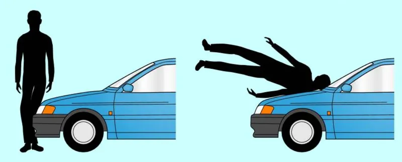
Now, here we can see that when the vehicle impact the pedestrian the parts of body will impacting on hood and the legs impacting on bumper.
In the below image we can clearly see the interaction between body and hood.
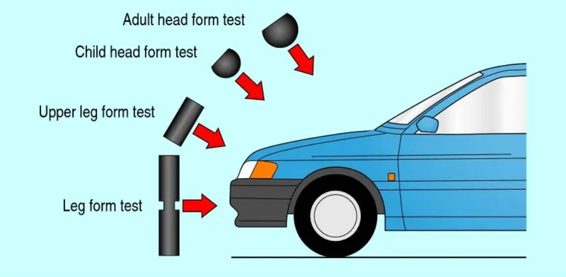
Here, in the below image the impact area for the child and adult head is to be shown. So, from this image we can consider to design the hood inner panel as soft as possible in that area so when the impact is done the most of the force is to be absorb and dissipate the energy allowing deformation and hence collapsing at that area and the reaction force should be decreased which is reduce the injury.
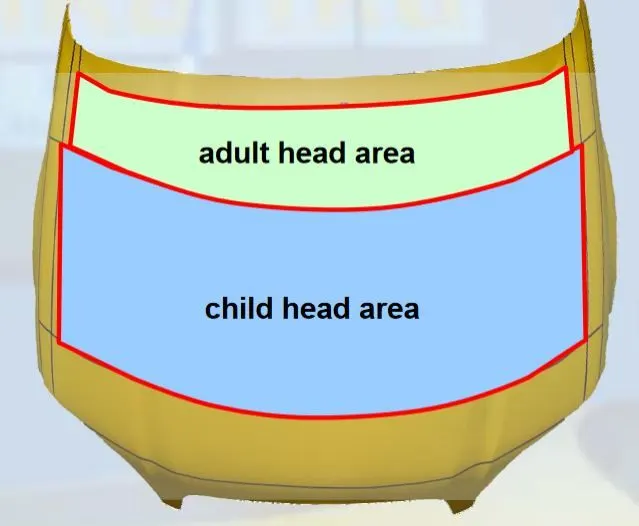
Based on these considerations, the inner panel should be embossed with strategized channels and empty cut-outs to allow for maximum absorption of such impacts. Here , Due to embossing the inner pannel the strength of the panel is increase because we use the sheet of 0.7mm so for increasing the strength and also safety during pedestrian we use the emboss and some cutouts.
Here Some design specification for the automobile Hood design is given:
- Outer Panel Thickness = 0.75mm
- Inner Panel Thickness = 0.75mm
- Reinforcement Thickness = 1.5mm
And the Master Section data is provided in the below image:
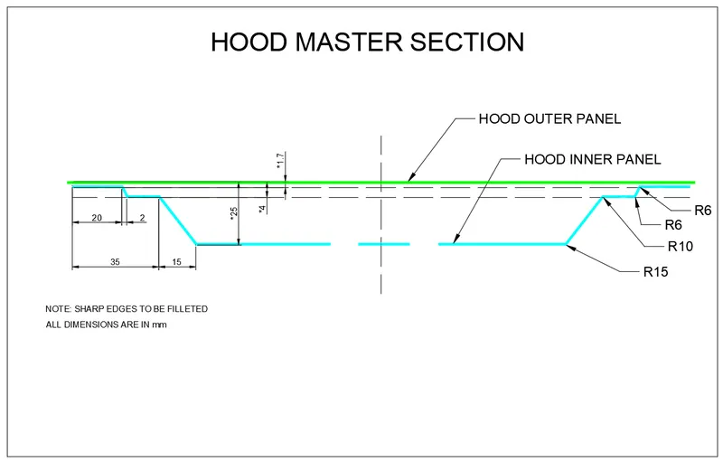
Here there is no any specific curve or design given for the hood inner panel So, we consider the given outer panel as a reference surface and by offseting that surface according to the Master section we can design the inner panel.
Shock Flow:
When designing the inner pannel according to the masrter section,the embossing was performed to strengthen the structure and also to integrate channels to direct shock flow and dissipate maximum energy away from the cabin. here by using the integrate channels we can diverte the shock flow to the A-Support so the direct impact on the vehicle body is reduced and the passangers injurie is to be reduced.
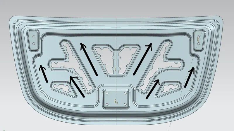
Fig: Energy dissipation to side members in a frontal impact collision
After designing of these channels , latch and hinge aseembly are placed for attachment of this structure to the vehicle. when the structure for the inner panel is done, reinforcement is provided for the placement of the hinge and striker. Now for the outeer panel to assemble with the inner panel we are not use the welding process because of the thickness of the material is 0.7 , So here we use the hamming process and we designed the outer panel as per the given hamming data.
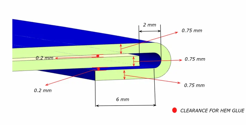
Apart from hemming, the center region of the inner panel structure is kept in contact with the outer panel using mastic sealants. Mastic sealants are rubberized components placed between the outer and inner panel to provide annexed contact. These sealants help maintain the outer panel aesthetically pleasing.
Embossing:
Sheet metal embossing is a stamping process for producing raised or sunken designs or relief in sheet metal. This process can be made by means of matched male and female roller dies, or by passing sheet or a strip of metal between rolls of the desired pattern. It is often combined with foil stamping to create a shiny, 3D effect.
Mastic sealant:
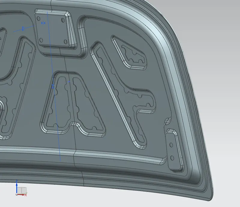
The hood inner panel and outer panel are joined using the mastic sealant instead of welding or other joining methods because the outer panel is a cosmetic part and it needs to have a smooth and attractive surface finish. The mastic sealant also further improves the flexural rigidity of the entire assembly.
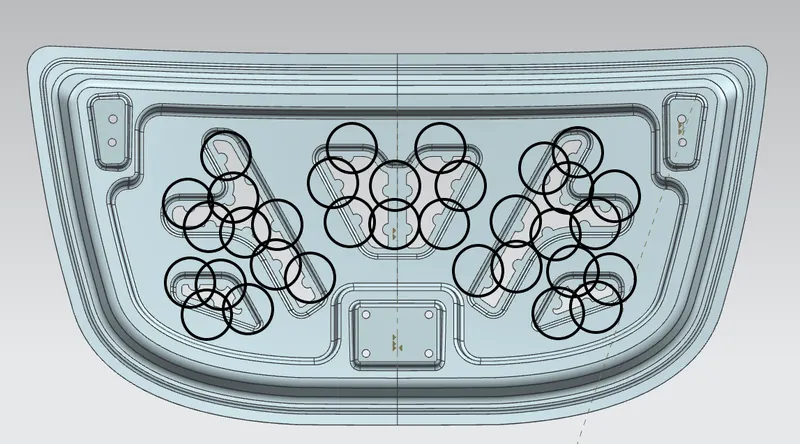
Fig: Mastic points
Deep Drawing:
Deep drawing is one of the most widely used processes in sheet metal forming. Apart from its use in many other sectors, it is applied in the automotive industry for the manufacturing of car body parts.
The deep drawing process is a forming process which occurs under a combination of tensile and compressive conditions. A flat sheet metal blank is formed into a hollow body open on one side or a hollow body is formed into a hollow body with a smaller cross-section.
Deep drawing processes are divided into three types:
- Deep drawing with tools
- Deep drawing with active means
- Deep drawing with active energy
In the automotive industry, deep drawing is usually carried out using rigid tools.
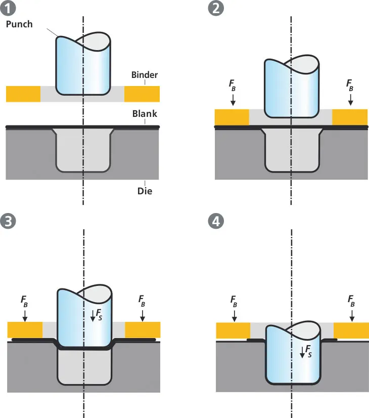
Fig:Illustration of the deep drawing process
The figure illustrates the deep drawing process. The rigid tools consist of a punch, die and binder. In deep drawing, the plate holder closes after the metal sheet blank has been inserted.
Next the sheet is clamped between the die and the binder. This process slows down the flow of the sheet while it is being drawn and thereby prevents wrinkles from forming under the binder. The punch stretches the sheet over the die radius and forms it in the die. The amount of punch force necessary for forming is thereby continually increased up to the lower dead center of the punch.
Whereas in pure deep drawing there is no reduction of sheet metal thickness, forming is achieved in stretch forming purely as a result of a decrease in sheet metal thickness. Stretch forming is extensively used for the forming of only slightly curved parts with low depth of draw (e.g. roofs, doors).
Hemming:
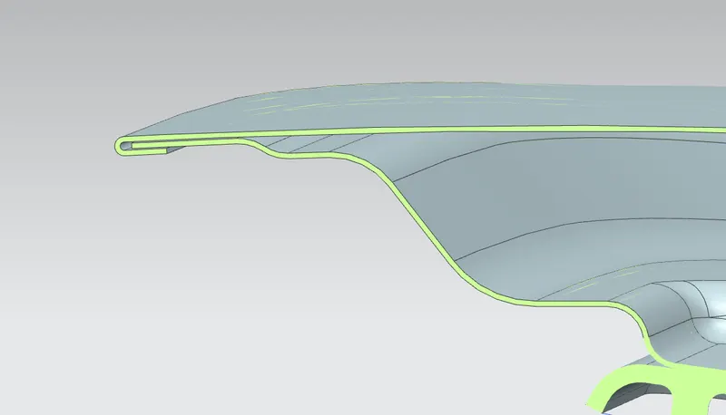
Fig: HAMMING OF OUTER PANEL OVER INNER PANEL
Hemming is a forming operation in which the edges of the sheet are folded or folded over another part in order to achieve a tight fit. Normally hemming operations are used to connect parts together, to improve the appearance of a part and to reinforce part edges.
In car part production, hemming is used in assembly as a secondary operation after deep drawing, trimming and flanging operations to join two sheet metal parts (outer and inner) together. Typical parts for this type of assembly are hoods, doors, trunk lids and fenders.
The accuracy of the hemming operation is very important since it affects the appearance of the surface and surface quality. Material deformations, which occur during the hemming process, can lead to dimensional variations and other defects in parts. Typical hemming defects are splits or wrinkles in the flange, material overlaps in the corner areas or material roll-in. This is why it is important to use simulation tools in order to, on the one hand, better understand the hemming process and, on the other hand, significantly reduce the number of “trial and error” loops during tryout und production.
There are various types of hemming operations:
- Conventional die hemming
- Roll hemming
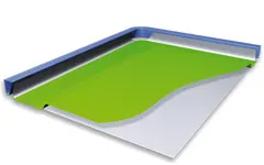
Fig:In conventional die hemming, the flange is folded over the entire length with a hemming tool.
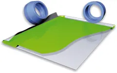
Fig:In roll hemming, the hemming roller is guided by an industrial robot to form the flange.
Conventional die hemming:
Conventional die hemming is suitable for mass production. In die hemming, the flange is folded over the entire length with a hemming tool. Normally the actual hemming is a result of a forming operation in which the flange is formed with a hemming tool after the drawing and trimming operations have been completed. The formed flange is then hemmed in several process steps. These steps include, for example, the pre-hemming and final hemming depending on the respective opening angle of the flange. Production plants for conventional die hemming are very expensive, but the cycle times are very low.
Roll hemming:
Roll hemming is carried out incrementally with a hemming roller. An industrial robot guides the hemming roller and forms the flange. Roll hemming operation can also be divided into several pre-hemming and final hemming process steps. Roll hemming is very flexible to use and tool costs are significantly lower as compared to those of conventional die hemming. However, the cycle times are much higher since the hemming is realized using a hemming roller which follows a defined path.
DESIGNING:
Hood Inner Panel Design:
For creating the hood inner panel first we required to consider the master data given and according to that we can offset the outer panel at the required distance and then joing that surface we can create the inner panel. we have to consider the embosses and cutting which is helpful for pedestrian saftey and also making the strength of the inner panel. After that we have to make the reinforcement for the hinge assembly and striker for attachment of that parts to the inner pannel.
The different views of the inner pannel is shown in below:
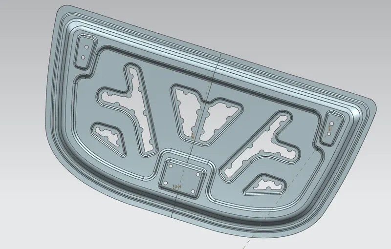
Fig: ISO-MATRIC VIEW
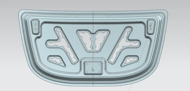
Fig: BACK VIEW(INSIDE VIEW)
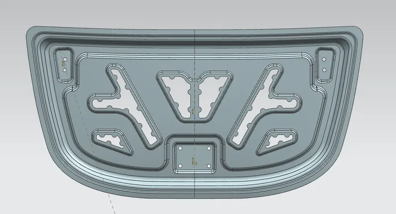
Fig: FRONT VIEW(OUTSIDE VIEW)
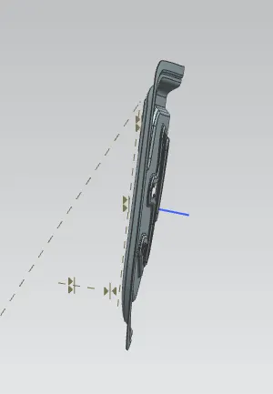
Fig: SIDE VIEW
OUTER PANEL DESIGN:
After completition of the inner panel model. We have to create the assembly and adding the inner pannel and the other all parts to the assembly. Now for creating the outeer panel we have to consider the given haming data and according to that we have to create the bend sheet as per the hamming data.
The different views of outer panel is shown in the below image.
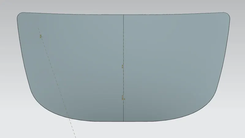
Fig: HOOD OUTER PANEL(FRONT SIDE)
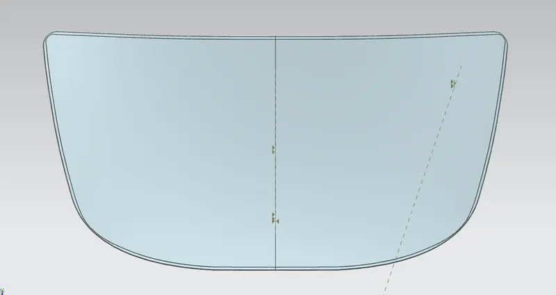
Fig: HOOD OUTER PANEL(BACK SIDE)
When designing the outer pannel we have to give the front and rear relief at the corner. because in during the hamming process for proper bending of the sheet we have to provide the proper relief at the corners.
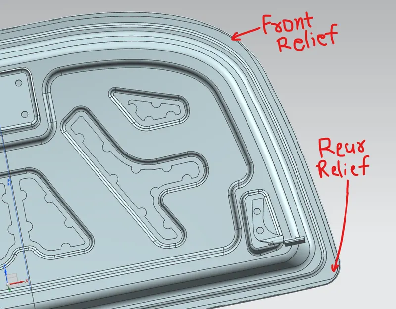
Fig: FRONT AND REAR RELIEF
HOOD ASSEMBLY DESIGN:
Now, after finish the both inner and outer panel we have to assemble the striker and hinge assembly at his place and also have to give the assembly constraints.
The different views of the hood assembly is shown in below image.
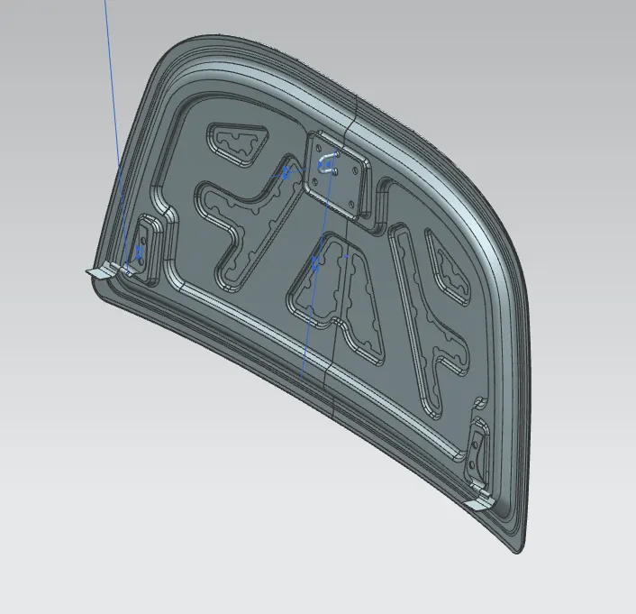
Fig: ISO VIEW
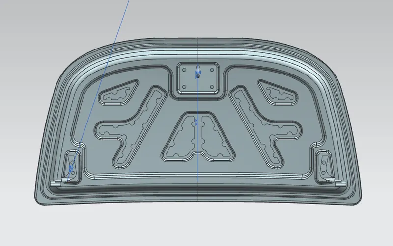
Fig: FRONT VIEW(INSIDE VIEW)
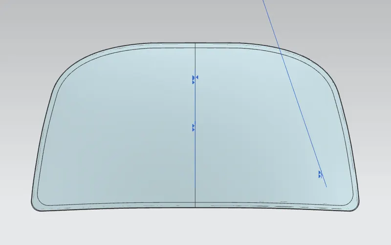
Fig: BACK VIEW(OUTSIDE VIEW)
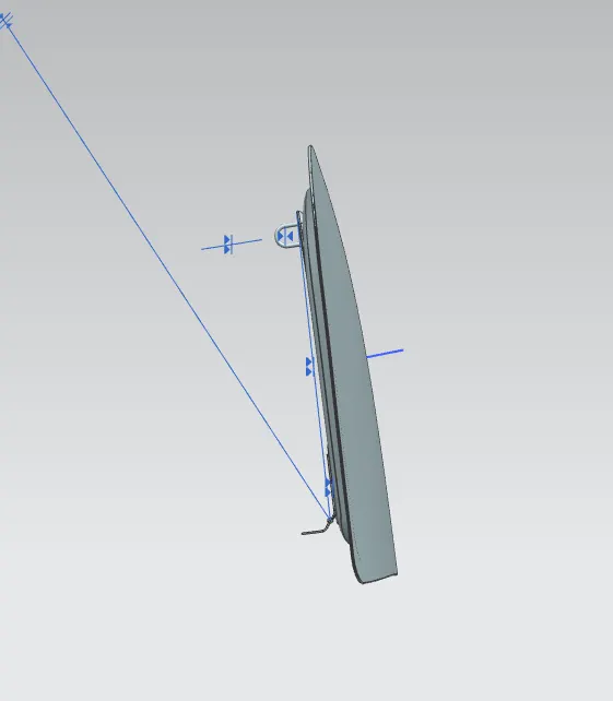
Fig: SIDE VIEW
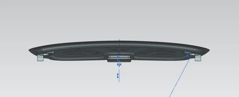
Fig: BACK VIEW
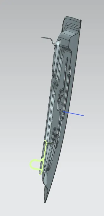
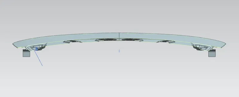
Fig: CROSS-SECTION VIEW
Latch:
A hood latch is basically the fastener which is used for keep the hood closed shut. This latch ensures that your hood is securely connected to your vehicle and that it doesn't pop open unexpectedly while driving the vehicle.
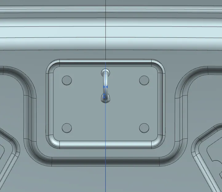
Fig: STRIKER FIXING
Hinge Assembly:
Hinge is a component that fixes the hood to the fenders of the car. The latch must be fixed perpendicular to the hinge axis so that the hood opens or closes properly.
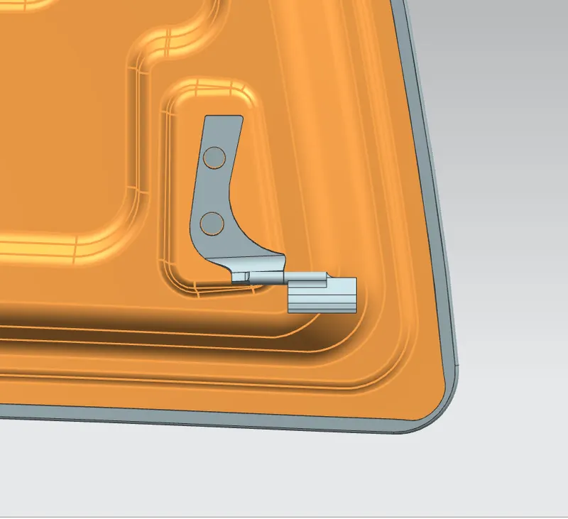
Fig: HINGE ASSEMBLY FIXING
Fig: REINFORCEMENT FOR HINGE AND STRIKER(EMBOSSING IN SHEET METAL)
Hinge Axis and Latch Trajectory:
When the opening and closing of the Hood is done the motion of the opening and closing at the hinge axis and due to the area of the opening and closing the latch trajectory is created at the center of the hinge axis. And the line where the latch is to be fixed is perpendicular to the hing axis and tengential to the latch trajoctory.
In the below figure the Hinge axis and latch trajectory is shown.
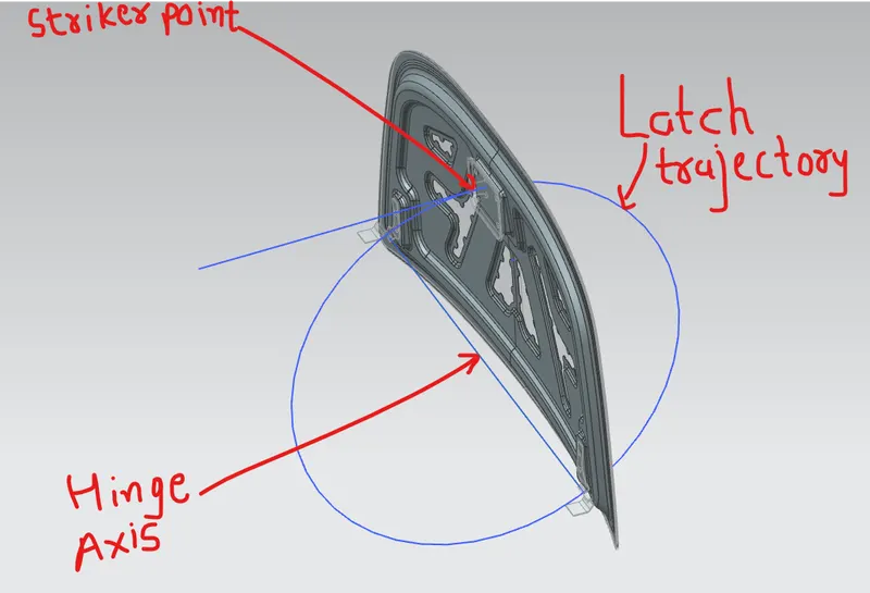
Fig: LATCH TRAJECTORY
DRAFT ANALYSIS:
I have done the 7 degrees of draft analysis to the inner panel to find any negative draft. Draft analysis is done because we must need to develop and submit a positive design to the manufacturers.
we can see that there are no negative drafts by the inner panel, hence the design is positive so, it can be manufactured without any difficulties.
In the below image the draft analysis is done in the siemens NX.
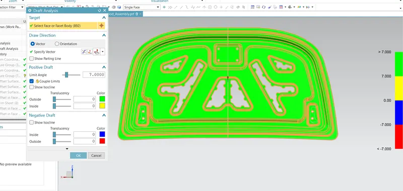
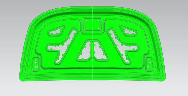
Fig: Draft Analysis
Conclusion:
With the completion of this design I have analysisng it using draft analysis tool and ensure that it have positive draft. Also considering the design specifications and allso safety standerds for the hood to the pedestrians. And I have conclude that the design can be utilized for successful manufacturabilty.