Wiring harness design in CATIA V5 - 3D modeling Week 2 Challenge
First of all we need to download igs or stp file for the all connectors give. for that we need to go to the website and in the document section there in the CAD files we can found the required igs or stp file and click on the link and download it. After downloading is complete unzip the file in the seperate folder.
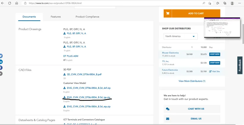
After that drag and drop the files in CATIA V5 software so the model of the connector is open.
Now here first the model is open in the part workbench.
and we required to define some geometry parameter of the model first in the part workbench.
First we need to define the Connector connection point and the bundle entry point. After that we need to define axis system for the connector connection point.
Also if there is a cavity attachment with the connector then we need to define cavity connection point also and the axis system for the same.
After this defining the all required parameter I have to go to the electrical part workbench.
Then in the electrical part workbench first I have to define the connector. So click on the define connector icon and select the connector.
In case of connector clip we have to define the clip as support part.
After defining the connector or support part we have to define the connector connection point,bundle connection point and cavity connection point. In case of clip we have already define cavity connection point in the connector so we have to define the clip as cavity.
and save the models.
After All the electrical parameter defines I am create new product in the electrical assembly workbench. and add the part connector and clip in that. After adding click on the connect electrical device and select the clip first and then click the connector and the assembly is done.
1)first drag and drop the model C-DT06-08SA in CATIA V5 and open the model.
After that ensuring that it is in the part workbench.
Now for first we are create the connector connection point . For that click on the point and select the face which is connected to the male connector. and create a point in the middle of the face by using the face geometry.
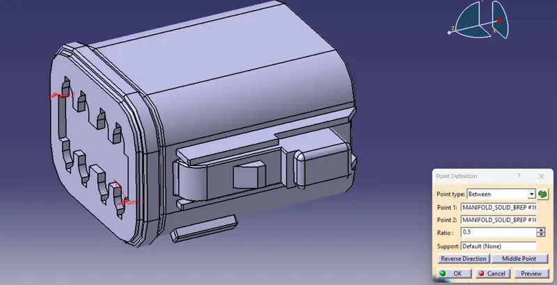
After click on OK button we have found the point on the surface of the connector and I am rename the point as connector connection point.
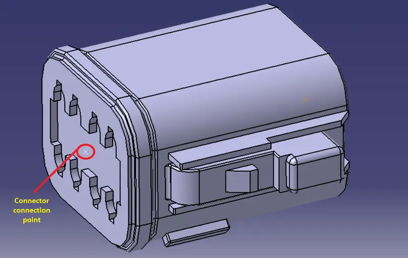
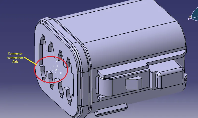
After getting connector connection point we need to define the connector connection axis. For defining the axis click on the axis system and put the Y-axis in the direction towards the connector and the X-Axis is towards the locking mechanism. After that click on ok.
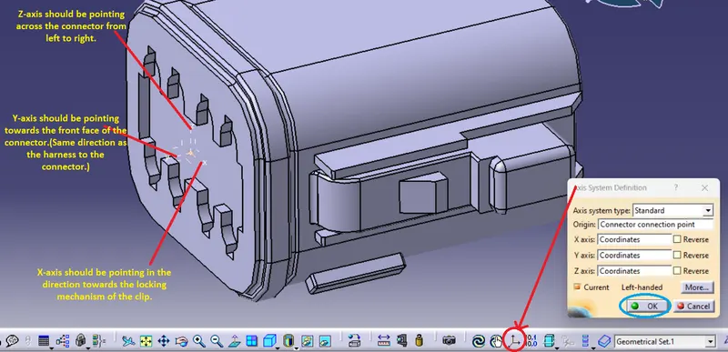
After click on ok axis should be defined as per below image.
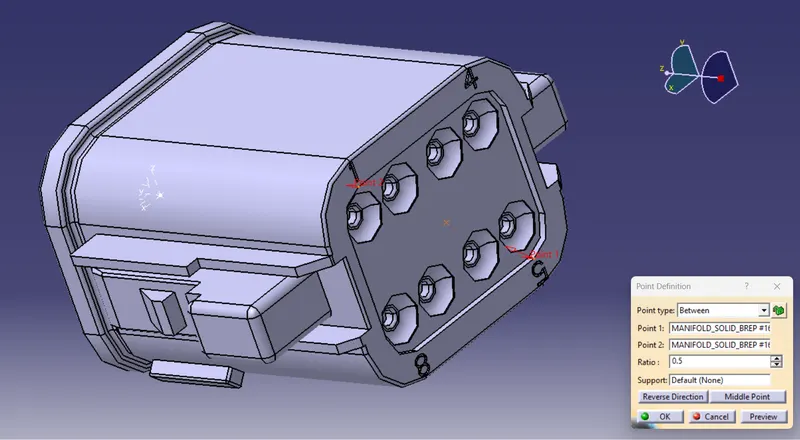
Now defining the bundle entry point. for that same as taking a point on the end face of the connector from where the bundle entry is done. As per below image give the input and click ok.
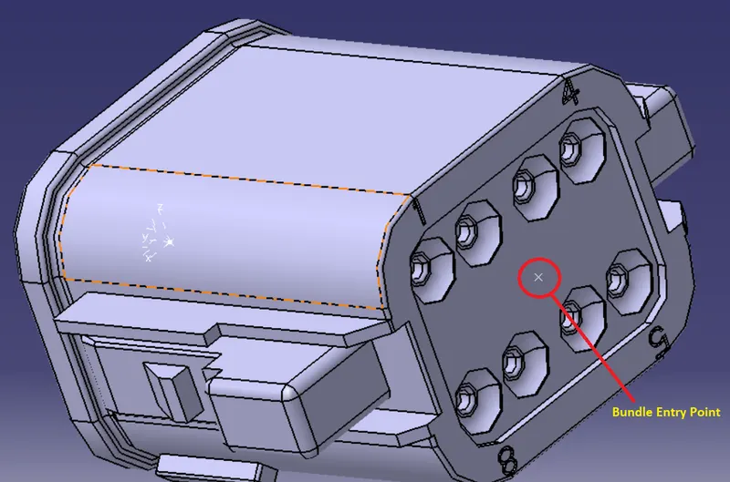
The bundle entry point is created as per below image and renaming it.
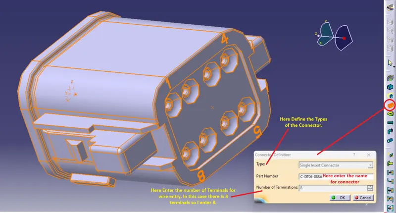
Now all required geometry parameter is define. Now go to the electrical part workbench and we need to define the connector as electric part. For that click on the define connector command and select the connector. give the name of the connector and give the number of terminal entry and then click on ok as per below image.
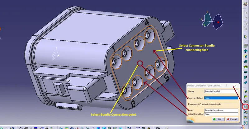
After defining the connector as electric part we need to define the parameter of the connector in the electtric part workbench. So, first I am defining the bundle entry of the connector. Click on the icon as shown in the below image and give the input as per the below image and after that click on ok button.
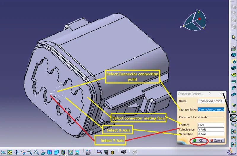
Same as we have to define the connector connection poin for that we have to select the coinsidence axis as the Y -axis and orientaion as X-axis as per the below image give the input and click on ok.
After click on ok button the all required parameter is defined and click on the save button and save the connector.
2)Same procedure is done for the second connector. Here in the second connector there is locking mechanism is given and for that we have to provide the cavity connection point.
So, First of as per the above explained steps I define the all points.
And give the all image in the below.
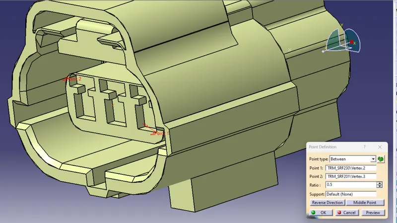
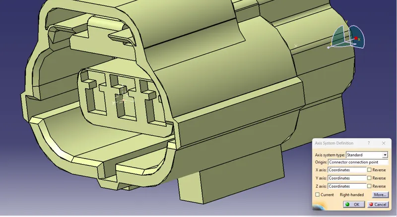
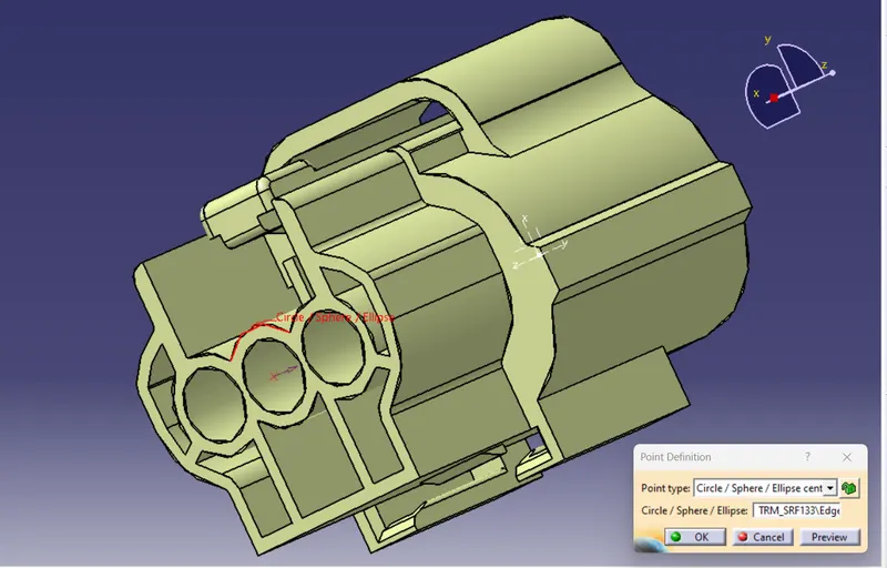
Here , In addition there is cavity connection point needs to be define for the connector as per the below image.
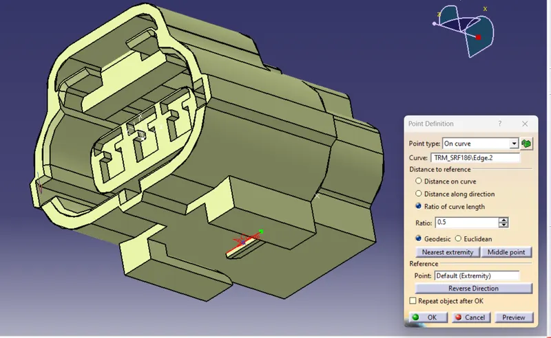
Also There is axis system is defined for the cavity connection point. Here the direction of the axis system is same as per the connector connection axis system.
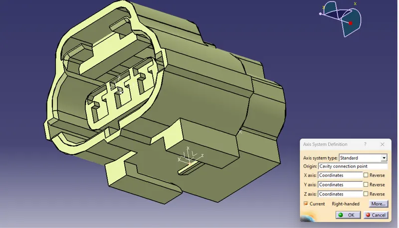
After this geomatrical parameter define we are move the connector to the electrical part workbench.
Here first we define the model as connector and then as per the previousally explained steps same as all steps to be followed and I have attach the screenshot in the below image.
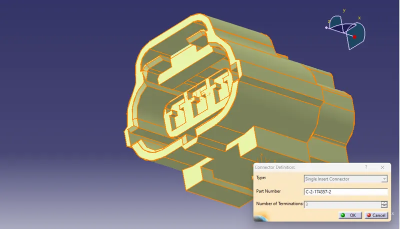
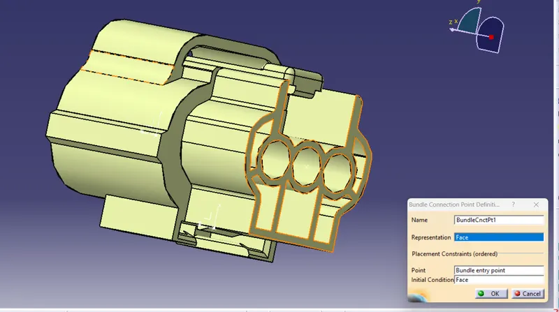
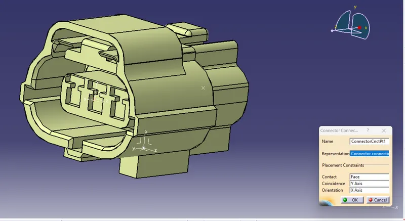
For defining the cavity connection point we need to click on the icon and the dialouge box open in that give the inputs as per below image and then click on ok.
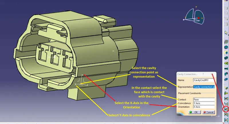
After click on OK all the required parameter is defined for the connector so save the connector.
3)In this third model the connector clip is given. So for the clip we have to define the point of the connection and axis system.
So I am defining the connection point and axis system for the clip as per the steps describe on the above.
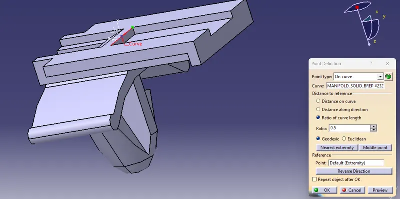
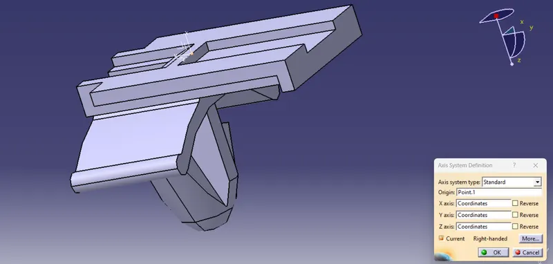
Now go to the electrical part workbench and click on the defining mounting part icon and select clip and click ok. So clip is defind as a mounting part.
Now for the clip we don't neet to define any connection because we are already define the cavity point in the connector.
So, Clip is defined as Cavity. Click on the define cavity command and follow the input as per the below image and click ok .
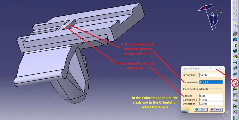
After click on ok button. All the required parameter is defined for the clip so save the model.
For Assembly:
First click on new and select the product and click on ok button.
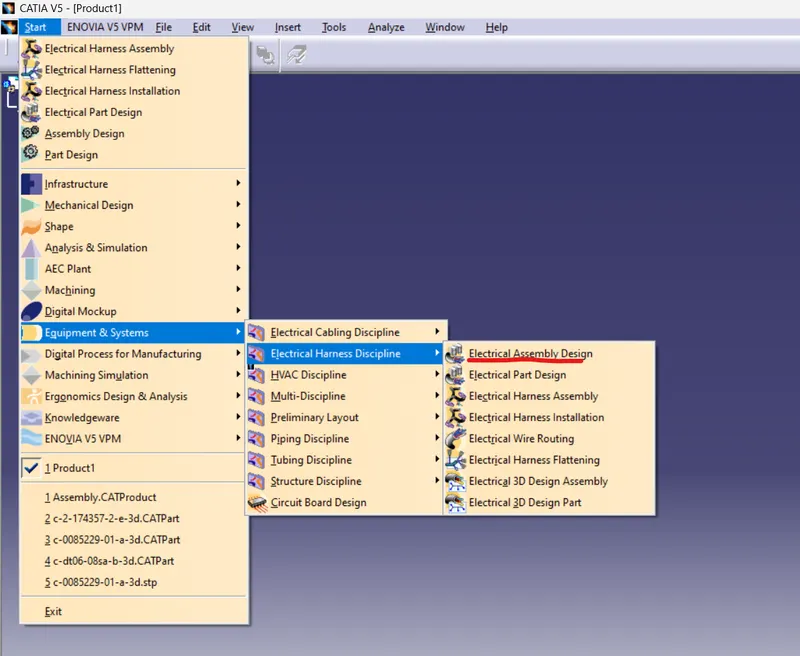
Then Go to start and from that go to equipment and system-->Electric harness displine-->electrical assembly design.
Now go to the exiting componenet command and click on that and then click on the product and the window open from that select the bothe connector and clip and click open.
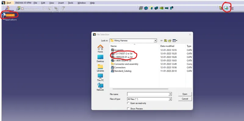
Or we can copy paste the part in the product.
Now when click on open the part is added to the assembly workbench as per below.
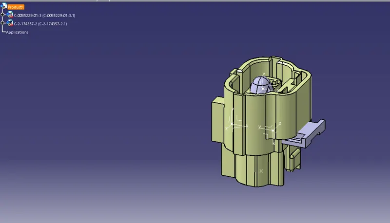
Now rearranging the part as per required direction and after that click on the connect electric device command.as per below image. and select the clip first and then select the connect the clip is assemble with the connector with the constraint.
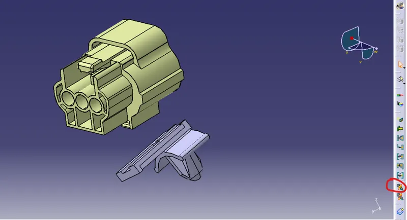
When click on the connect electric device and first select the clip then the connect automatically shown the required position for the clip in the green point. as per the below image.
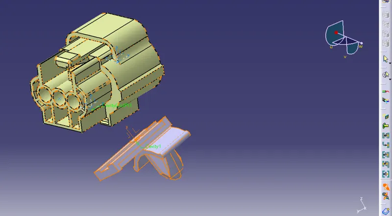
When selecting connector the aseembly is done with the constrain.
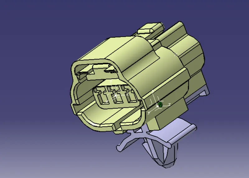
Save the assembly.