Week 9 - Attachment Feature Creation - Challenge 2
AIM:
Create the boss and Dog House for the Centre console coin holder considering the design rules.
OBJECTIVES:
Create Class B and C surfaces through given Class A surface. also Create tooling axis using bisecting method. and Perform draft analysis for the class A surface and part body. Create screw boss and dog house considering the design rules.
TOOLING AXIS:
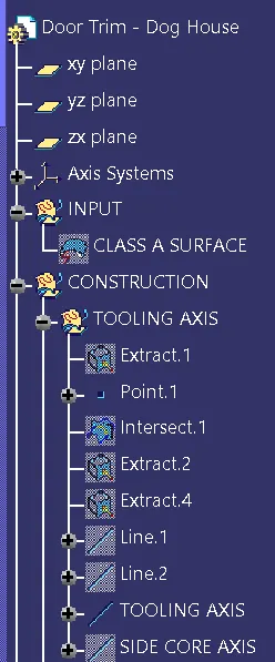
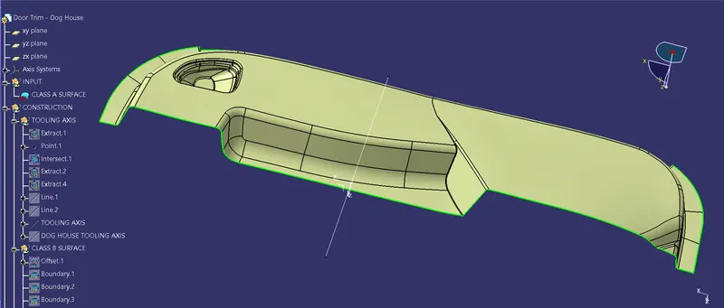
To create the tooling axis initially, I extracted the surface of class A with no propagation and I created the point at the centre of the extracted surface and taken intersection of the class A surface. Now I extracted the two lines from intersection and then taken a bisecting line of them. And the bisecting line which i have created is the tooling axis of the surface.After creating the Tooling axis, I performed a draft analysis for class A to check the draft angle for it.
CLASS A SURFACE AND TOOLING AXIS:
DRAFT ANALYSIS:
Draft analysis helps to detect if your drafted part is easily removable from the mold (in case of plastic component) or die (in case of sheet metal). All plastic components will have a minimum draft of 0.5 to 3deg. And for automotive sheet metal parts the draft will be 7deg or more. If a mold wall is perpendicular to the part ejection, there is ample friction or interference between the mold and the part which will not allow one to release from the other. This is why design engineers give a minimum draft to the part.
DRAFT ANALYSIS FOR CLASS A SURFACE:
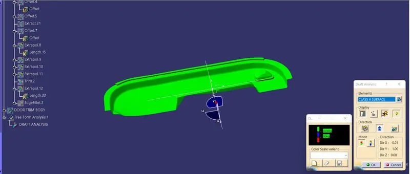
To perform the draft analysis in class A, I selected the featured draft analysis tool in the Generative shape design workbench. Initially, I align the compass to the tooling axis. Once the compass is aligned to the tooling axis, we need to select the surface which we need to perform a draft analysis. Class A surface will be highlighted according to the colour bar angle and colours we defined in it. If I gave a 3deg draft angle some faces are not getting cleared, so I have gradually reduced the draft angle to up to every face gets cleared.
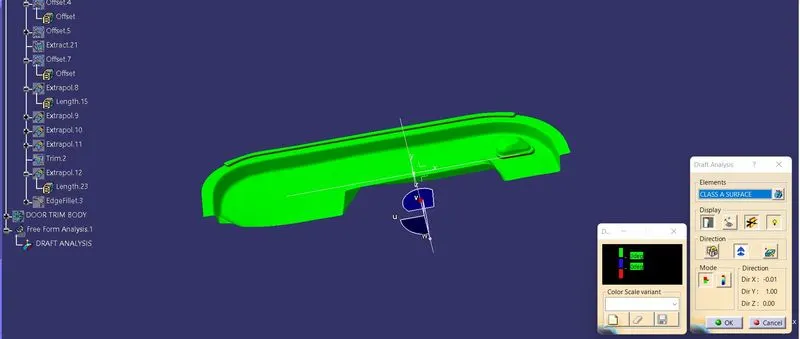
Some faces in the class are not get cleared with a 3deg draft angle, even if we give less than a 1deg draft angle. This happened because the faces which are not clearing with less than one degree also are not drafted properly while creating a class A surface.
CLASS B SURFACE:
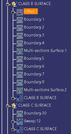
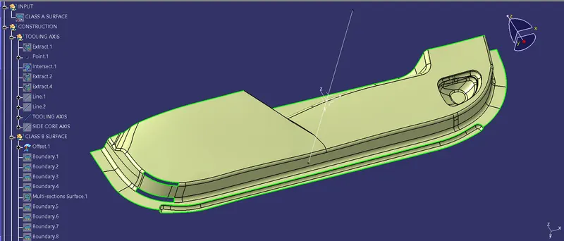
To create the class B surface for the door trim, First I offset the class A surface to 2.5mm inside. Once the class A surface offset is created according to the thickness, we can observe some patches on the offset surface due to the fillets on the class A surface. Now, we need to close those patches. I used multi-section solid command to close the patches.
Class A offset:
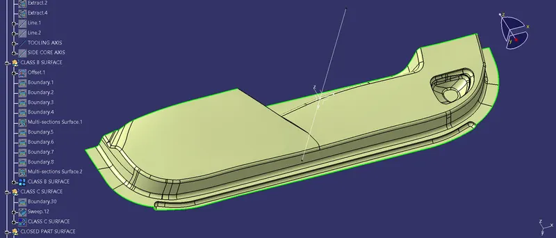
I used a multi-section solid command to close the patch to create the proper 'Class B surface'.
Class B surface:
CLASS C SURFACE:
I used the sweep command in the geometric shape design workbench to create the class C surface. Initially, I create the boundry of the class A surface. I sweeped the boundry with 93deg toward the class B surface. And final class C surface is to be done.
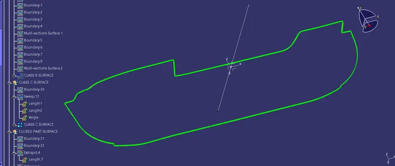
FINAL CLOSED PART SURFACE:
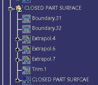
For creating the closed surface for the part first I create the extrapolation of the class B surface and then triming that to the class C surface. After that I am going to join that trim to the class A surface. And this way the closed part surface is to be done. before this we confirming about the close surface we an check it by using the boundry command.
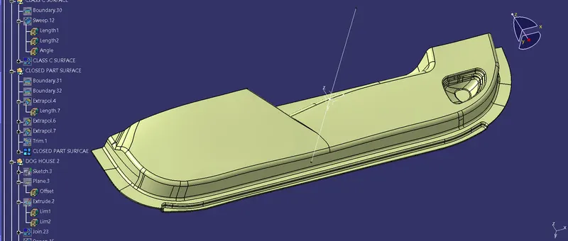
CLOSED PART BODY:
For creating the closed body first we need to go to the part modeling workbench and then the seleccting the closed boundry we can convert it to the part model shown like the below image.
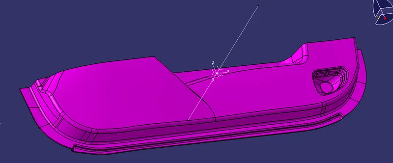
DOG HOUSE DESIGN:
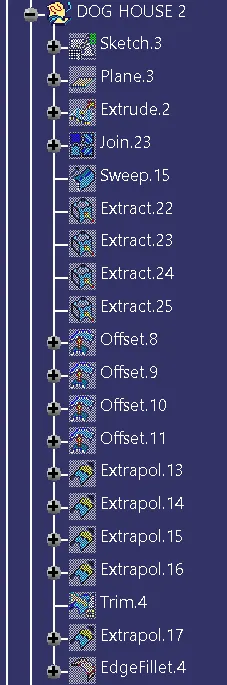
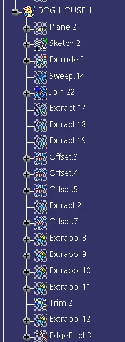
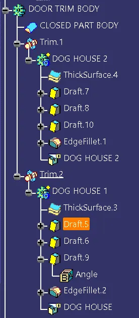
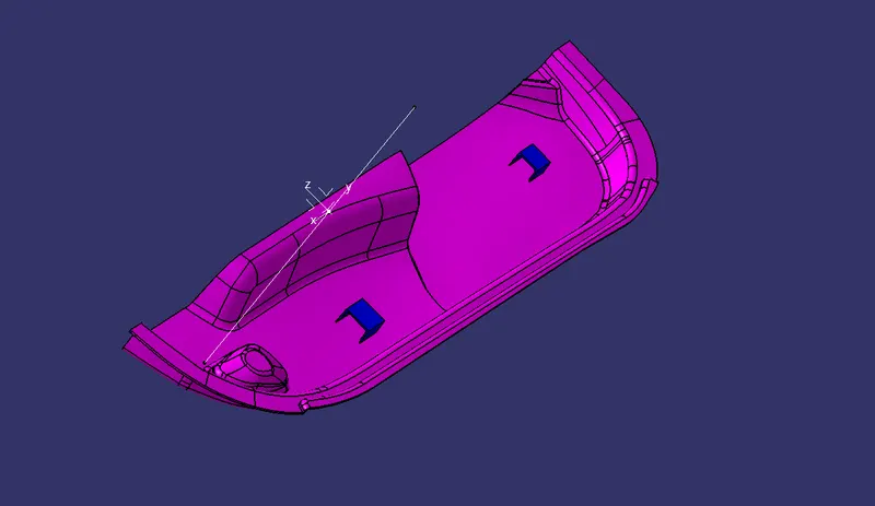
To design the dog house, I created a sketch for the dog house. Initially, I created a plane on the surface of class B at the 'point.1'. After drawing the sketch, I Extrude the sketch 20mm upward direction and 1mm downward direction with a 1.5deg draft angle and I thicken the surface outward direction by 2mm. Now we need to design the bottom connection of the dog house. To design the bottom connection of the dog house, I sweep the inner surface edges. now take the extract of the upper surface and offset it to the downward direction for 13mm to trim with the 1mm offset surface. Now split the solid with the help of the trimmed surface, by using the split command in the part workbench.
Now I gave a draft angle of 0.5 deg for the split surface. The inner split surface is 0.5mm, the inner surface fillet is 1mm and the outer surface fillet is 3mm (inner fillet 1mm + thickness 2mm = outer fillet 3mm).
Dog house Sketch:
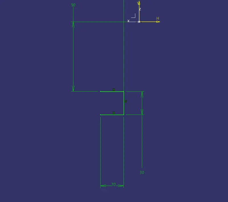
Solid Part Body including Dog House:
Draft analysis for the solid part body:
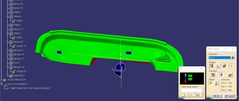
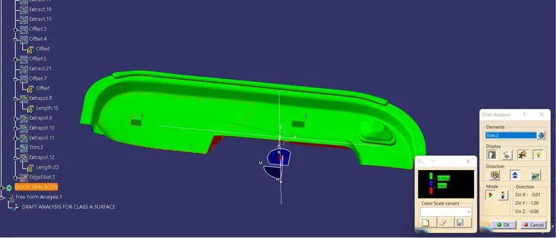
To perform the draft analysis for the solid part body (which has Dog Houses on it), I used the featured draft analysis tool in the generative shape design workbench. Initially, I aligned the compass to the tooling axis and I selected the solid part body, I gave a 3deg draft angle in the colour bar. Even if I gave less than a 2deg draft angle in the colour bar some faces are not clearing properly, due to the class A surface draft angle and curvatures on it. the solid body has shown in red and blue colours even though we gave 0.9 deg in the draft angle in the colour bar we can't decrease the draft angle to less than 0.5deg because the draft angle for the plastic component is 0.5deg to 3deg).
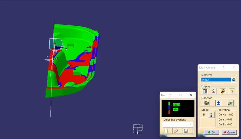
Initially, we need to check the draft analysis concerning the tooling axis and then concerning the side core axis.
3deg draft angle by using Tooling Axis:
0.4deg draft angle by using Tooling Axis:
Side core Axis:
In the colour bar, I gave 0.48 deg for green because the sweep angle is 0.5 deg for the outer surface.
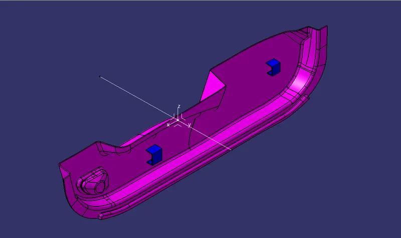
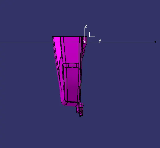
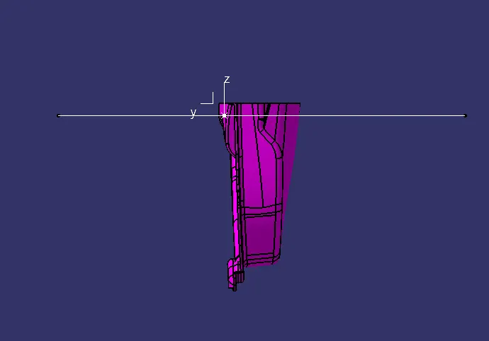
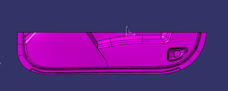
Different Views of solid part model:
ISO View:
FRONT View:
BACK View:
LEFT Side View:
RIGHT Side View:
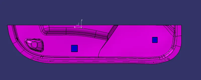
TOP View:

BOTTOM View:
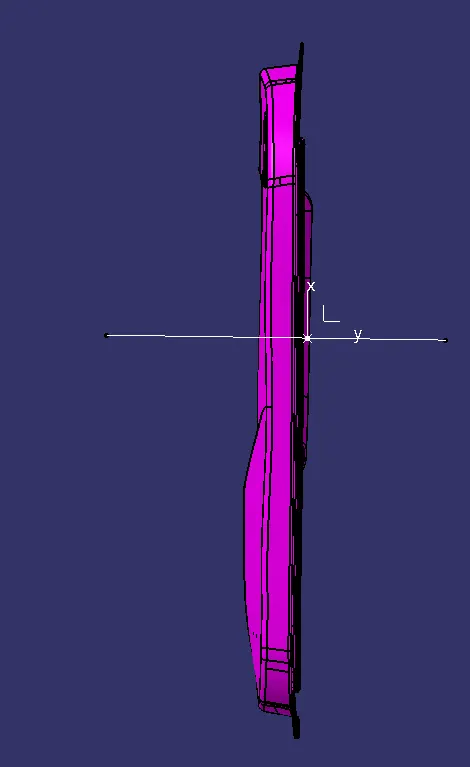
TREE STRUCTURE: