Week 8 - Challenge 4 - Bumper
OBJECTIVE:
To design Bumper with respect to the given class A surface. Create class B surface and class C surface and the tooling Axis for the same. Convert those sub-surfaces into a close body and make it into the solid body for that provide the thickness of 3 mm.
Performing draft analysis to verify the creation of tooling axis and class C surface.
CLASS A SURAFCE:
First open the given class A surface and then define the faces of the surfaces. First of all we done the draft analysis for the class A surface for that we required the tooling axis.
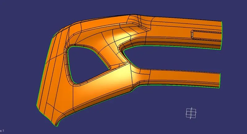
Tooling Axis:
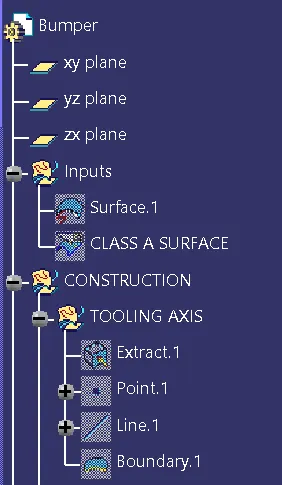
For creating the tooling axis first of all need to extrapolate the base surface of the class A. and than take the point on the surface. After that create the line which is passing from surface and perpendicular to the surface.
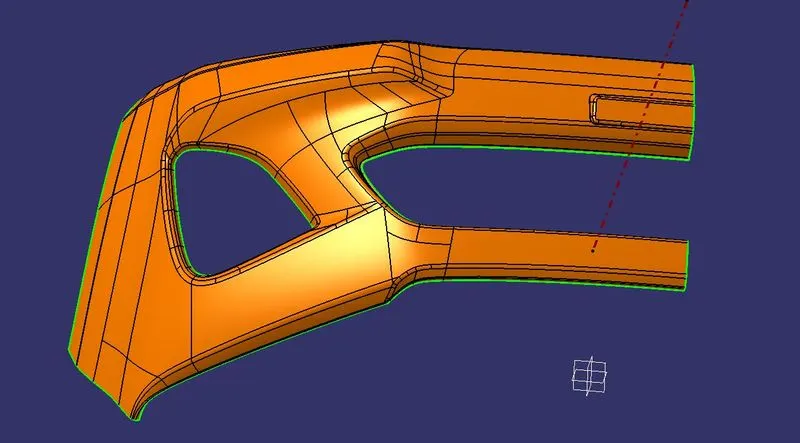
The perpendicular to surface line is our tooling Axis.
Draft Analysis for Surface A:
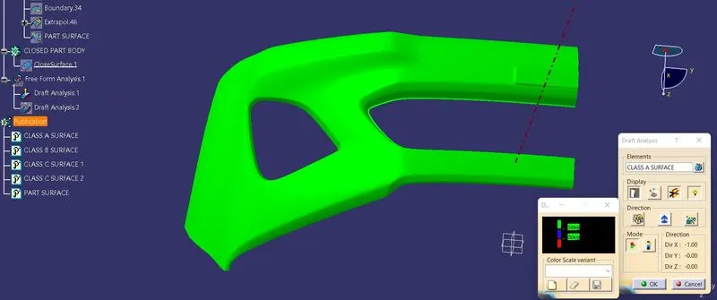
Now using this tooling axis we done the draft analysis of the surface A . For that we need to select the insert and from that select the analysis and then select the draft analysis. for done the analysis first we have to select the material mode. Now select the surface for draft analysis. set the axis system to the inline to the center of the tooling axis and than lock it. The selected color is as per the given figure.
CLASS B SURFACE:
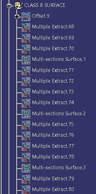
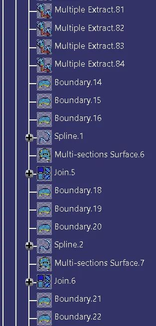
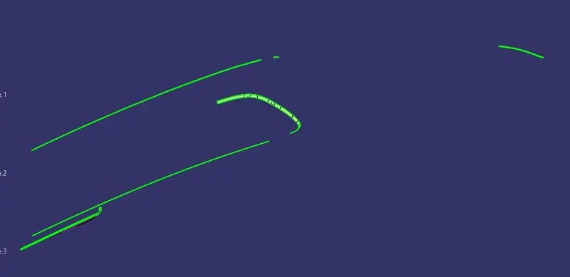
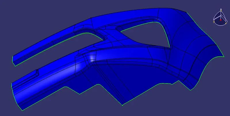
For creating the class B surface first offset the class A surface to 3.00 mm in the below of the class A surface. After that there are some manifold are observed. Fill them using the multiple extract command and the sweep command. Also we can use the multiple sweep option by taking the different edges of the manifold. After recreating all the manifold surface we must need to join tthem all using join command. We must ensure that there is no any gap will be remaining in the creation of class B surface for verfying this we take the boundry command and check that.
Now, In the below figure the steps of creating class B surface is shown.
first offset the class A surface to 3mm below.
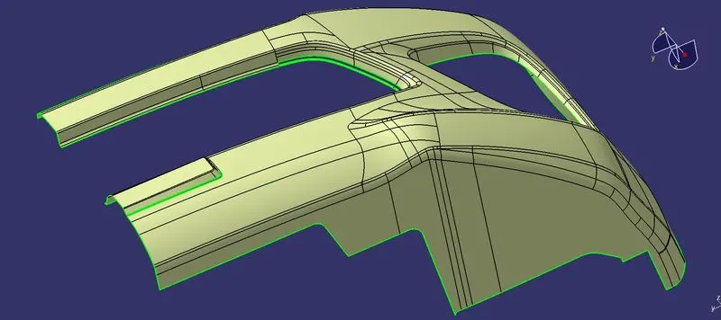
Now recreating surface of the manifold.
JOINING OF CLASS B:
CLASS C SURFACE:
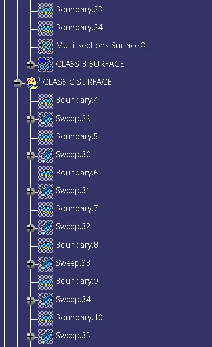
First get the boundary lines of class A surface separately. for that we have to Smooth curve with smooth option as boundary line have a lot of vertices. Now, Sweep curve with toolling Axis as direction in Swept option we can take the direction with surfaces first select the boundary and then select the surface of the class A as reference surfaces.
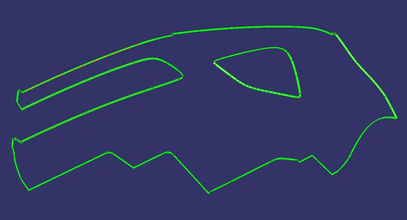
Now join the class C surface to the class A surface.
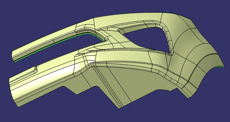
JOINING OF CLASS A, B ,C SURFACE:
CLOSED SURFACE:
For create the close surface first join the class A and class C surface and then trim it with the class B surface so as an output we get the desired close surface of the part. for trimming the class B syrface to class C surface first we need to extrapolate whole boundry to the 1mm so we can trim it from the class C.
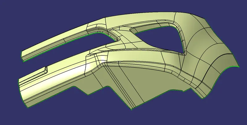
And after extrapolating trim it with join of class A&C.
So, we get the closed surface as below.
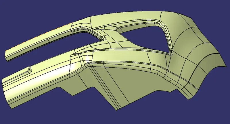
CLOSED BODY:
For closing the body first ensure that the surface is closed for that we use the boundry command and select the surface so we can confirm that the surface is fully closed. After that go to the part body workshope and then select the option of the closed surface.
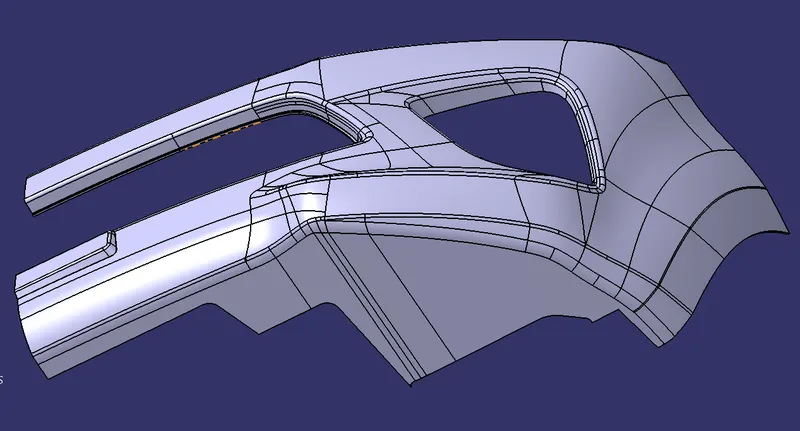
APPLYING DRAFT ANALYSIS:
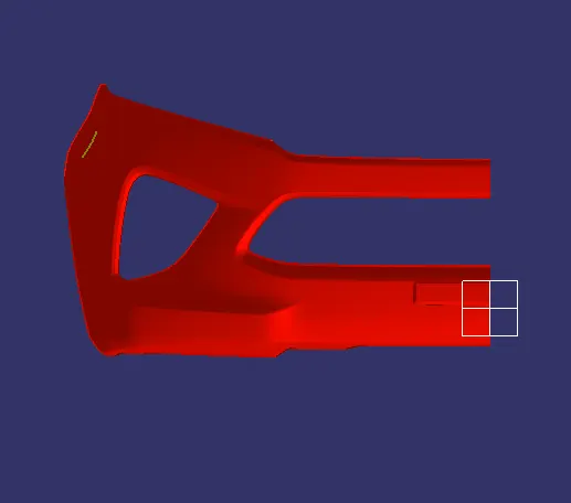
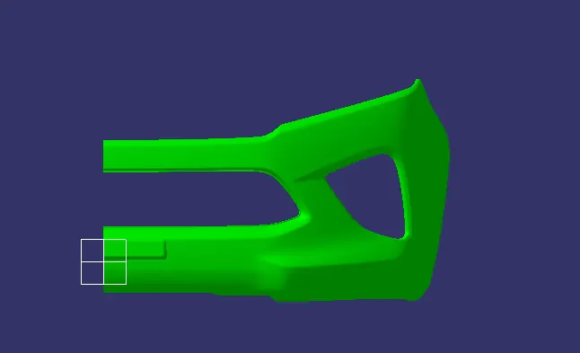
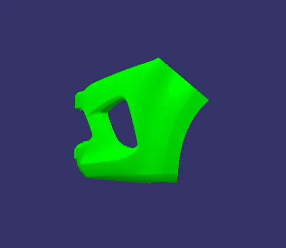
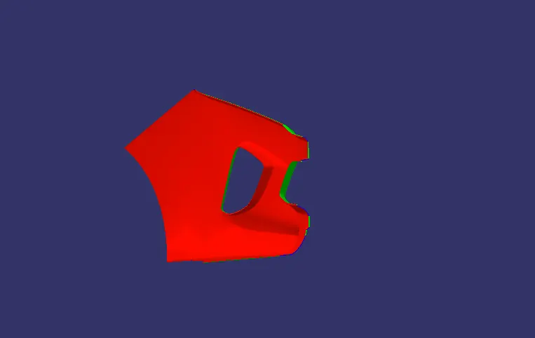
Go to the material mode and then go to select the draft analysis option.
Here first set the axis to the inclined of the tooling axis and then select the part body . lock the axis system.
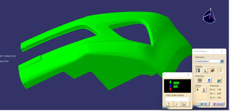
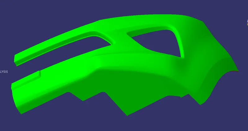
DRAFT ANALYSIS
ISO VIEW OF DRAFT ANALYSIS:
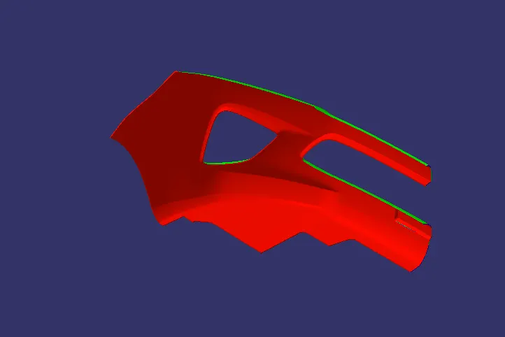
FRONT VIEW OF DRAFT ANALYSIS:
BACK VIEW OF DRAFT ANALYSIS:
LEFT SIDE VIEW OF DRAFT ANALYSIS:
RIGHT SIDE VIEW OF DRAFT ANALYSIS:
TOP VIEW OF DRAFT ANALYSIS:
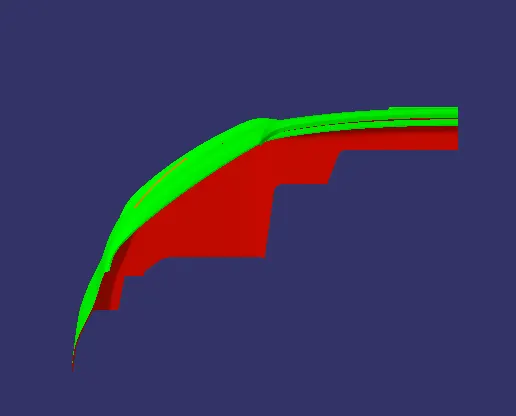
BOTTOM VIEW OF DRAFT ANALYSIS:
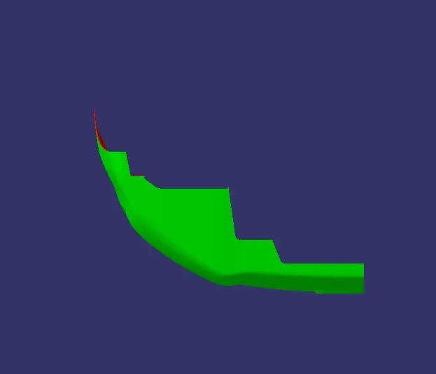
PART MODEL DIFFERENT VIEWS:
ISO VIEW:
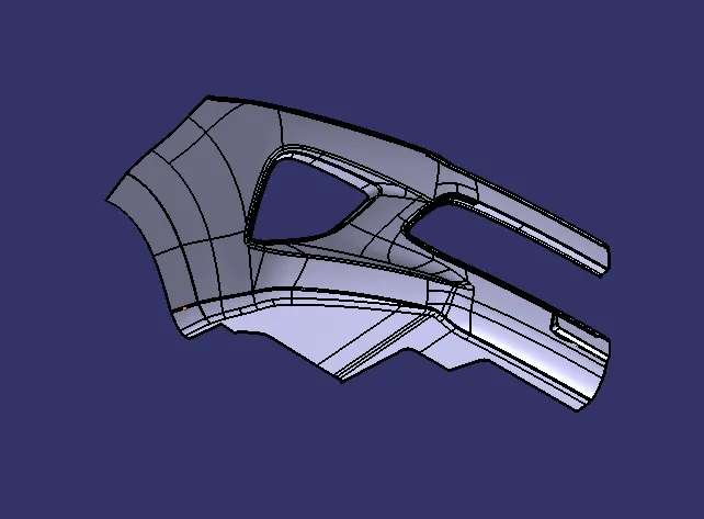
FRONT VIEW:
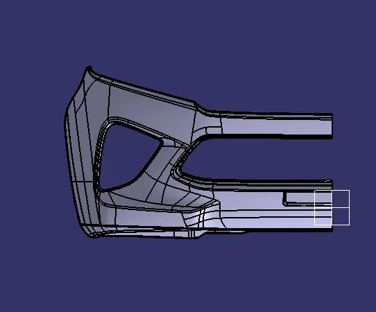
BACK VIEW:
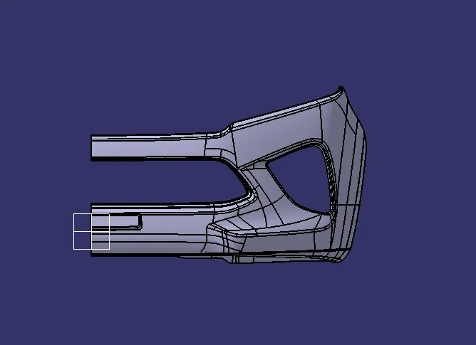
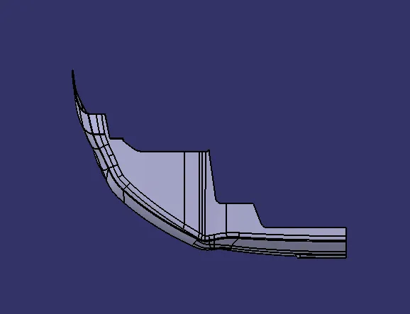
RIGHT SIDE VIEW:
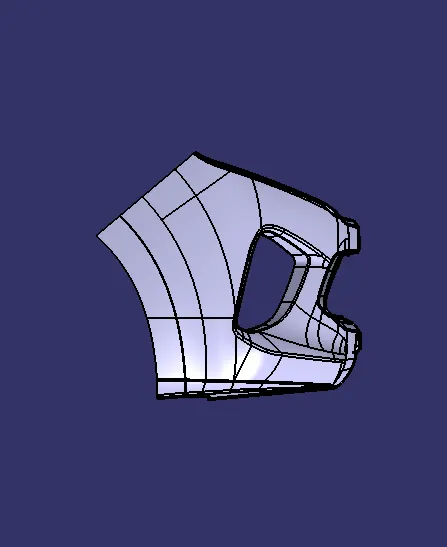
LEFT SIDE VIEW:
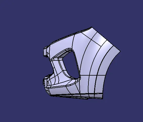
TOP VIEW:
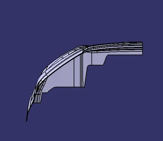
BOTTOM VIEW:
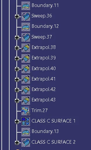
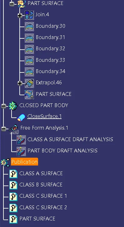
TREE STRUCTURE: