Wiring harness design in CATIA V5 - 3D modeling Week 4 Challenge
First I have go to the website www.te.com and search the all given connector and download the igs files of the all given connectors.
- DT06-4S
- DT06-6S
- DT06-2S
- DT06-08SA
After that I have extract all files one by one and open in the CATIA V5.
Now I am defining all connectors as electrical part for that I am defineing geometrical parameter in the part workbench and then go to the electrical part workbench and define the part as connector and defining the electrical parameter and then save the part file. I have explain one connector steps for the defining as electrical part.and follow this steps for all other connector and then save them as electrical part.
1)first drag and drop the model C-DT06-08SA in CATIA V5 and open the model.
After that ensuring that it is in the part workbench.
Now for first we are create the connector connection point . For that click on the point and select the face which is connected to the male connector. and create a point in the middle of the face by using the face geometry.
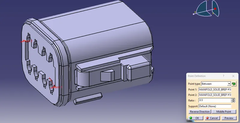
After click on OK button we have found the point on the surface of the connector and I am rename the point as connector connection point.
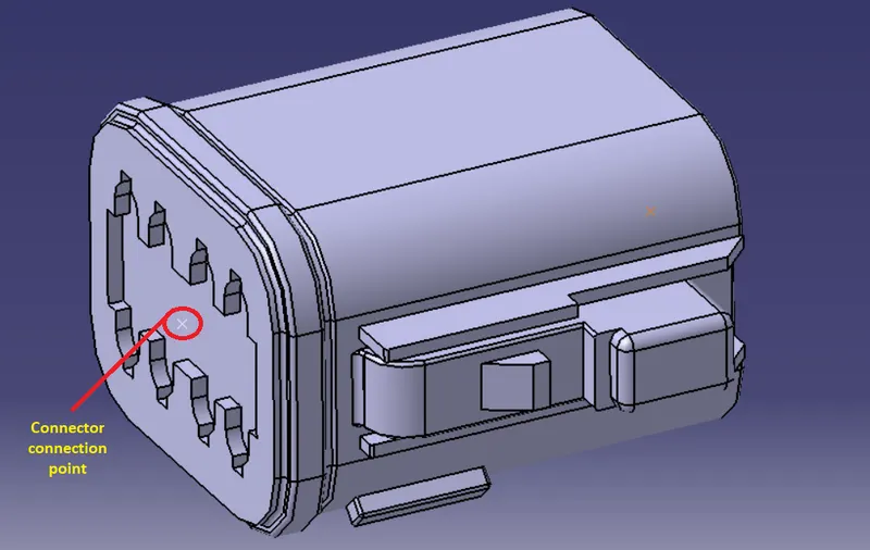
After getting connector connection point we need to define the connector connection axis. For defining the axis click on the axis system and put the Y-axis in the direction towards the connector and the X-Axis is towards the locking mechanism. After that click on ok.
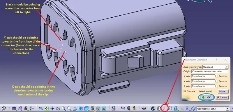
After click on ok axis should be defined as per below image.
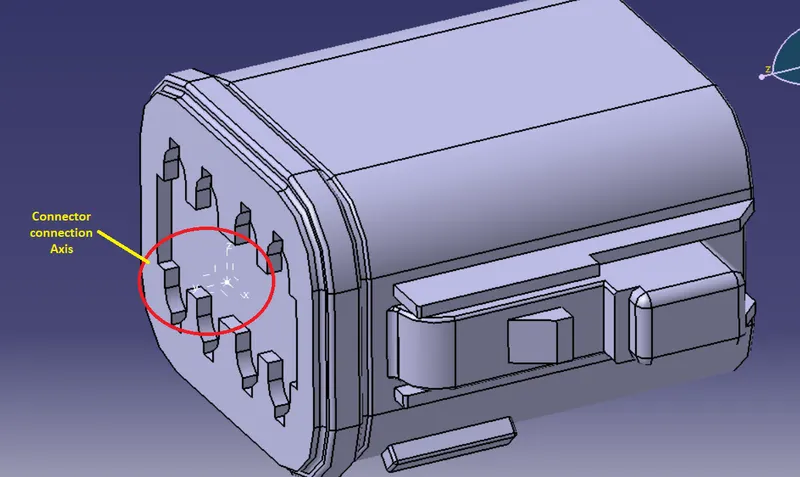
Now defining the bundle entry point. for that same as taking a point on the end face of the connector from where the bundle entry is done. As per below image give the input and click ok.
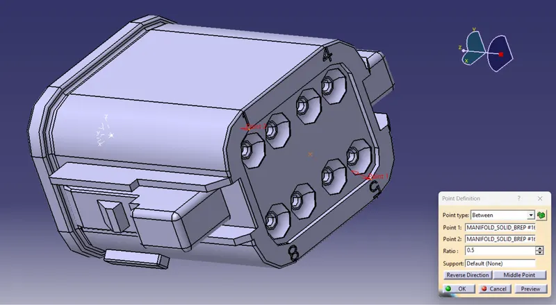
The bundle entry point is created as per below image and renaming it.
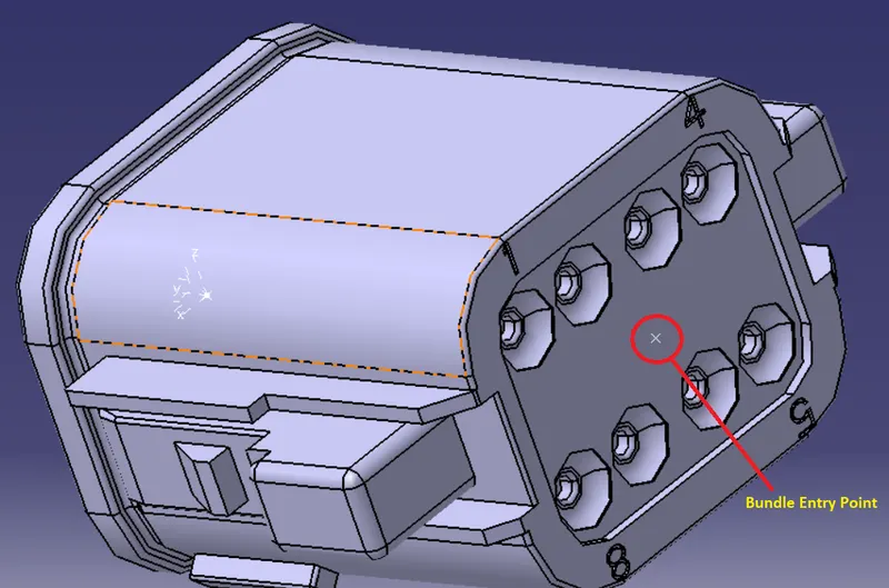
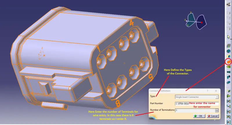
Now all required geometry parameter is define. Now go to the electrical part workbench and we need to define the connector as electric part. For that click on the define connector command and select the connector. give the name of the connector and give the number of terminal entry and then click on ok as per below image.
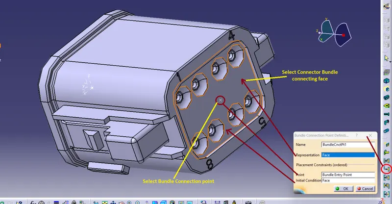
After defining the connector as electric part we need to define the parameter of the connector in the electtric part workbench. So, first I am defining the bundle entry of the connector. Click on the icon as shown in the below image and give the input as per the below image and after that click on ok button.
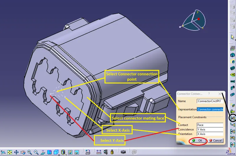
Same as we have to define the connector connection poin for that we have to select the coinsidence axis as the Y -axis and orientaion as X-axis as per the below image give the input and click on ok.
After click on ok button the all required parameter is defined and click on the save button and save the connector.
Now following above steps for other all connectors and save them seperately.
Create a catalouge for the connectors and add all connectors to the catalouge.
Now create the new product file in the assembly design workbench and give the name to this product as "Assembly_wiring_harness_contex". which is the main assembly of the product.
Now right click on the Assembly product in the tree structure and go to the components and click on new product.
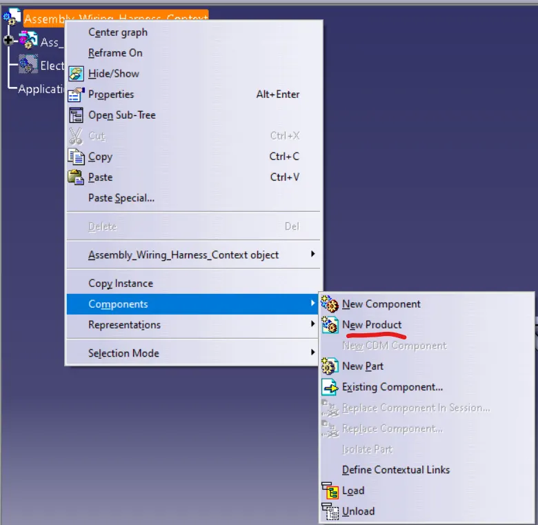
Rename this as "Ass_geometrical_Bundle" and again go to the same process and add one more product and name it as "Electrical_Bundle_Circuit".
The Harness Context Assembly: this is the top level product file that contains the harness Geometrical bundle/Assembly and the wire harness electrical bundle.
Geometrical Bundle: This sublevel product file is the wire harness product that contains all of the harness components i.e. clips, supports, connectors, splices, grommets, annotation and actual physical bundle segments and branches.
Electrical Bundle: This sublevel product file contains all of the electrical circuit information.
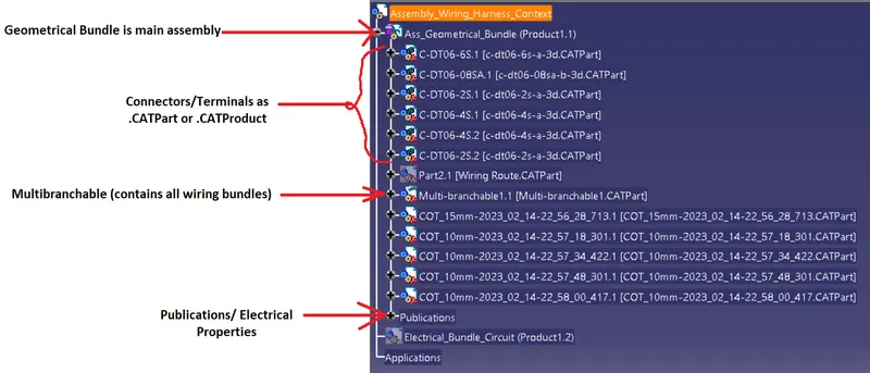
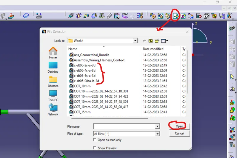
Now open the "Ass_Geometrical_Bundle" in new tab. here, I am in assembly part workbench first. Now for adding the connectors we need to add the connectors by clicking on "Existing Compononet" icon and then select the product name from tree structure and then select the all connectors which I want to add in the assembly and click on open.
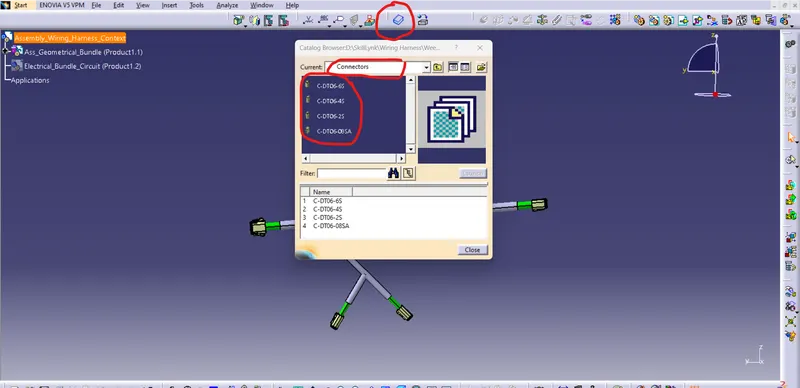
Or I can add all connector by using the catalouge browser option . For that I am selecting on the catalouge browser icon and the selecting the catalouge where the connectors are save and then add connectors one by one from that catalouge. Shown in below image.
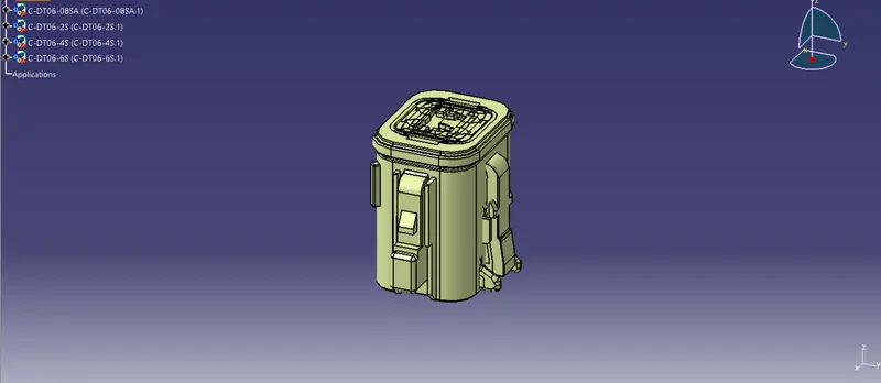
Now, all connectors are added to the assembly part workbench as per below shown image. and aftere that go to the electrical harness assembly workbench.
Click on the "Geometrical Bundle" Icon as shown in below image. and then click on the product name in tree structure.
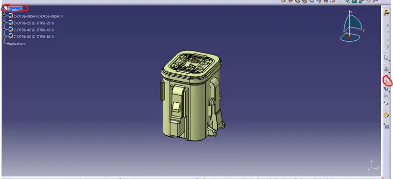
The Assembly is converted in to electrical assembly and the publication is added in the tree structure.
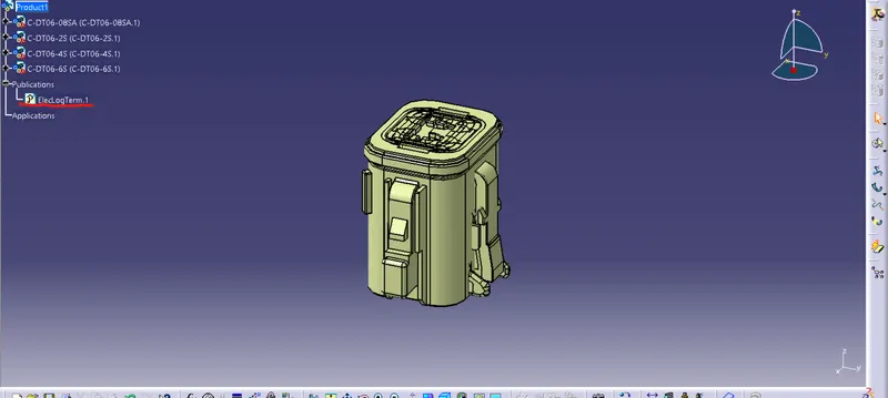
Now , We need to reaarange the Connector position as per the given wiring harness bundle.
So, For that I am creating new part file in the assembly.
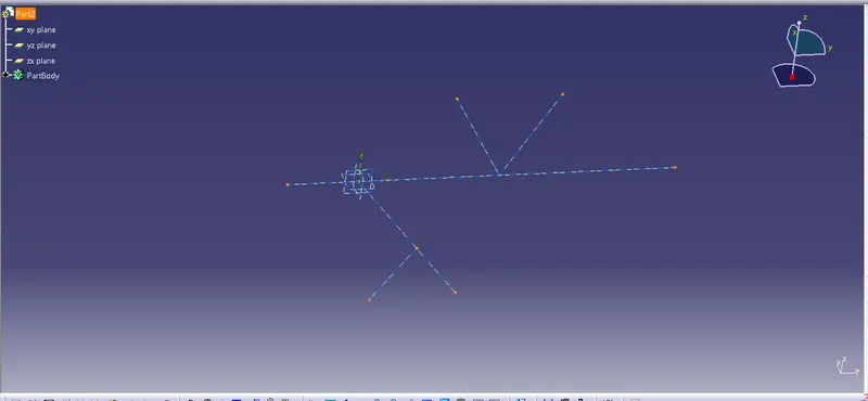
In this part file I am create a sketch for the given wiring harness route. shown in below image.
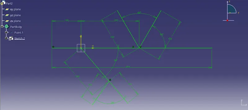
After Finish the sketch. Arrange all required connector to the end point of all Branch which is given in above image.
For rearranging the connector I am use Compass. For using compass moving the object first of all drag the compass to the object and then select the object and select the axis or direction where to move the connector. In this way First I am moving all connector to the nearest point and set them to the nearest position.
After this I am use the snap command and select the bundle entry point and then select the end point of the branch. So the connect are set to that point. and for setting the axis inline using the snap command first selecting the center axis of the connector and then selecting the line of the branch where the connector are need to rearrange.
In this way first of all I am rearranging the connector which is shown in below image.
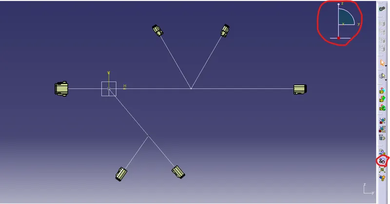
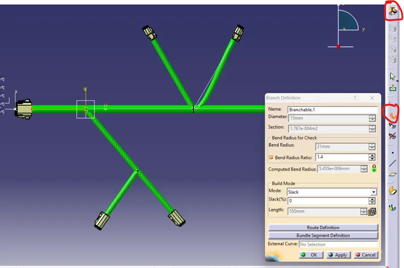
Now go to the electrical harness assembly wizard and click on branch definition icon as shown in below image.
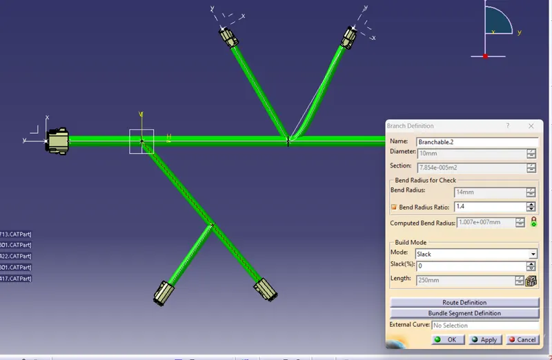
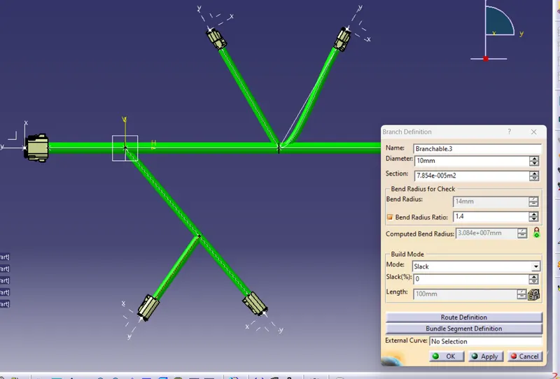
When click on the icon I have to give the diameter value for bundle and also I am entering the bend radius ratio for the bundle. and in the build mode I am selecting the slack mode and give the value for the slack percentage is zero. After entering all inputs as per below image I am click on the Route defination button.
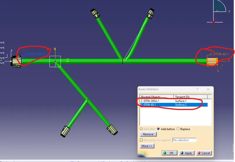
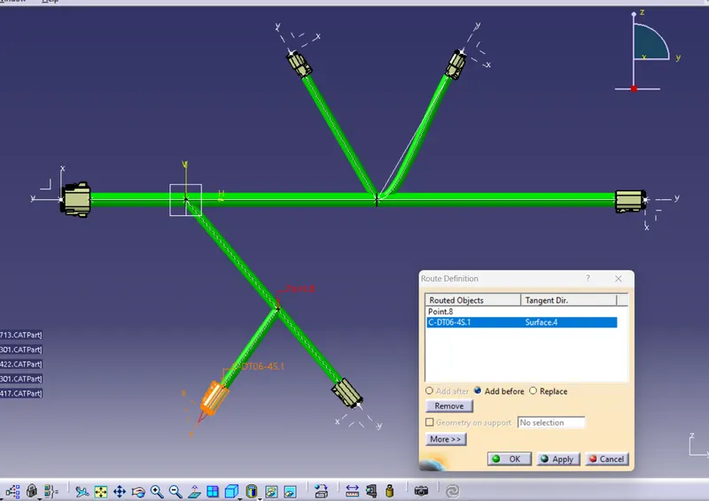
After click on the route defination button the window open as per below image. here in this dialouge box I am selecting two connector bundle entry point one by one, and then click on apply and click ok button and then again click ok button and the bundle is created between this two selected connectors.
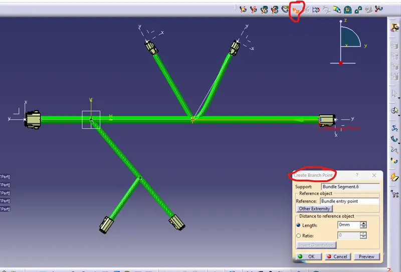
Now for creating the branch point I am selecting the branch point icon as shown in below image and then the dialouge box is open as per below image. here, in the support the ,ain branch is selected which one need two give the branch point. and give the required length for the branch point and click on ok button and the branch point is generated at the required distance.
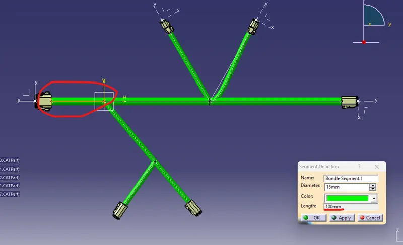
Now I have create some branch point and one of them is shown in the below image. Here I am creating the first branch point at the 100mm distance .
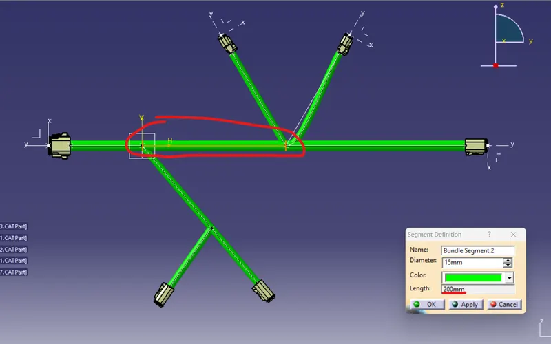
After that I am selecting the remaining main branch and again create the branch point at the 200mm distance. As shown in below image.
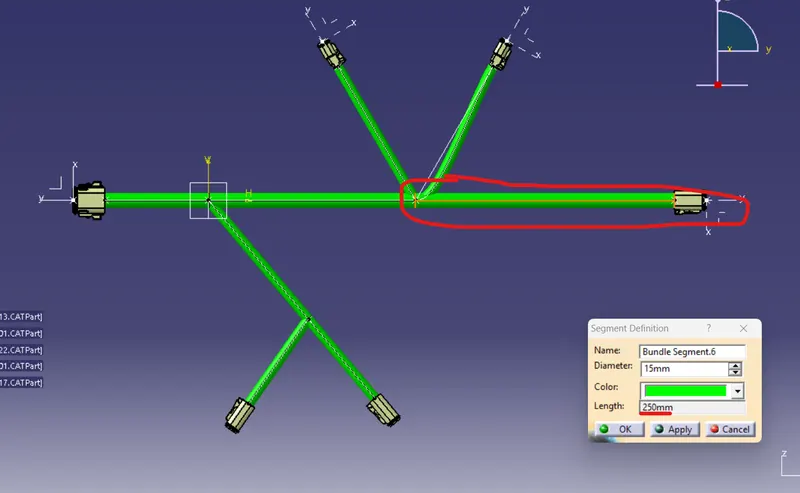
Now, the remaing portion of the main branch is 250mm. As shown in below image.
Now, for defining the other branch bundle I am again click on the branch definition icon and give the input as per the below image.
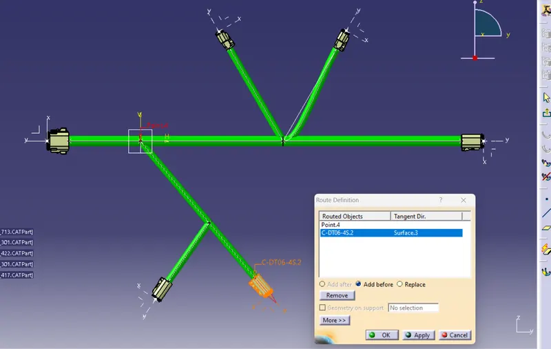
here again click on route definition and select the connectors and one of the branch point. and click on the apply and then ok. and again click ok button and the bundle is creating between the connector and the branch point. As shown in below image.
Now, again I am creating the branch point in this branch. for this i am giving 150mm distance for the branch point as shown in below image.
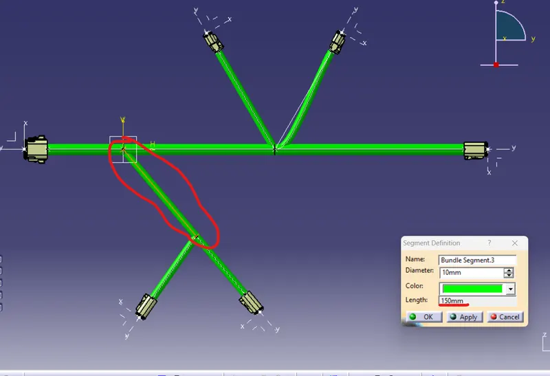
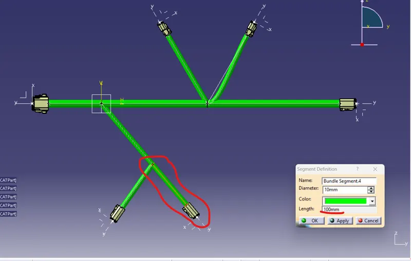
And the remaining portion of that branch is 100mm as per below image.
Now, defining the third branch definition and giving the input as per below image.
And click on route defination and click on the connector and the branch point for the bundle route and click on apply and then click ok. The bundle is created between the connector and the branch point as per the below image.
Same as for the fourth branch I am again click on the branch defination icon and give the value as per the below image.
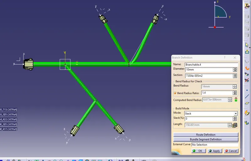
And click the one connector and the another branch point and click on apply and then click ok. The bundle is creating as per below image.
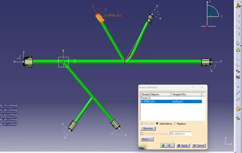
Same as for the fifth branch I am again click on the branch defination icon and give the value as per the below image.
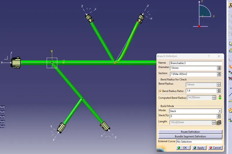
And click the one connector and the another branch point and click on apply and then click ok. The bundle is creating as per below image.
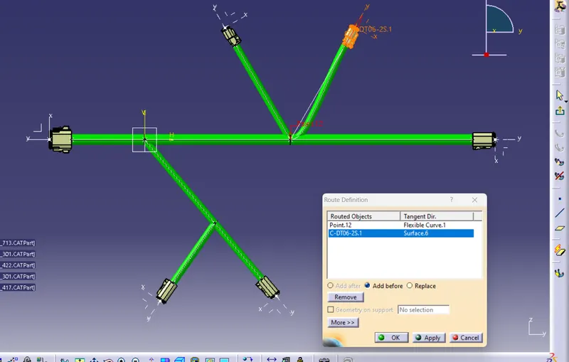
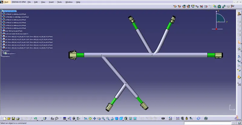
So, In this way whole bundle is created.
Now for defining the protective covering for this branch we need to click on the icon "protective covering".
For this first we have to ensure that we have all required protective covering and the catalouge for the same. If there is no any cataloge then first of all create the all requird protective covering and then add them all in the catalouge.
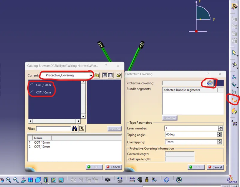
Now, For defineing the protective covering I am click on the icon as shown in below image. and the dialouge box is open. in this dialouge box click on the icon of the catalouge as shown in below image and the catalouge dialouge box is open. from that dialouge box selecting the required size of the protective covering for the wiring bundle.
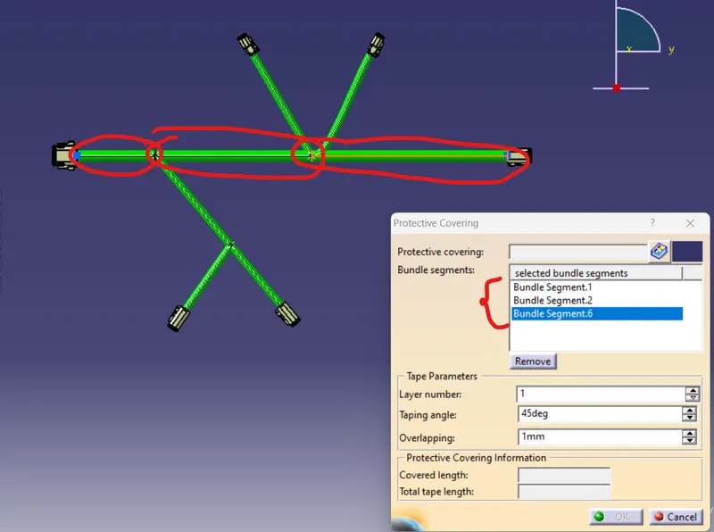
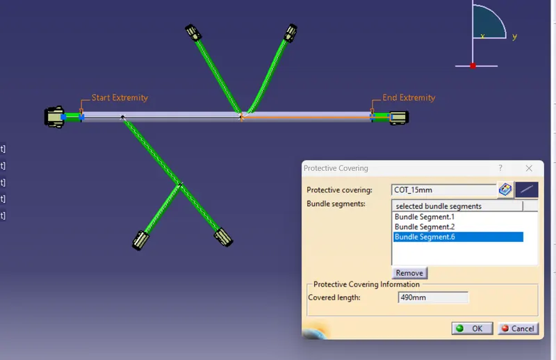
Here, In the bundle segement option I am selecting the branch where I have to provide the protective covering. and add all branch in that as per below image.
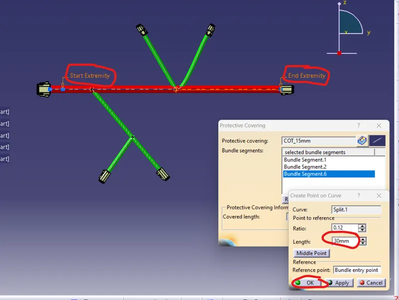
When all inputs are given as per below image the two point is highlighted "start extrimity" and "end extrimity" for giving the distance for the start extrimity doubble click on that point and the dialouge box is open as per below image and provide the distance value ffor the start extrimity point and then click on ok button.
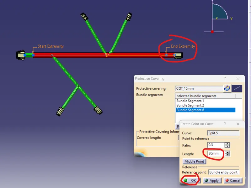
Same as doubble click on the end extrimity point and the dialouge box is open and enter the distance value for the end extrimity point and click on the ok button . In this way I am providing the both end extrmity point distance value as per below image.
Now, After that click on the ok button and the protective covering is visible as per below image.
In this way I am providing the protective covering in all bundle and giving the extrimity distance 30mm in all end. The final wiring harness with protective covering is shown in below image.