Week - 4
Que:1) Implement control logic of a “washing machine” using Stateflow as per given sequence:
- If the power supply is available, the system gets activated
- If the Water supply is not available, stop the process & indicate through LED
- Soaking time should be 200s followed by Washing time of 100s.
- Then rinsing happens for next 20s & dryer runs for 50s
After all the processes have completed turn on the finished LED
ANS:
Google Drive link for the simulink model of the washing machine is given in below:
https://drive.google.com/file/d/1wXLqpK1GiGNoV4eN1SVxCtrrC_kjCyJg/view?usp=sharing
For creating model of the waching machine I am use the 'chart','constant','lamp','slider switch' and 'scope' blocks from the library.
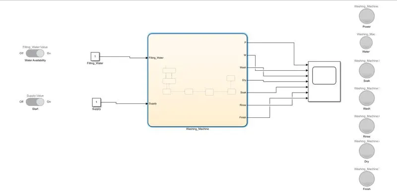
Chart block is used for transition of one state to another state. for the input of the chart block i am use the constant block and which is operated by the switch. and output of the chart block is shown in the scope which is also shown by the lamp block.
First of all add the chart block from the simulink library and click on it which is open the new worksheet of chart block. now here in the stateflow window select the junction icon and create junction for the different state. after that using the different blocks complete the whole model for washing machine simulation.
In the given below figure the whole model diagram for the washing machine simulation.
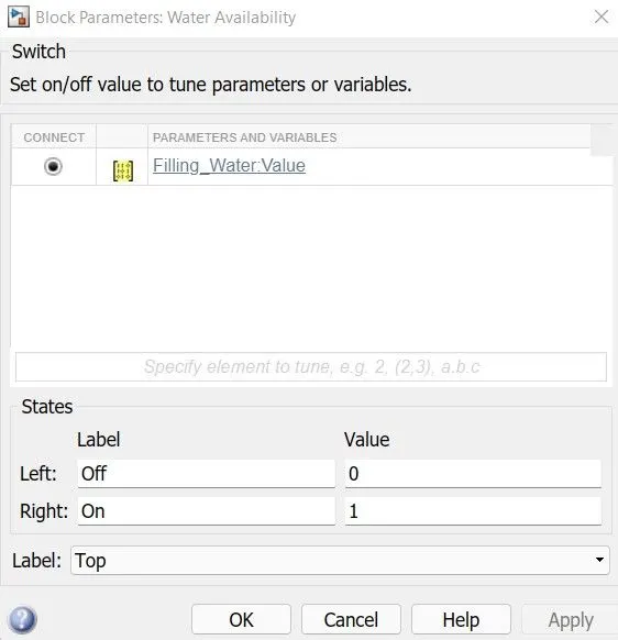
In the below figure I am showing the Input paramete added in different switchs. In the model the switch is connected to the constant value block.
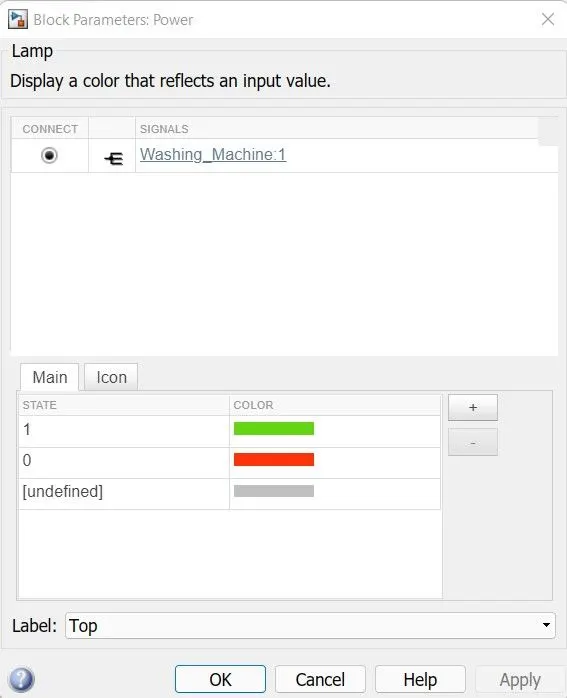
Same as the parameter for the Lamp block is in the given below figure. here in the model different state output is connected with the different lamp.
Now creating the control logic for the washing machine and giving the condition which is given in the question. which is shown in below figure.
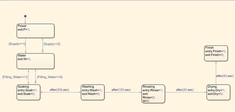
here, in the above control logic first state is power state which is shown the two condition if the value of the supply input is 1 it means the power is on. and if the value of the supply input is 0. it means the power is off and the control logic is shows the red color on the lamp.
now, in the next state I am creating the water state which shows the input condtion of the filling water and according to that it gives the output.
If both state is pass and give the output 1 then it will going to the next state of the soaking state. after the 200sec of the soaking it is moved to the next state which is washing. and after 100sec the state change washing to rinseing. and after 20sec the state change to rinseing to drying and then after 50sec the state change to finish. which is complete the process.
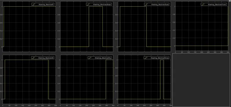
Here, as a output when the 16 sec complete the state is change to soaking so the soaking state lamp shows the green color after 216sec the soaking lamp shows red and washing lamp shows green color. then same as 316sec the washing state is complete so it show the red color and next rinseing state lamp shows the green color. after that 336sec same as rinseing state lamp shows the red color and drying state lamp shows the green color. and at last completion of 400sec the drying state lamp becomes red and the whole process is complete so, finish state lamp becomes green.
Now, Here I am running the Model for 400sec and giving different input and for that the output getting is shown below.
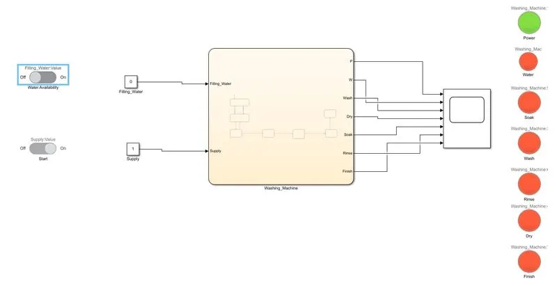
First I am switching on the supply and Water filling is off as input and run the model for 400sec the output as shown in below.
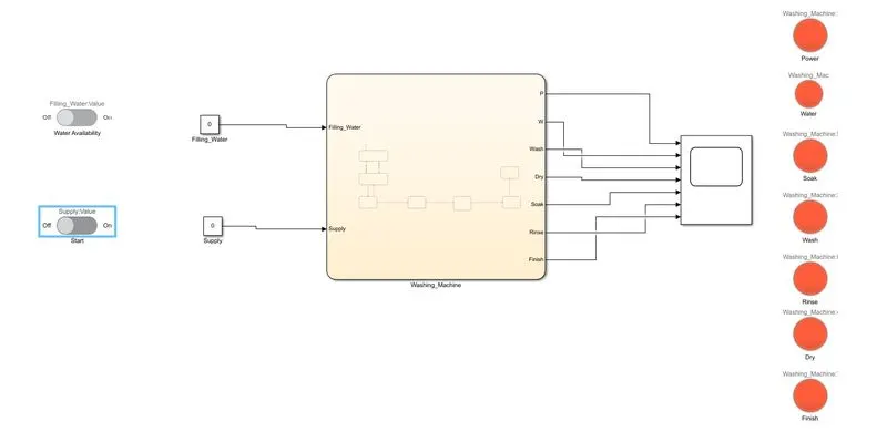
same as next I am switching off the supply and Water filling is off as input and run the model for 400sec the output as shown in below.
Now, I am switching on the supply and Water filling is on as input and run the model for 400sec the output as shown in below.
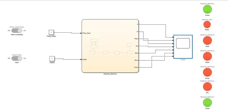
In the given below figure the graphical representation of the output when it is run for 400sec and when the both input is on.
QUE:2) Make a Simulink chart for the “Gear shift” logic as per below conditions:
Speed Range(kmph) Gear
0 to 15 1
16 to 25 2
26 to 40 3
41 to 60 4
Above 61 5
Give speed input while the simulation is running & display the gear number.
ANS:
Google Drive link for the simulink model of the Gear_Shift is given in below:
https://drive.google.com/file/d/1PamIMaVy0_7dRircMfjwWlpEhiMSFfQU/view?usp=sharing
For creating model of the gear shift use the 'chart','constant','lamp','rocker switch' and 'display' blocks from the library.
Chart block is used for transition of one state to another state. for the input of the chart block i am use the constant block and which is operated by the switch and throttal. and output of the chart block is shown in the display which is also shown by the lamp block.
First of all add the chart block from the simulink library and click on it which is open the new worksheet of chart block. now here in the stateflow window select the junction icon and create junction for the different state. after that using the different blocks complete the whole model for gear shift simulation.
In the given below figure the whole model diagram for the gear shift simulation.
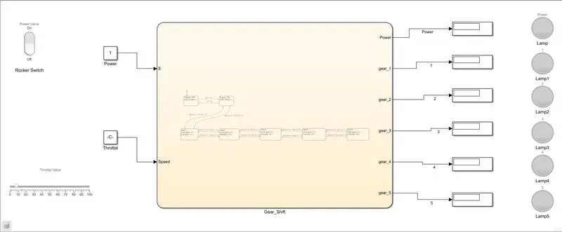
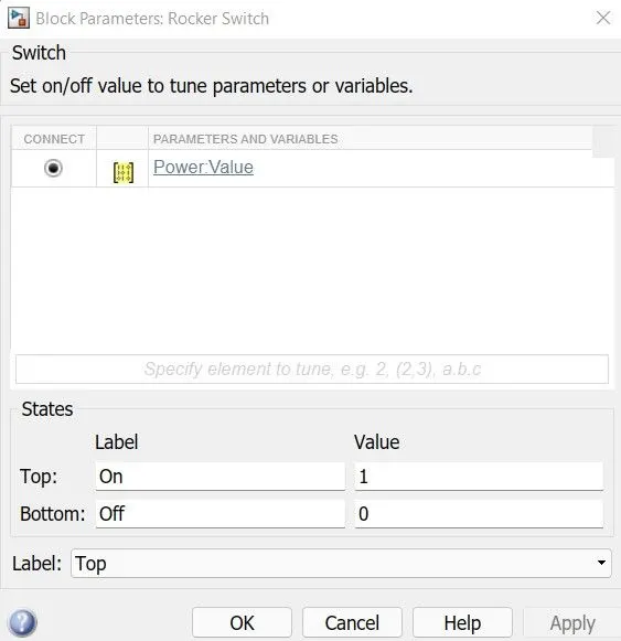
In the below figure I am showing the Input paramete added in switch. In the model the switch is connected to the constant value block. Also the Throttal block is connected with the another constant block.
Now creating the control logic for the washing machine and giving the condition which is given in the question. which is shown in below figure.
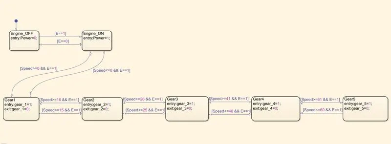
here, in the above control logic first state is Engine state which is shown the two condition if the value of the E input is 1 it means the Engine is on. and if the value of the E input is 0. it means the Engine is off and the control logic is shows the blue color on the lamp.
now, in the next state I am creating the Gear-1 state which shows the input condtion if the speed is between 0 to 15 and according to that it gives the output. After the speed between 15 to 25 it is shows to shift the second gear. and then for the speed of 25 to 40 it shows the change to third gear same as for next 40 to 60 speed the forth and then for speed of more than 60 it is going to fifth gear.
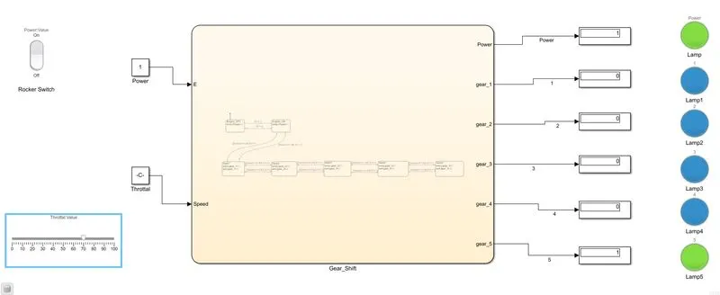
Here, As input use the throttal so for different values of throttal the output of the gear shown in lamp and display.Now,I am running the Model for inf value and giving different input of speed in throttal and for that the output getting is shown below.
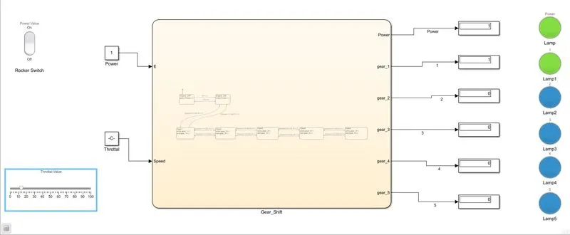
First i am giving the input value for throttal as 12value and as an output getting the gear 1 lamp green and other gear lamp becomes blue.
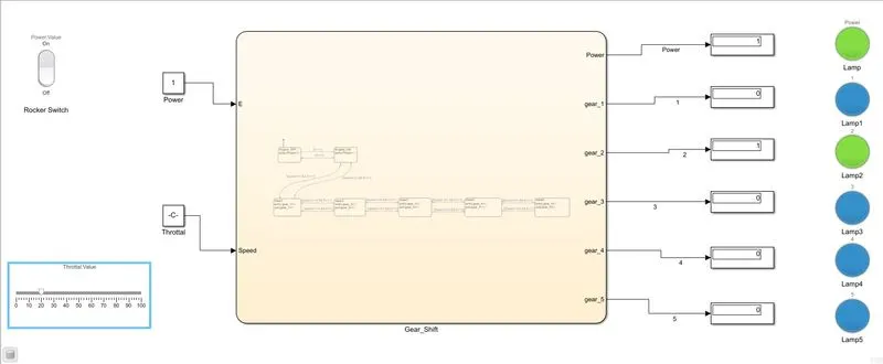
for next i am giving the input value for throttal as 20value and as an output getting the gear 2 lamp green and other gear lamp becomes blue.
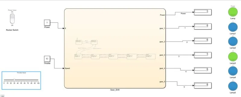
For next i am giving the input value for throttal as 30value and as an output getting the gear 3 lamp green and other gear lamp becomes blue.
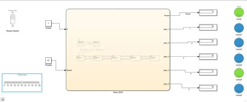
For next i am giving the input value for throttal as 50value and as an output getting the gear 4 lamp green and other gear lamp becomes blue.
For next i am giving the input value for throttal as 70value and as an output getting the gear 5 lamp green and other gear lamp becomes blue.