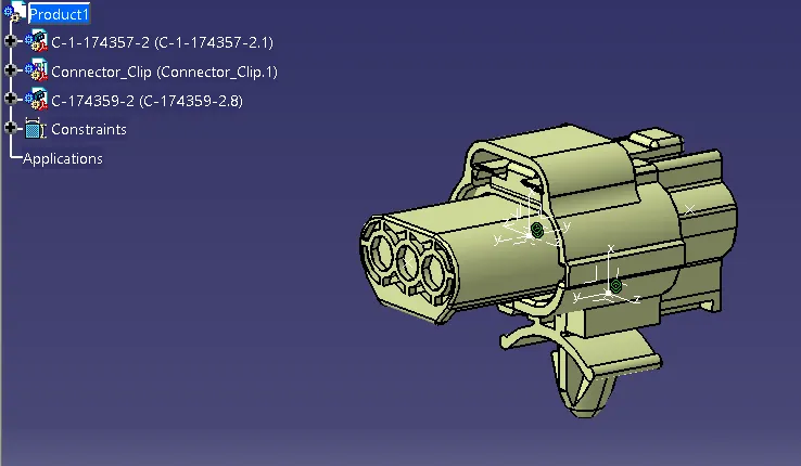
Wiring harness design in CATIA V5 - 3D modeling Week 2 Challenge
EDS (ELECTRICAL DISTRIBUTION SYSTEM) :
EDS basically deals with the physical and logical architecture , schematic development, power distribution, wiring harness design and wiring harness component design for an given electrical system .
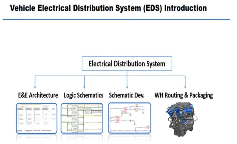
TYPES OF DESIGN FLOW OF EDS SYSTEM :
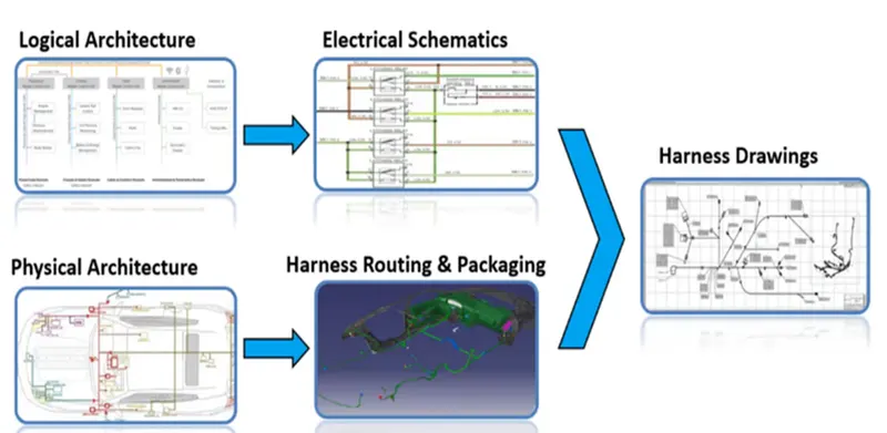
- Physical architecture means the physical location of the electrical component place inside the vehicle.
- Logical architecture means the connectivity of those component in logical level. Example : connectivity between various sensors with ECU ( electronic control unit)
- Power distribution which deals with distribution of power from the battery to the different component which will be distributed with the help of different types of fuses to ensure the wiring harness is safe when there is occurrence of different failure modes
-
E&E ARCHITECTURE : It is high level logical connectivity diagram represents the no. of systems, sub systems and logical connectivity between them. It is also extended to show the CAN (control area network) network between different electronic controller. Example : Air bag ECU (main system) consist of impact sensors as the input and air bag modules, seat belt restrainer as an output.
-
LOGICAL SCHEMATICS : Logical schematics is the detailed design of E&E architecture which extended to show the logical connectivity between different component and control of systems and sub - systems
-
ELECTRICAL SCHEMATICS : Electrical schematic is the detailed design of logical schematic which describes the pin to pin connectivity, properties, fuse distribution, ground distribution, interconnects, wire properties, circuit properties, specification of the component etc. This is the end design of the electrical core design of a system and it is used for the primary input for wiring harness design.
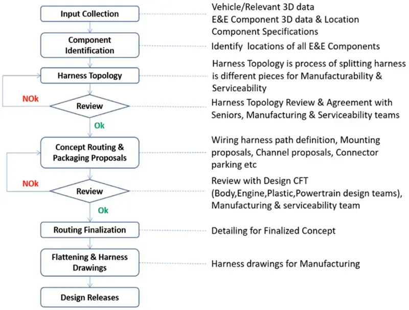
- WIRING HARNESS TOPOLOGY :
Wiring harness topology is the strategy to divide or split the harness between different pieces to achieve the best manufacturability, serviceability and cost effective.
Example 1 : most of the OEM, the engine segment is bought out source from the engine manufacturer like fiat, Tata motors, etc.. Where as the engine manufacturer provides with the all the wiring harness for the engine like fuel injection sensor, engine speed sensor, coolant temperature sensor. And then the engine is assembled inside their vehicle system. The interconnection is used to connect the engine harness with the vehicle harness.
Example 2 : for the serviceability of the door, while the door harness is integrated with the vehicle harness , the whole vehicle harness must be removed. . So to avoid this interconnection is provided.
- WIRING HARNESS ROUTING :
It deals with the desired path of wiring harness into an given vehicle environment by applying the set of design rules and industry practices ,Some of the design rules are harness must be kept away from the exhaust, engine radiators, brake lining.
- WIRING HARNESS PACKING :
It deals with the fixing / mounting strategy of wiring harness routing to ensure the safe and reliability of wiring harness by applying a set of design rules. Some of the design rules are wire bend radius, clamping distance etc.
The term wiring harness refers to the assembly of
- Wires
- Connectors
- Fuse and relay box
- Terminals
- Clips and clamps
- Electronic component
- Guiding channel
- Retention device
- Insulation
- Protection covering
WIRES :
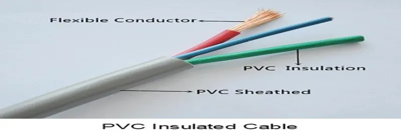
Wiring harness consist of various wires bundled together with each individual wires responsible for carrying the electrical signals and energy used to start the engine, lights meters, navigation systems, power windows , door and other devices in vehicle.
CONNECTORS :
An electrical connectors, is an electro mechanical device used to join electrical termination and create an electric circuit. Electrical connectors consist of housing, terminals, wedge locks, seals, cavity, mounting cam etc.. Connectors are plastic molded housing with locking and retention features.
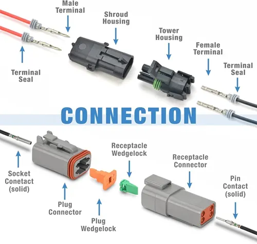
TERMINALS :
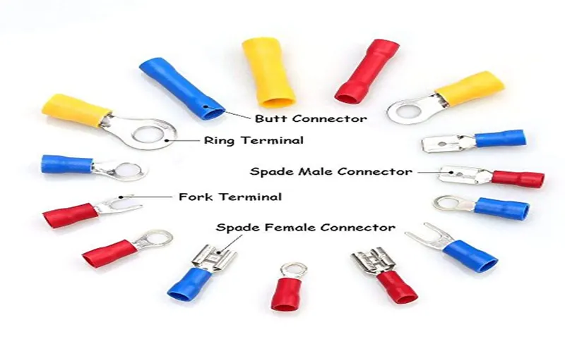
A device designed to terminate a conductor that is to be affixed to a post, stud, chassis , another tongue etc.. To establish the electrical connection. Terminals are metal conductors (mostly brass) with plating constructed in specific shape.
Types of plating :
- Tin plating
- Silver plating
- Gold plating
The purpose of using different plating is to secure the joints from the environmental condition and to provide the minimum electrical resistances.It means the gold is more secure , anti corrosion material and also have less electrical resistance while compared to tin and sliver
Gold plating are very expensive and used for very sensitive loads where very low voltage signals are also monitored . Example air bag connections
In case of high current circuit. it is not advisable for either gold or silver. The tin plating will make the purpose and use of the terminals
PROTECTION DEVICES :
CORRUGATED FLEXIBE TUBES :
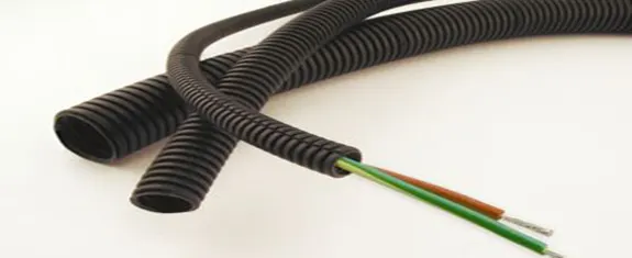
- Corrugated flexible tubes are also known as cot tubes / convoluted conduits have a wide range of application in automotive industries.
- They are made of plastic material and also flexible.
- This tubes helps to protect harness from thermal and physical damages and sometimes it is used to improve appearance of the harness.
- Corrugated tubes are available in many sizes, colors and different temperature range.
- Sometimes the yellow cut tubes are used in the highly safety systems such as air bags.
- In some instance silicon polymer coverings are used in the case of very high temperature up to 300 degree Celsius such as exhaust
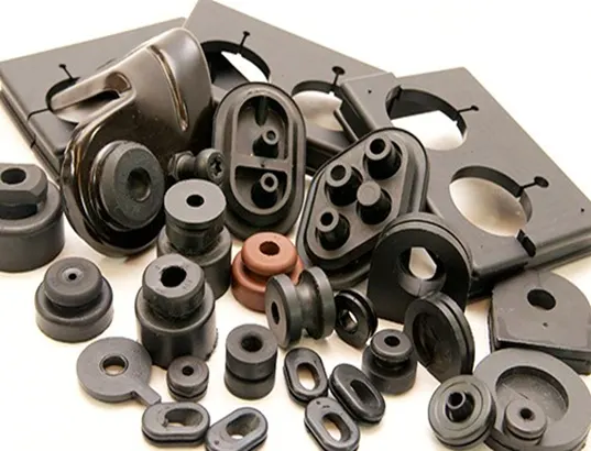
SEALING GROMMETS:
- Grommets are mainly used for three purposes
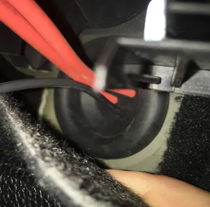
- Sealing, protecting, and to adsorb vibration and shock.
- Grommets are the rubber molded components used in the protection of wiring harness as described.
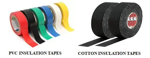
INSULATION TAPES :
- Insulation tapes are adhesive / non adhesive tapes and sleeves.
- They are made up of PVC / cotton polymer material.
- The main purpose of the insulation tape is to align the wiring harness in the systematic arrange so that it can form a circular bundle.
- The cotton tapping application is mainly they are demanded in high temperature like engine area. Cotton tapping have very high temperature resistance.
STANDARD CABLE STRAP :
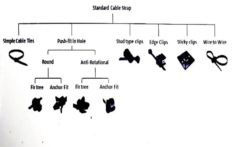
- Simple cable tie : used to mount the wiring harness with some metallic bracket. This are also widely used in our daily life.
- Push fit in hole has two types one is round and another is anti rotational type clip.
- Round type clip can be rotated even after the clip is fixed.
- Anti rotational clip cannot be rotated after the clips being fixed.
- In the sub classification we have fir tree type and anchor tree type clips.
- Fir tree clip is more firm than the anchor fit clip.
- Then we have clips which are suitable to fix into studs. (stud type clips)
- Clips which are used to fix at the edge of the panel. (edge clip)
- If edge, stud or holes are not available we can also go we the sticky clips.
- Wire to wire clips which is also known as double headed cable tie.
- Use of edge and sticky clip are not preferable choice because while using the edge clip it can scratch and remove the paint coating. This can cause the rust formation and prevents damages.
- And for sticky clamp it is not preferable due to its stickiness during the long run period.
SEPARATOR CLAMPS :
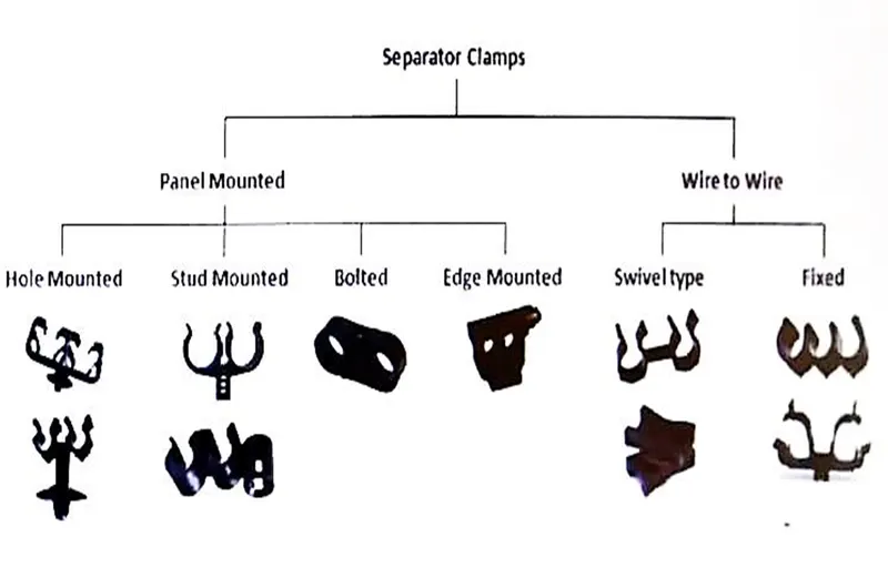
- Separator clamps are used to separate wiring harness from something.
- This clamps are used when we have wiring harness routing along with the hoses, pipes or two wiring harness are routed together.
- So this clamps are used to maintain the specific distance between to two running wiring harness routing or wiring harness and pipes.
- These are classified into two panel mounted and wire to wire.
- Panel mounted can be fixed at the any body part.
- Wire to wire clamps are those which mounting to the panel is not necessary or not provided.
- This is also used to ensure the positive clearance between different components which are mounted parallel.
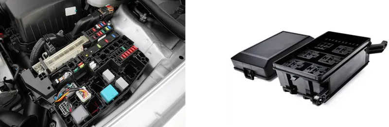
FUSE AND RELAY BOX :
- These are the plastic molded parts used to packages fuses and relay in systematic manner.
- It also used to protect them from damages. [physical and environmental]
- The selection of fuse and relay box depends on the number of fuse and relays required in a system
RETENTION DEVICE:
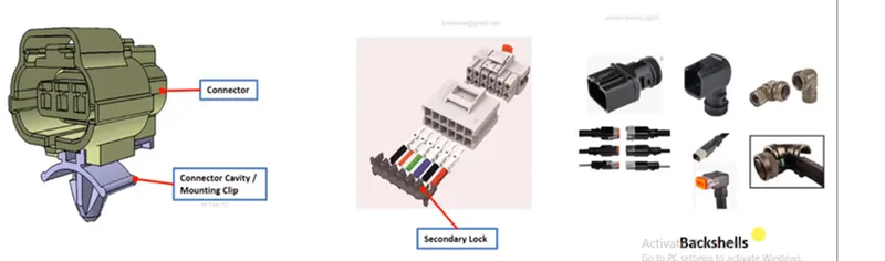
- These are plastic molded parts used to mount connectors and other harness components (connector mounts, secondary lock, connector back shells etc..)
- Connector cavity / connector mounting clip : they are used to mount the interconnection to the body . And ensure the wiring harness connection is loosen it , while during the vibration or running conditions
- Secondary lock : which is used to ensure the secondary lock of the terminal.
- The primary locking is provided with the terminal itself where it is the part of the connector plastic housing.
- Secondary lock is not the mandatory one, based on the complexity the designer can chose it.
- Back shells are the dressing devices or the packing devices which are used at the end of the connectors.
WIRING HARNESS DESIGN PROCESS :
WIRING HARNESS USING CATIA V5 :
FEMALE CONNECTOR :
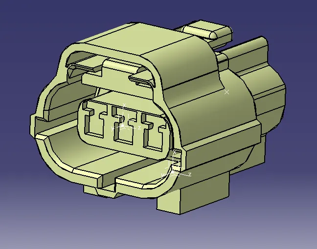
step 1 : the female connector is downloaded from the above link.
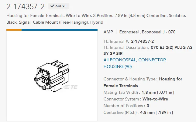
step 2 : defined the axis system for connector connetion point, cavity connection point and define point for bundle entry in the part work bench.
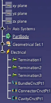
step 3 : then in the electrical part design, define the above component as the connector and also define its connector connection point, cavity connection point and finally define the bundle entry point.
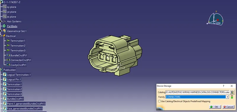
step 4 : save the female connector in the connector catogue which can be done using store device command.
MALE CONNECTOR :
step 1 : the male connector is downloaded from the above link.
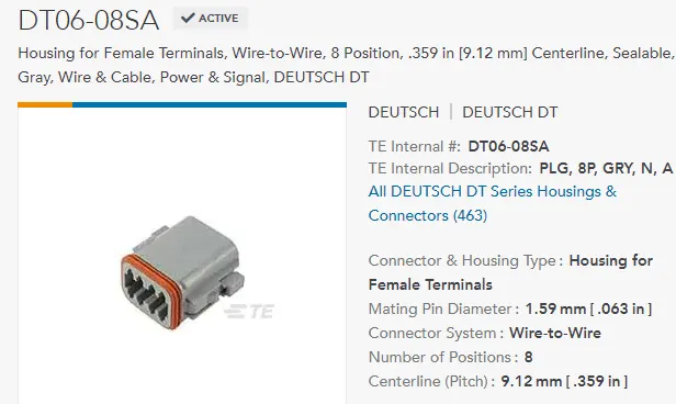
step 2 : defined the axis system for connector connetion point and then define a point for bundle entry in the part work bench.
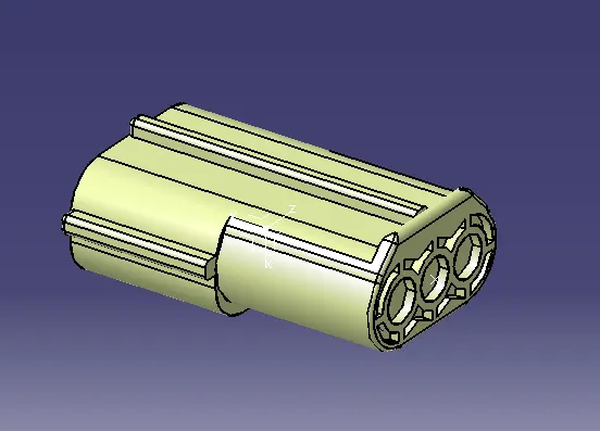
step 3 : then in the electrical part design, define the above component as the connector and also define its connector connection point and define the bundle entry point.
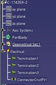
step 4 : save the male connector in the connector catogue which can be done using store device command.
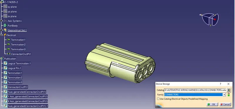
CONNECTOR CLIP :
step 1 : the connector clip is downloaded from the above link.
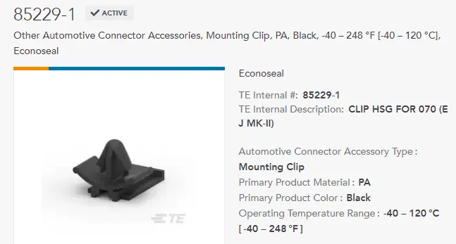
step 2 : defined the axis system for cavity connection point in the part work bench.
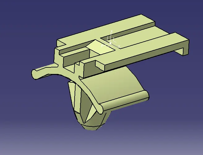
step 3 : then in the electrical part design, define the above component as the cavity and also define its cavity connection point.
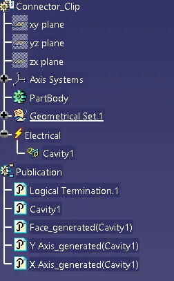
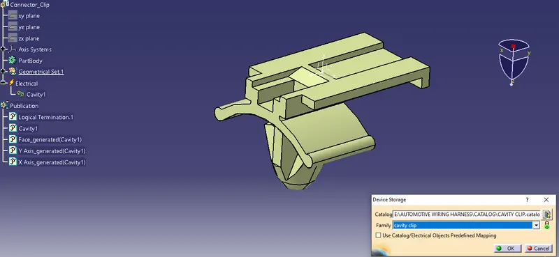
step 4 : save the cavity connector in the cavity catogue which can be done using store device command.
CATIA ELECTRICAL ASSEMBLY DESIGN :
step 1 : open all the defined component in the electrial assembly design workbench.
step 2 : align the define component with appropriate mating region.
step 3 : then connect all the components using the connect option.