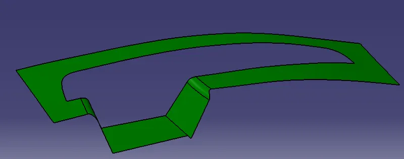
Week 8 - Challenge 6 - Core & Cavity Design
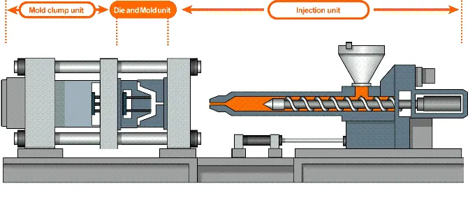
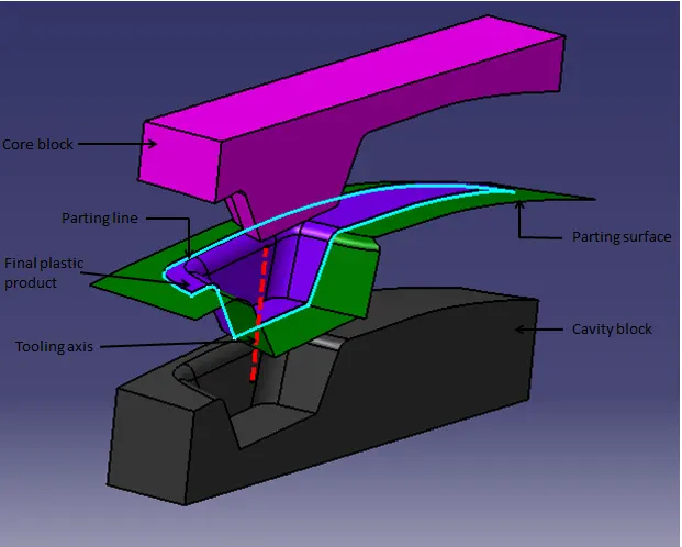
CORE BLOCK :
core has the projection where it tends to be a movable block. the movable unit (core) comes in contact with the cavity where the injection of molten metal takes place. the movable side consist of an ejector pin where the component gets cooled and ejected out using the ejector pin.
CAVITY BLOCK :
cavity has the depression where its tends to be a fixed block. In this the molten metal will flow through the runner and enters the gating system where it reaches the cavity with high pressure and temperature.
TOOLING AXIS :
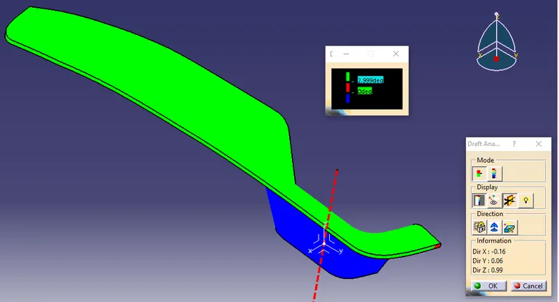
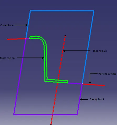
this is the most important design consideration where the component should be manufacturable with those mould axis. the area which in green colour is can be moulded in the core block and the area in the blue colour can be manufactured using the cavity block.
PARTING SURFACE :
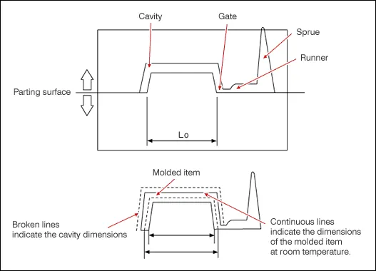
generally injection moulding has two major components fixed and movable half, these two sides are pressed tightly and form a sealed hallow to avoid plastics melt flow leakages. the surface which is pressed is called as parting surface.
the parting surface should not lie on the class A surface. due to the flash occur there will some excess of material will get bluged of in the parting surface. if it in the B surface, there might be no issues because the B surface will get assmbled and may not be visible. but in the case of A surface, the flash defect may cause the decrease the levelof asthestics.
CREATION OF TOOLING AXIS :
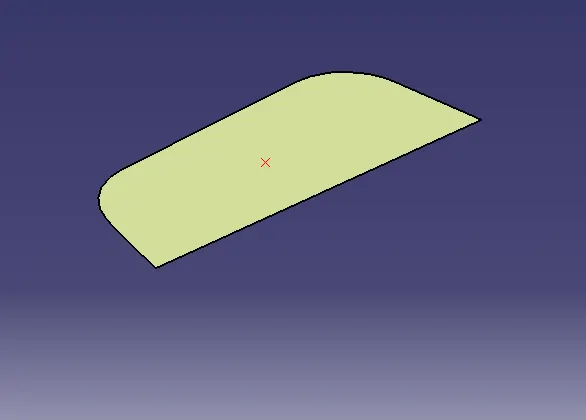
- extract a base surface in CLASS A and create a point with (0,0) co ordinates.
- The class A surface has a two planar faces to be cleared, so line must be common with the both the axis.
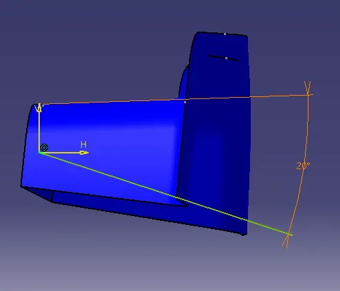
- so in the xz plane there is only one planar faces , hence the angle is created and modified according final draft values
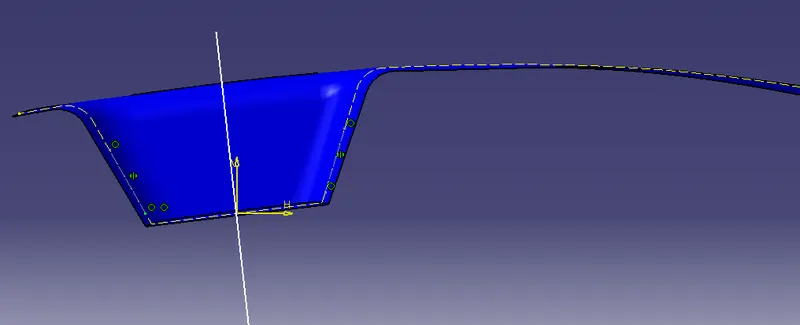
- the other plane is yz plane, in this we can find the two faces in which the line has drawn colinear to the draft surface.
- then the two lines are bisected to get the axis for yz plane.
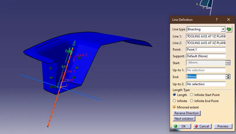
- with the help of this xz plane axis and yz plane axis we can find the bissection line and get the tooling axis which is common for both the planes
CREATION OF DRAFT ANALYSIS IN CLASS A SURFACE :
- after creating the tooling axis go to, inert - analysis - draft analysis ,
- in that place the three axis system in the line of tooling axis
- then fix the position
- click any place in the class A surface to get the final draft analysis report.
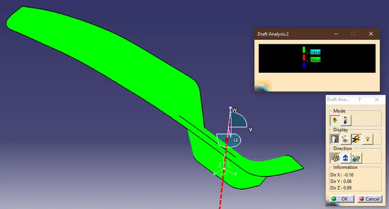
CREATION OF DRAFT ANALYSIS IN FINAL PLASTIC PRODUCT :
EXPLODED VIEW OF CORE BLOCK , CAVITY BLOC AND PARTING SURFACE.
- both core and cavity block is drafted along the tooling axis.
- the parting line is the junction between the core half, cavity half and the parting surface.
ISOMETRIC VIEW : (OVERALL)
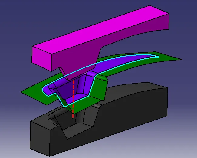
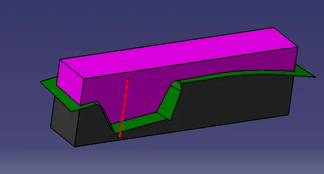
ISOMETRIC VIEW : (CAVITY BLOCK)
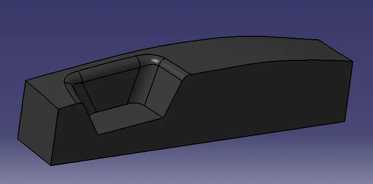
TOP VIEW : (CAVITY BLOCK)
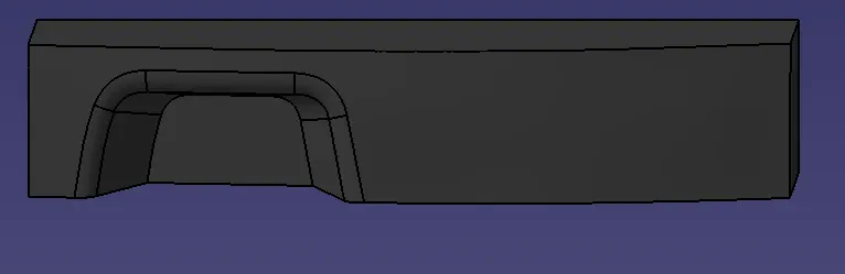
FRONT VIEW : (CAVITY BLOCK)
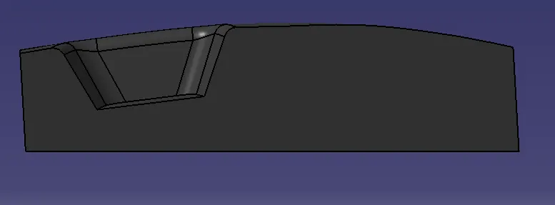
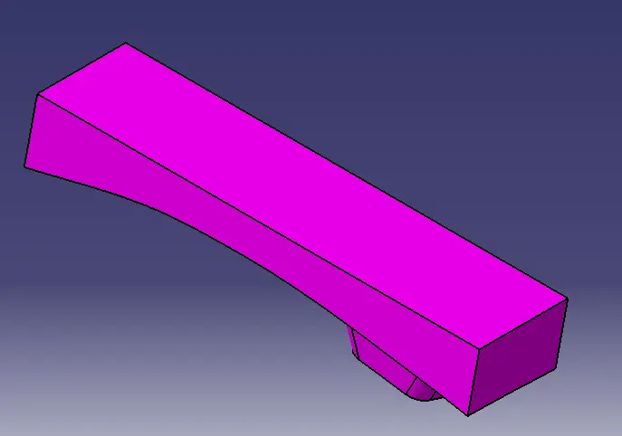
ISOMETRIC VIEW : (CORE BLOCK)
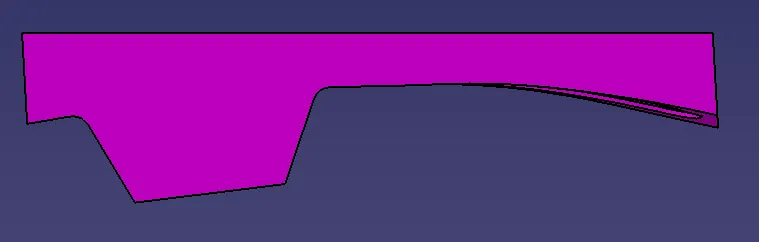
FRONT VIEW : (CORE BLOCK)
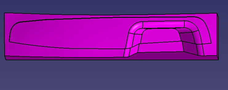
BOTTOM VIEW : (CORE BLOCK)
PARTING SURFACE :