Fender Design Challenge
OBJECTIVE :
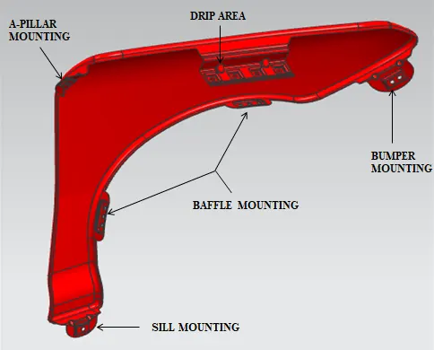
Design of front fender and provide with the Drip mounting, A-pillar, Sill, Bumper and Baffle (splash) Mounts with the required design consideration and understand the DFMA of the frond fender .
PROCEDURE :
- Introduction
- Types of front fender
- Mounting points on fender
- Design consideration
- Manufacuring process
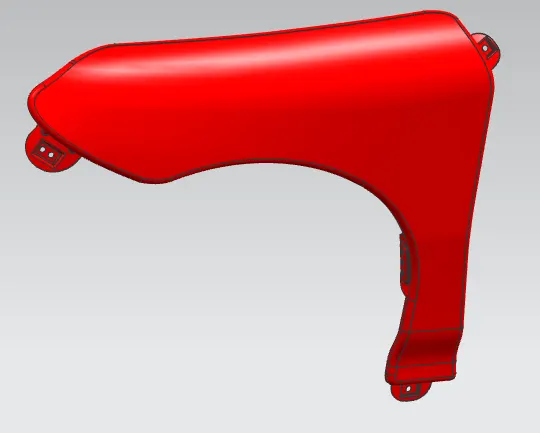
- Front fender design in NX
- Conclusion
INTRODUCTION :
fenders are the part of automobile, motorcycle or any other vehicle body that frames the wheel well. its primary purpose to prevents the vehicle body from stones, mud, sand and other road spray which tends to spill inisde while the wheel is rotating. this may cause damages to the engine as well as to prevent injuries to the passengers inside the car. they are typically grid and damages the contact between the road surface and the vehicle body. In motorcycle , the fender is not a integrated part of monoque . it has to be mounted separately. It is also know as mud guards in motor cycles. the fender opening for the wheel is much larger than the wheel diameter. its is due to avoid contact between the wheel and vehicle body (because they donot move with the wheel suspension), better NVH . This also known as the wheel arch area. mostly passenger vehicle have four fenders , one at each of the wheel. in narrow body vehicle, the fender is exposed curved on top the wheel where the wheel is exposed outside the fender, where as the wide body vehicle. the fender covers the wheel and it is not seen from the front end of the vehicle.
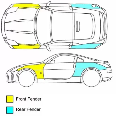
TYPES OF FRONT FENDER :
there are two types of front fender
- fully bumper type
- half bumper type
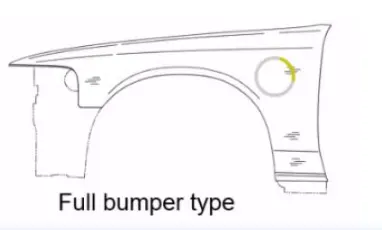
FULL BUMPER TYPE:
It is the traditional type of fender, where more material has been used and the wheel is fully covered. due to its more material weight, there has been an impact in the efficieny fo the vehicle. the maintanace cost is also high due to its fully covered area.
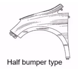
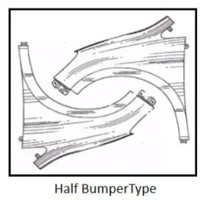
SEMI / HALF BUMPER TYPE :
To over come the problem faced in the fully bumper type, the semi / half bumper type is introduced. where the usage of material is reduced and there by slightly increasing the blank sisze we can provide a two fenders per blank. this is called as scrap management. half bumper type gives more productivity ratio and lesser cost than the full bumper type.
MOUNTING POINTS ON FENDER :
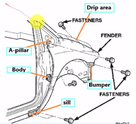
- Drip area
- Bumper
- Sill
- Baffle / splash
- A-pillar.
DRIP AREA :
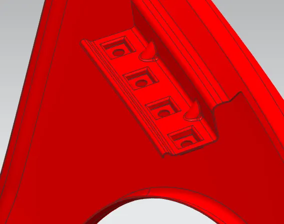
There are several design consideration for designing drip area mounting, is that there must be minimum of 200 mm of gap at the rear end of the fender , this is due to the space for the cowl mounting.
and other consideration is that there must of 150 mm minimum gap at the front end due to the gap for head lamp mounting. the drip area mounting is at the engine compartment.
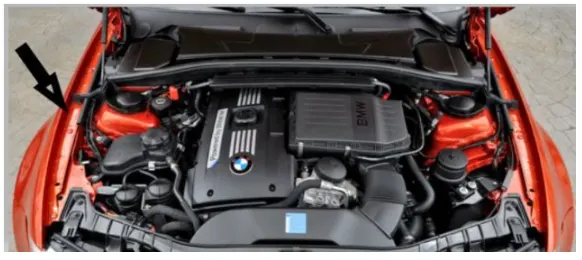
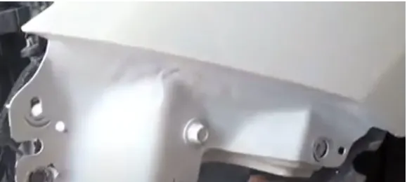
BUMPER :
the bumper mounting region is at the frond end of the fender and mounted by using brackets.
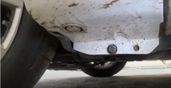
SILL :
Sill mounting is on the bottom of the fender and mounted by using the brackets
BAFFLE / SPLASH :
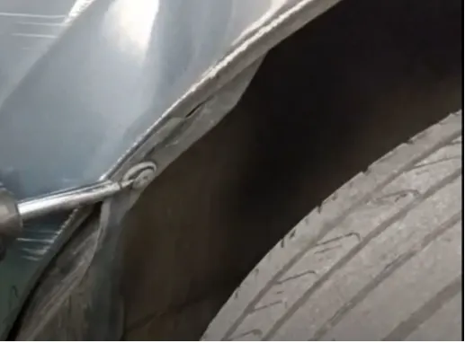
it is one the important region where baffle is mounted. this region is used to prevent damages in vehicle body due to spillage of stones, mud and other road spray. it is mounted by using brackets.
A-PILLAR :
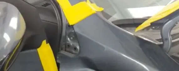
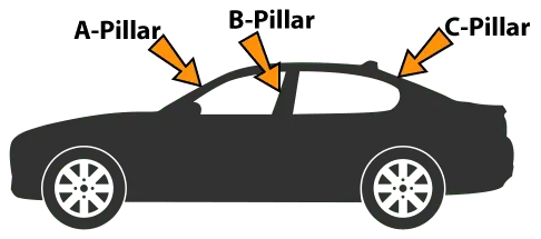
In this, fender is mounted on the A - pillar of the vehicle.
DESIGN CONSIDERATION :
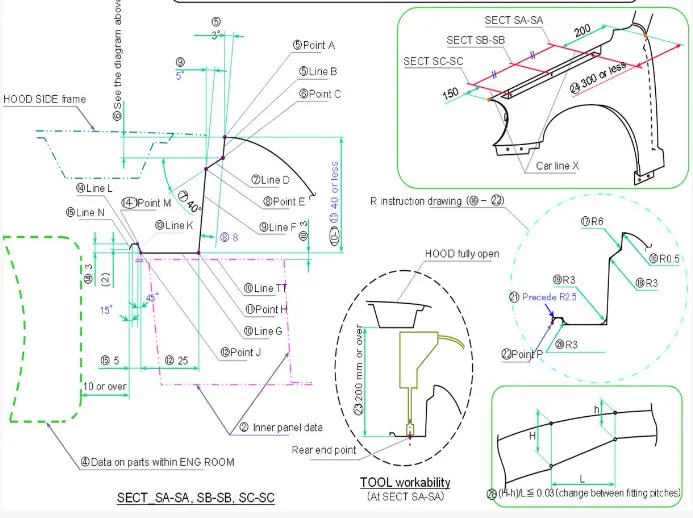
- The first and foremost design consideration is calcuating the region for drip area. where minimum of 200 mm gap at the rear end should be maintained for cowl mounting region and 150 mm gap at the front end should be maintained for head lamp mounting.
- minimum of 10 mm gap should be maintained between the engine room and the drip mounting area.
- the depth of drip area must be maintained less or equal 40 mm, for production feasability , if it is more than 40 to less than 60 mm then it must be provided with the rigidity bead (drat) for better stiifness. when it exceeds to more than 60 mm, spring back action takes places thus design for manufacturing feasiblity failed here.
- deep drawing angle must be more than 3 degree to make the tool come out / return while manufacturing.
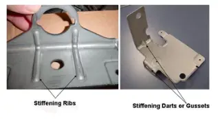
- dart must be provided for all perpendicular surfaces to get more stiffer.
- minimum flat surface of 5 mm at each side should be provided for fastnening holes.
MANUFACTURING PROCESS :
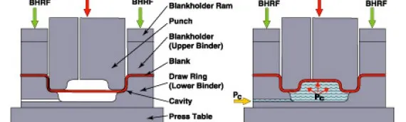
DEEP DRAWING :
It is a forming process which occurs under a combination of tensile and compressive conditions. A flat sheet metal blank is formed into a hollow body open on one side or a hollow body is formed into a hollow body with a smaller cross-section
In pure deep drawing there is no reduction of sheet metal thickness, forming is achieved in stretch forming purely as a result of a decrease in sheet metal thickness. Stretch forming is extensively used for the forming of only slightly curved parts with low depth of draw (e.g. roofs, doors).
When drawing complex car body parts in practice, usually a combination of stretch and deep drawing involved. It is necessary that the sheet metal is stretched as well as possible without reaching the material’s limits (e.g. splits, wrinkles).
V BENDING (DART) :
the most common method used with press brake bending. An acute angle ground on both the punch and die can provide adequate overbending of the metal. Also, the bending amount can be altered by adjusting the amount of coining the metal undergoes at the bottom of the press stroke.
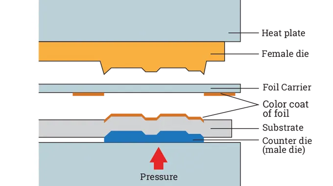
EMBOSSING :
Embossing is the stamping operation for produing raised and sunken designs in sheet metal. this process is done by placing a sheet metal between male and female die.
FRONT FENDER DESIGN IN NX :
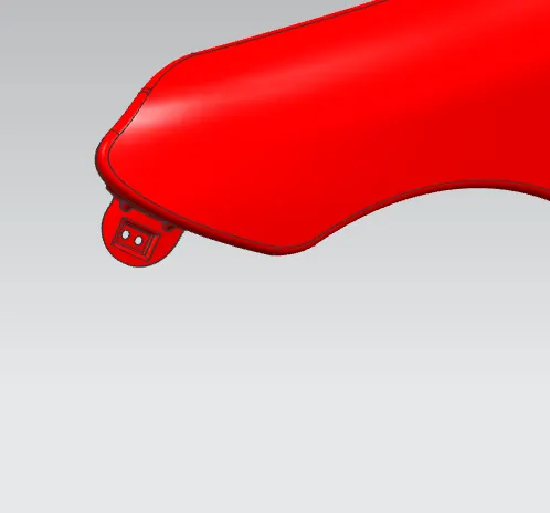
BUMPER MOUNTING
SILL MOUNTING
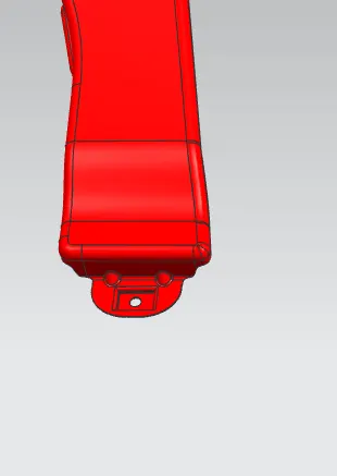
SPLASH / BAFFLE MOUNTING
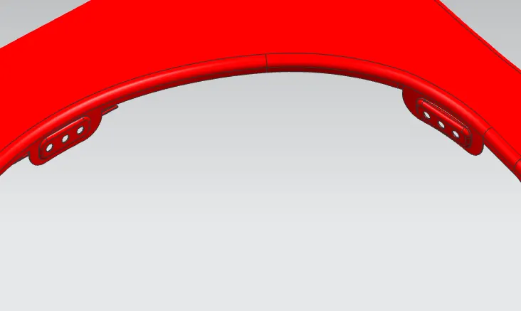
A-PILLAR MOUNTING
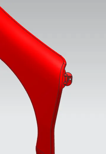
DRIP AREA
CONCLUSION :
thus front fender has been design with respective to design consideration and with DFMA standards.