Wiring harness design in CATIA V5 - 3D modeling Week 4 Challenge
CONNECTORS :
Connectors are parts or devices used for electrically connecting or disconnecting circuits etc. They can connect and disconnect by hands or with simple tools without requiring special tools or processes such as soldering.
THE CONNECTORS USED IN THE GIVEN ASSIGNMENT ARE :
- DT06-08SA
- DT06-4S
- DT06-2S
- DT06-6S
STEP 1 : DEFINE THE GIVEN CONNECTOR AS ELECTRICAL
- first step is creating mechanical properties of the connector in the catia v5 part design.
- create an axis system in the centre of the connector connection point and use the default oreintatation of the axis in all the connectors
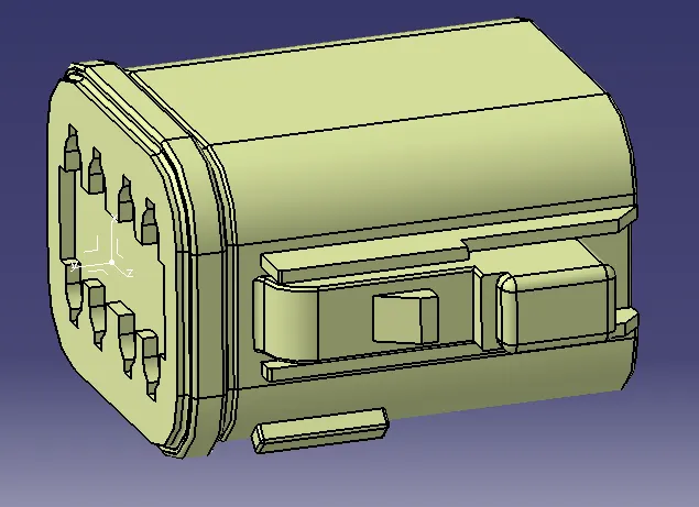
- and create the point for the bundle entry segment in the connector .
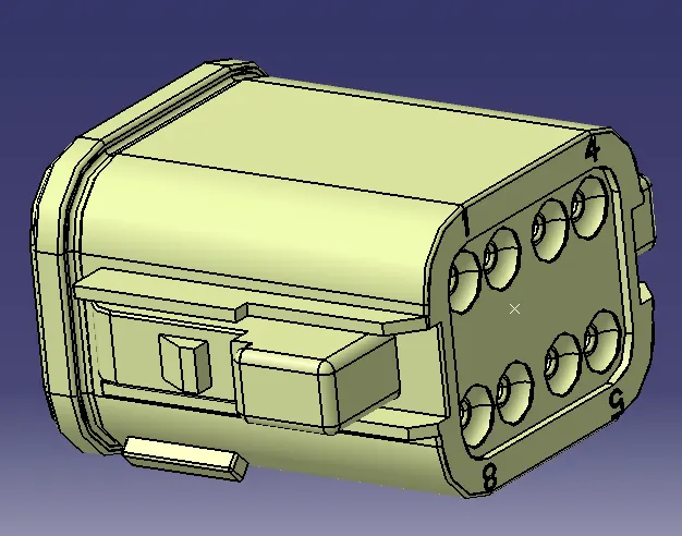
- then in electrical work bench define the part as the connector.
- and the define the no. of terminals in the connector. example : the terminal no. is given the part no itself i.e DT06-08SA where 8 is the no. of terminals.
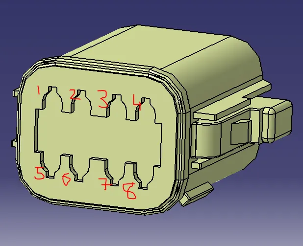
- if it is not mentioned in the part no. check the no. terminals in the connector connection point. refer the above image.
- after defining as the connector, make define of connector connection point.
- define the appropriate axis system, face to coincide and oreintation of the connector in connector connection point.
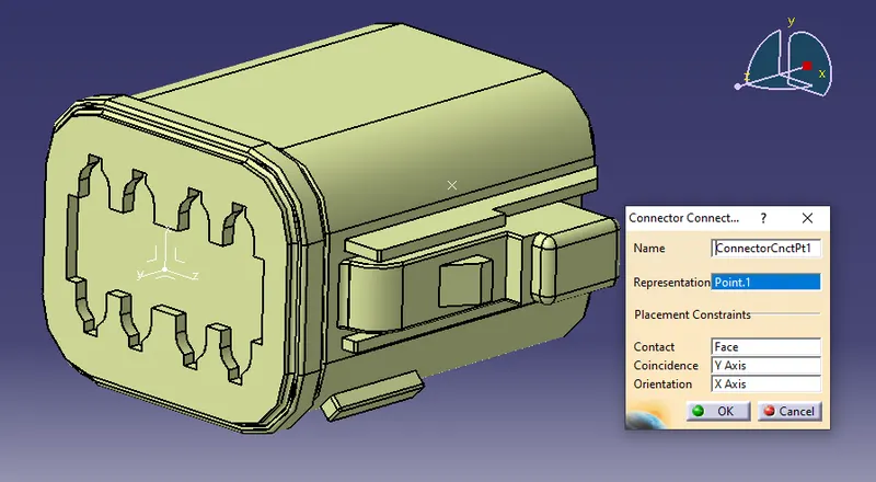
- after that define the bundle entry point for the connector.
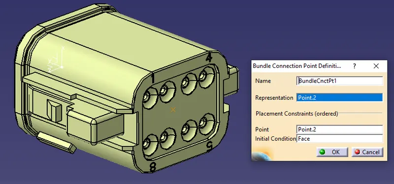
- similarly define it for all the 3 connectors. and save in the separate catague named as connectors
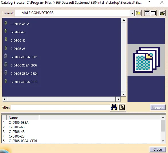
STEP 2 : WIRING HARNESS ROUTING LAYOUT
- for an easy and accurate connector position, use the predefined sketch for assemble the connector
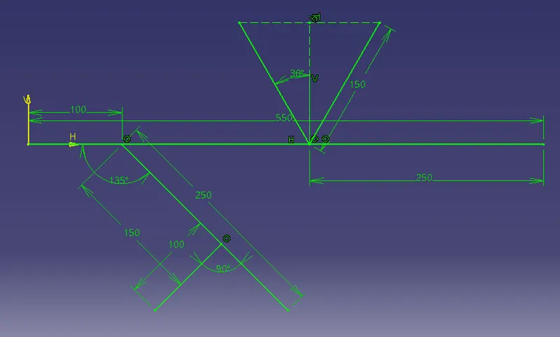
- and open a new product and insert all the required connectors in the product file, then assembly the connector accordingly to the given layout.
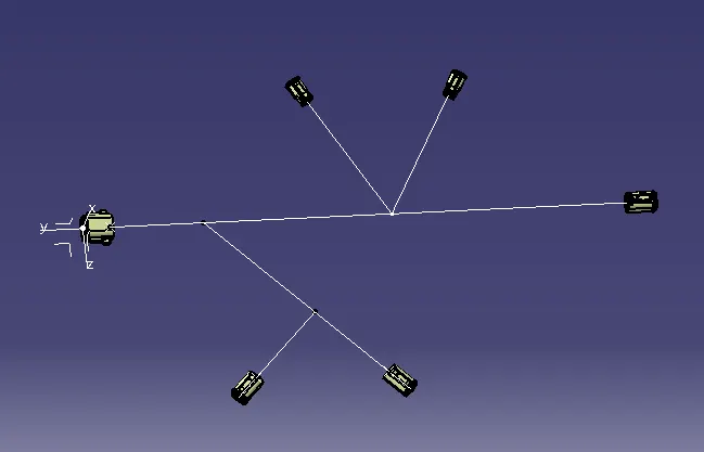
STEP 3 : ELECTRICAL HARNESS ASSEMBLY
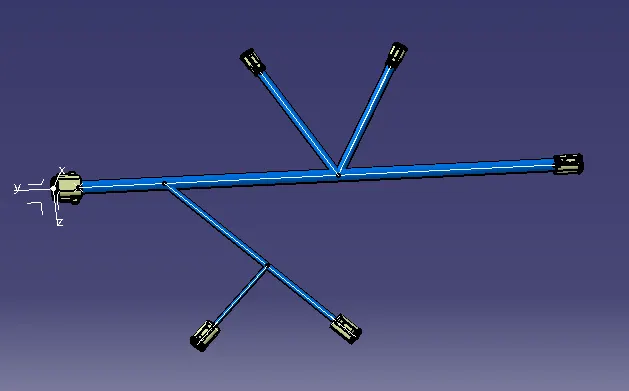
- then open the electrical harness assembly, define the product file as geometrical bundle.
- click on multi branchable icon,and define the branchable segments for all the connectors as the required layout.
- bundle dia is assumed as the following.
- the bundle bend radius must be 1.4 - 1.6 of the dia.
STEP 4 : PROECTIVE COVERING
there are two types of protective coverings are used in the automotive wiring harness.
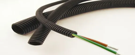
- corrugated flexible tubes
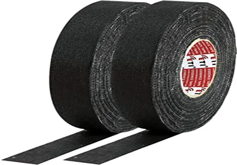
- insulation tapes
- CORRUGATED FLEXIBLE TUBES :
COT tubes are made of plastic material and easily flexible. this helps the wiring harness from thermal and physical damages and also gives the better asthetic apperance of the harness. whereas the yellow COT tubes are used for the high voltage safety systems such as air bags.
- INSULATION TAPES :
they are made up of pvcor cotton polymer material. The main purpose of the insulation tape is to align the wiring harness in the systematic arrange so that it can form a circular bundle. The cotton tapping application is mainly they are demanded in high temperature like engine area. Cotton tapping have very high temperature resistance.

PVC TAPE
COTTON TAPE
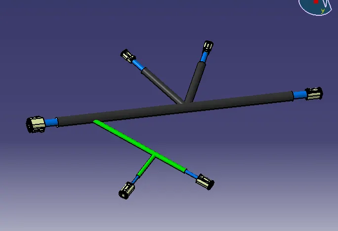
- In the given wiring harness layout, the branch which is black colour protection covering is corrugated tubes and where as green colour protective covering indicates the pvc tapes.
CONCLUSION :
The wiring harness routing has been defined and protective covering has been installed with the given layout and connectors where as the bundle dia is keet as an assumption.