Wiring harness design in CATIA V5 - 3D modeling Week 5 & 6 Challenge
WIRING HARNESS TOPOLOGY :
Wiring harness topology is the strategy to divide or split the harness between different pieces to achieve the best manufacturability, serviceability and cost effective.
FOR EXAMPLE :
most of the OEM, the engine segment is bought out source from the engine manufacturer like fiat, Tata motors, etc.. Where as the engine manufacturer provides with the all the wiring harness for the engine like fuel injection sensor, engine speed sensor, coolant temperature sensor. And then the engine is assembled inside their vehicle system. The interconnection is used to connect the engine harness with the vehicle harness.
CONNECTORS :
An electrical connectors, is an electro mechanical device used to join electrical termination and create an electric circuit. Electrical connectors consist of housing, terminals, wedge locks, seals, cavity, mounting cam etc..
Connectors are plastic molded housing with locking and retention features.
the connectors used in the harness A for this assignment are
- c-dt04-08pa-c017-99-3d (connector 6)
- c-1-174357-2-e-3d (connector 7)
- c-dt06-08sa-ce01-99-3d (connector 8)
- c-dt06-08sa-ep07-99-3d (connector 9)
- c-ydts26f15-35snv001-99-3d (connector 10)
the connectors used in the harness B for this assignment are
- c-ydts26f15-35snv001-99-3d (connector 1)
- c-dt06-3s-cp01-99-3d (connector 2)
- c-dt06-08sa-ce04-99-3d (connector 3)
- c-dt06-08sa-ep07-99-3d (connector 4)
- c-dt06-08sa-ce13-99-3d (connector 5)
GIVEN LAYOUT FOR THIS ASSIGNMENT :
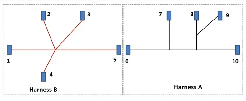
FOR THIS FOLLOWING STEPS, THE FEMALE CONNECTOR c-1-174357-2-e-3d is taken as an example.
STEP 1 : DEFINE THE GIVEN CONNECTOR AS ELECTRICAL
- first step is creating mechanical properties of the connector in the catia v5 part design.
- create an axis system in the centre of the connector connection point and use the default oreintatation of the axis in all the connectors
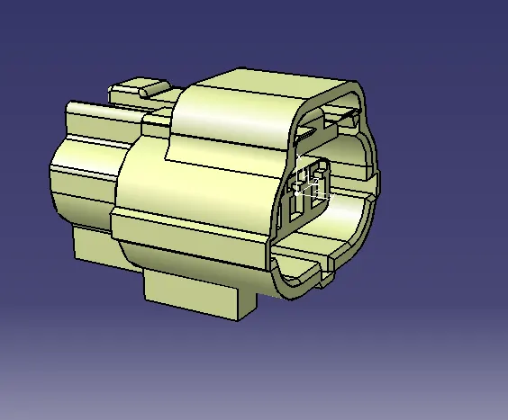
- and create the point for the bundle entry segment in the connector .
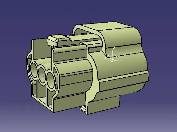
- then in electrical work bench define the part as the connector.
- and the define the no. of terminals in the connector. example :in this connector, the terminal no. is given the part no itself i.e c-1-174357-2-e-3d where 3 is the no. of terminals.
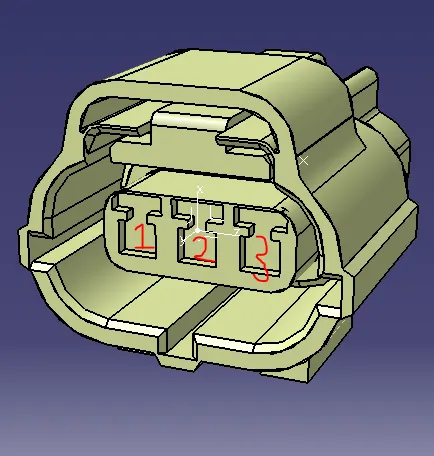
- if it is not mentioned in the part no. or if there any doubt in the chosing the no. of termials, check the no. terminals in the connector connection point. refer the above image.
- after defining as the connector, make define of connector connection point.
- define the appropriate axis system, face to coincide and oreintation of the connector in connector connection point.
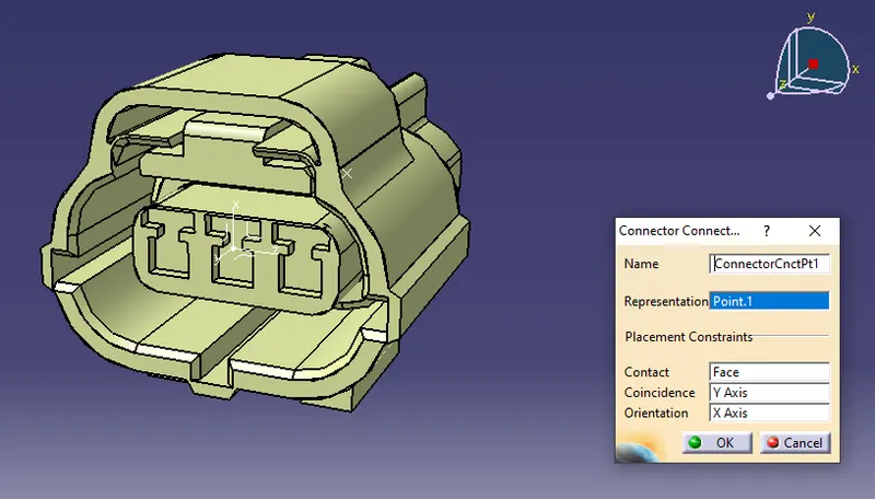
- after that define the bundle entry point for the connector.
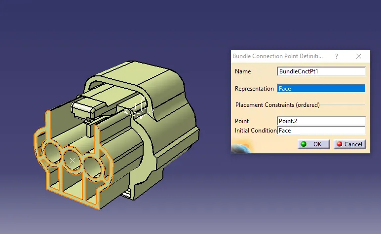
- if it is a female connector, it has a mounting definition which tends to mount on the external environment.
- to define the mounting clip, create the requied geometry axis for the cavity.
- and in electrical workbench, define the cavity point by giving the axis point and the orientation of the mounting clip.
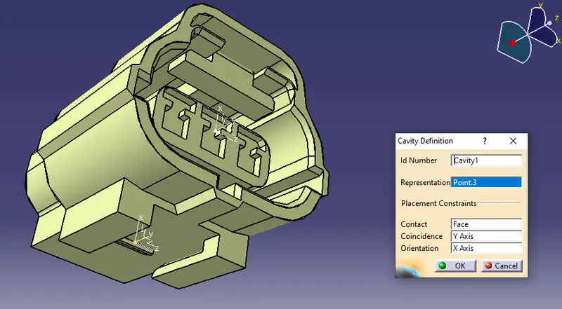
- similarly define it for all the 10 connectors. and save in the separate catague named as connectors
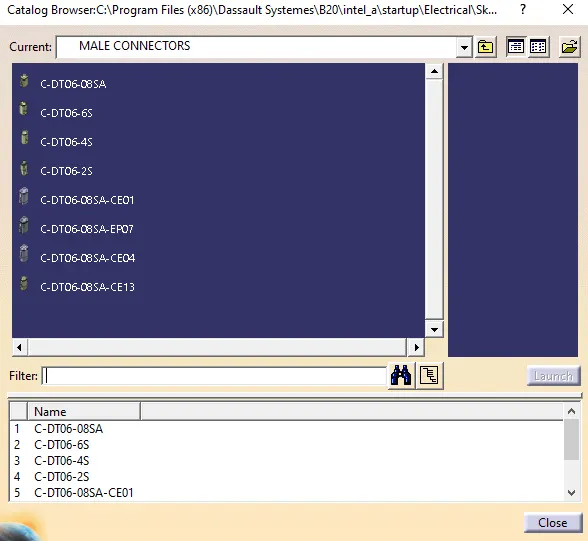
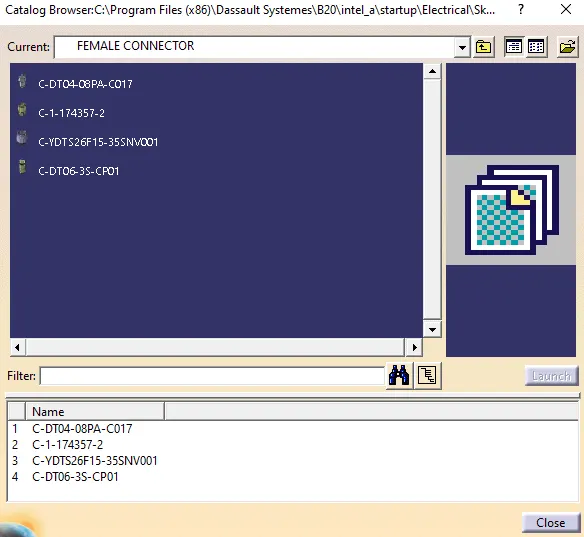
STEP 2 : WIRING HARNESS ROUTING LAYOUT
- for an easy and accurate connector position, use the predefined sketch for assemble the connector (Eg : HARNESS A)
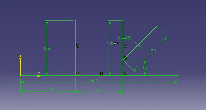
- and open a new product and insert all the required connectors in the product file, then assembly the connector accordingly to the given harness A layout.
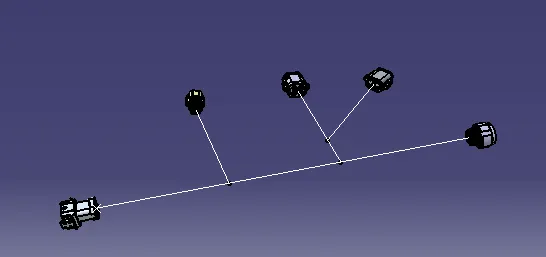
STEP 3 : ELECTRICAL HARNESS ASSEMBLY
- then open the electrical harness assembly, define the product file as geometrical bundle.
- click on multi branchable icon,and define the branchable segments for all the connectors as the required layout.
- bundle dia is assumed as the following.
- the bundle bend radius must be 1.4 - 1.6 of the dia.
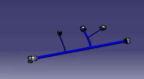
STEP 4 : PROECTIVE COVERING
there are two types of protective coverings are used in the automotive wiring harness.
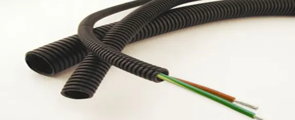
- corrugated flexible tubes
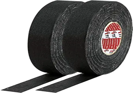
- insulation tapes
- CORRUGATED FLEXIBLE TUBES :
COT tubes are made of plastic material and easily flexible. this helps the wiring harness from thermal and physical damages and also gives the better asthetic apperance of the harness. whereas the yellow COT tubes are used for the high voltage safety systems such as air bags.
- INSULATION TAPES :
they are made up of pvcor cotton polymer material. The main purpose of the insulation tape is to align the wiring harness in the systematic arrange so that it can form a circular bundle. The cotton tapping application is mainly they are demanded in high temperature like engine area. Cotton tapping have very high temperature resistance.

PVC TAPE
COTTON TAPE
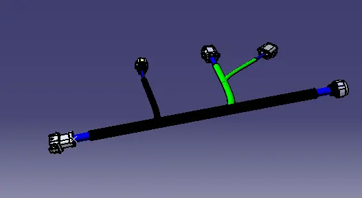
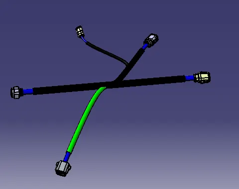
- In the given wiring harness layout, the branch which is black colour protection covering is corrugated tubes and where as green colour protective covering indicates the pvc tapes.
- similar steps do it for harness B
STEP 5 : BUNDLE WARNING CHECKING
- for the study purpose, predominadly changed the connector location to give the error.
- now as the images shows that the minimum bend radius must be 7.5 mm but the computed bend radius is 2.5 mm .for this instance the bundle warning is indicataed with the red colour if there is any error in the bundle. and alo it refects in the family tree.
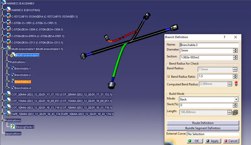
- to resolve this error, the connector position must be aligned to get match the bending radius value or to adjust the slack value.
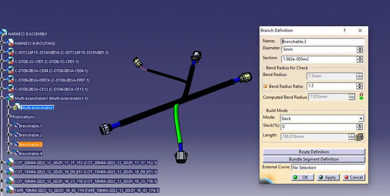
- now the connector position is aligned and bundle warning indicated with green, this shows there is no error in the bundle.
STEP 6 : BUNDLE CONTINUITY CHECK
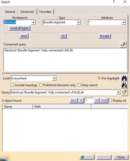
- this is used to show that the all the connectors are connect with the bundle and have a well defined harness assembly.
- for checking the bundle continuity check.
- go to edit - search - advanced dialog box
- in that select the segment you what to check.
- and click on the search option. and it will give the results
STEP 7 : INTERCONNECTION OF HARNESS A AND B
- create a new product
- and both harness A and B
- go to electrical assembly work bench
- select connect option with appropriate harness installation
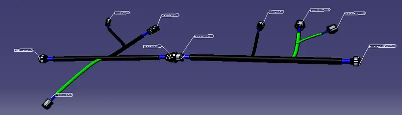
STEP 8 : ANNOTATION
- It is helpful to specify any notes on the connector
- used in the design review stage - to identify the connector specifcation, voltage across the bundle , type of mounting clip etc..
- to add the annotation , go to assembly design - click on view creation icon
- view creation icon helps to create the annotation plane
- and after that we can add the annotation to all the connectos in the same plane
CONCLUSION
The wiring harness routing has been defined and protective covering has been installed with the given layout and connectors where as the bundle dia is keet as an assumption and the file has been converted into IGS format.