Section Modulus calculation and optimization
MOMENT OF INERTIA :
It is also known as the second moment of area where shows the efficieny of the cross sectional area to with stand the load.
symbol - I
unit - mm^4
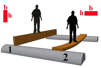
the above fig shows that the beam 2 has been tends to more bending deflection than the beam 1, but both the beams are having same cross sectional area.
this is because when the load acts perpendicular to the beam which has larger area and distance from neutral axis , has a better moment of inertia. when the moment of inertia is more , there will be less bending deflection will occured or in other words more force is required to bend the beam if moment of inertia is more.
EXAMPLE :
BEAM 1
B = 100 MM
H = 400 MM
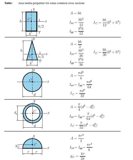
MOMENT OF INERTIA OF AN RECTANGULAR BEAM (I1) = (BH^3)/12
I1 = 533333333.34 MM^4
BEAM 2
B = 400 MM
H = 100 MM
MOMENT OF INERTIA OF AN RECTANGULAR BEAM (I2) = (BH^3)/12
I2 = 33333333.34 MM ^4
This shows that the moment of inertia in I1 is greater than I2
NOTE : The formula of moment of inertia for various cross section will varies accordingly.
NEUTRAL AXIS :
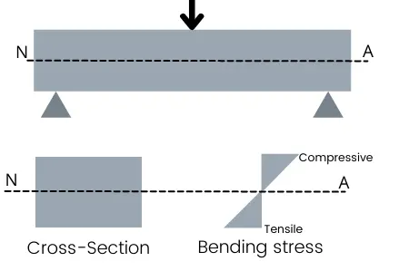
neutral axis of a beam when subjected to bending is the line passing through the fiber beam where there is no longitudinal stress will occure (tensile or compressive) . In other words the elastic neutral axis will lies on the centeroid of the beam.
SECTION MODULUS (ELASTIC) :
In general , it is used to find the yeild point of the materials
where the section modulus is defined as the ratio of moment of inertia to the distance from the neutal axis to the extreme end of the object.
S = I/Y
unit = mm^3
Where,
S = Section Modulus
I = Moment of Inertia
y = distance between the neutral axis and the extreme end of the object
SECTION MODULUS OF THE ORGINAL HOOD DESIGN :
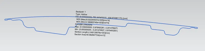
the X directional sectional curve of hood outer panel and the hood inner panel is taken and made into a single closed curve, this curve feature takes into the analysis of sectional modulus. NX has section inertia analysis to find the moment of inertia of the hood and y is the taken as the centroidal asix of the hood. by having these values when can find the sectional modulus of the hood using the below formula.
Where,
Moment of inertia (M1) = 6.189563749 E^+3 mm^4
distance between the neutral axis and the extreme end of the object = 240.4951 mm
therefore,
section modulus (S1) = M1/Y
= 25.736 mm^3
SECTION MODULUS OF THE MODIFIED HOOD DESIGN :
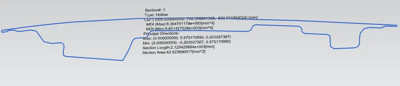
the modifications are done the area of striker and hinge embosses , where the depth of the embosses has been increased to 7.5 mm . by considering those values we can find the sectional modulus of the modified hood.
where,
Moment of inertia (M2) = 9.651427038 E^+3 mm^4
distance between the neutral axis and the extreme end of the object = 240.4951 mm
therefore,
section modulus (S2) = M2/Y
= 40.131 mm^3
CONCLUSION :
when increasing cross section, the distance from the edge of the hood to the neutral axis in the modified hood has been increased . so it gives the better moment of inertia . if the moment of inertai is higher , the valve of sectional modulus also becomes higher. this gives the better results during the design consideration of the hood.
the emboss depth incresed to 7.5 mm has given a better difference of 14.395 mm^3 of sectional modulus in that hood. hence modified hood gave us the better results in analysing the sectional modulus.
therefore when the sectional modulus of the cross sectional element or a beam ( i.e hood ) is increased , there can be an increase in strenght and stiffness to that element or beam.