Week 8 - Challenge 4 - Coin Holder Design
DESIGN DRAFT ANALYSIS COIN HOLDER
AIM:-
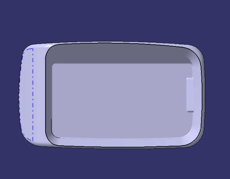
To make a solid model from the given class a surface an making a draft analysis using CATIA.
INTRODUCTION
CALSS A SURFACE:- A surface created by the designer and handed to the plastic modeller to
work on It is the aesthetic surface as well as the outermost surface.
CLASS B SURFACE: A surface with a thickness less than a specific value from the class- A
surface is a surface of class B. This is the surface of a model that comprises engineering
characteristics.
CLASS C SURFACE:- The Surface joining class A and B surface to form a solid model.
METHODOLOGY:
The concepts used in the model are as follows:
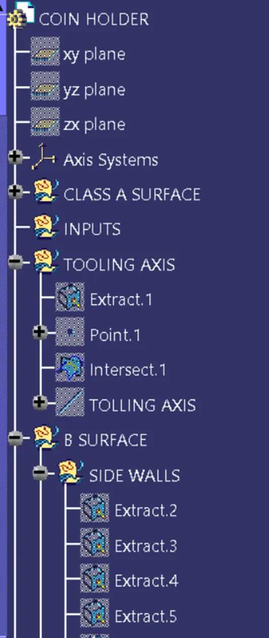
- Tooling axis
- Draft analysis
- Class-B surface
- Class-C surface
- Making a solid model from surface.
CATIA Tools used in this model are:
- Extract
- Un-trim
- Trim
- Extrapolate
- Offset
- Edge fillet
- Boundary
- Sweep
- Join
- Close (part design)
FOR DRAFT ANALYSIS
- We analyze the model first, then select dummy axes in the x and y directions.
- As we intersected to continue, we saw that the side walls had no draft. As a result, we suppose the axis is parallel to the side walls and normal to the base surface. This will undoubtedly cause issues because a minimum draft must be given.
- Because the class-A surface is created by another designer, only he has the authority to make modifications, we examine it to finish the coin holder for practice.
- Then we to insert to insertà analysisà draft analysis and perform the analysis as normal.
Align the compass and click on the surface; the model is predominantly red, indicating a negative draft with regard to the axis.
- To rectify it as best we could, we moved the compass around until most of the surfaces were green and locked that position.
- After clicking OK, we shift the orientation of the line from the z axis to the compass direction. The axis will adjust itself accordingly.
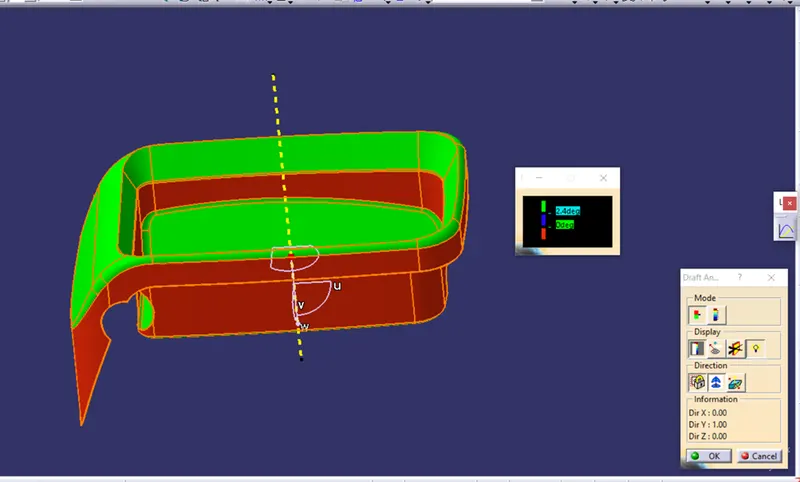
Note Because the side wall does not have a draft, this outcome was predicted, and just a few spots require modification. However, we are continuing to work on the model.
FOR CLASS-B SURFACES
1.We separated the complete model into base, side walls, inner side walls, and outside flange and worked on each one separately.
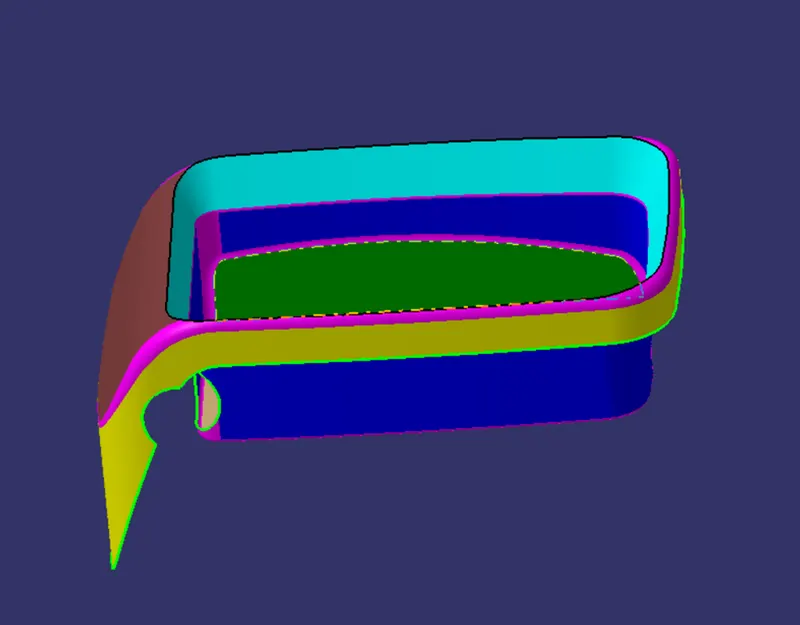
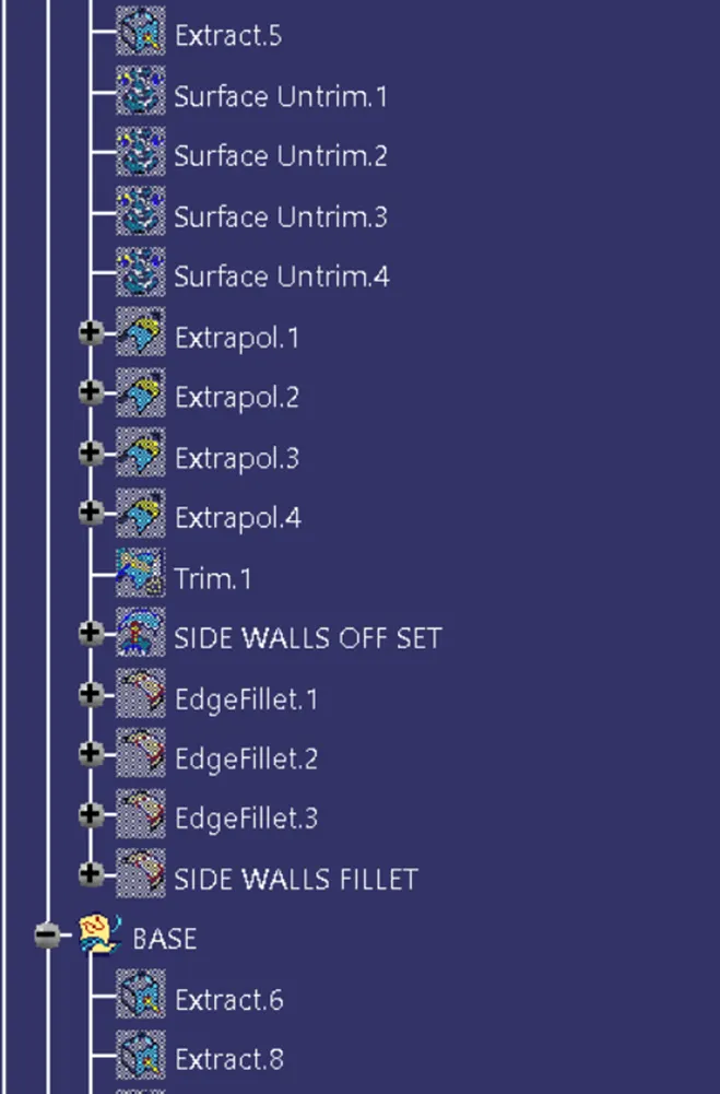
- We use the same process everywhere: extract, un-trim, extrapolate, trim, and offset.
- Begin with the base, then go on to the side walls. To minimize confusion, we trimmed both and combined them into one. The fillet was also provided.
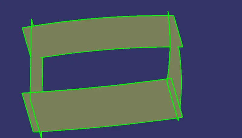
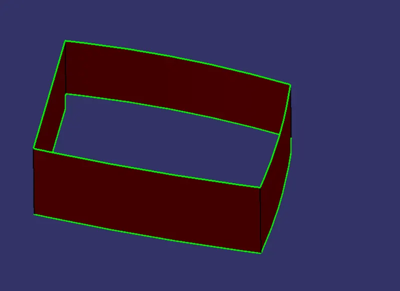
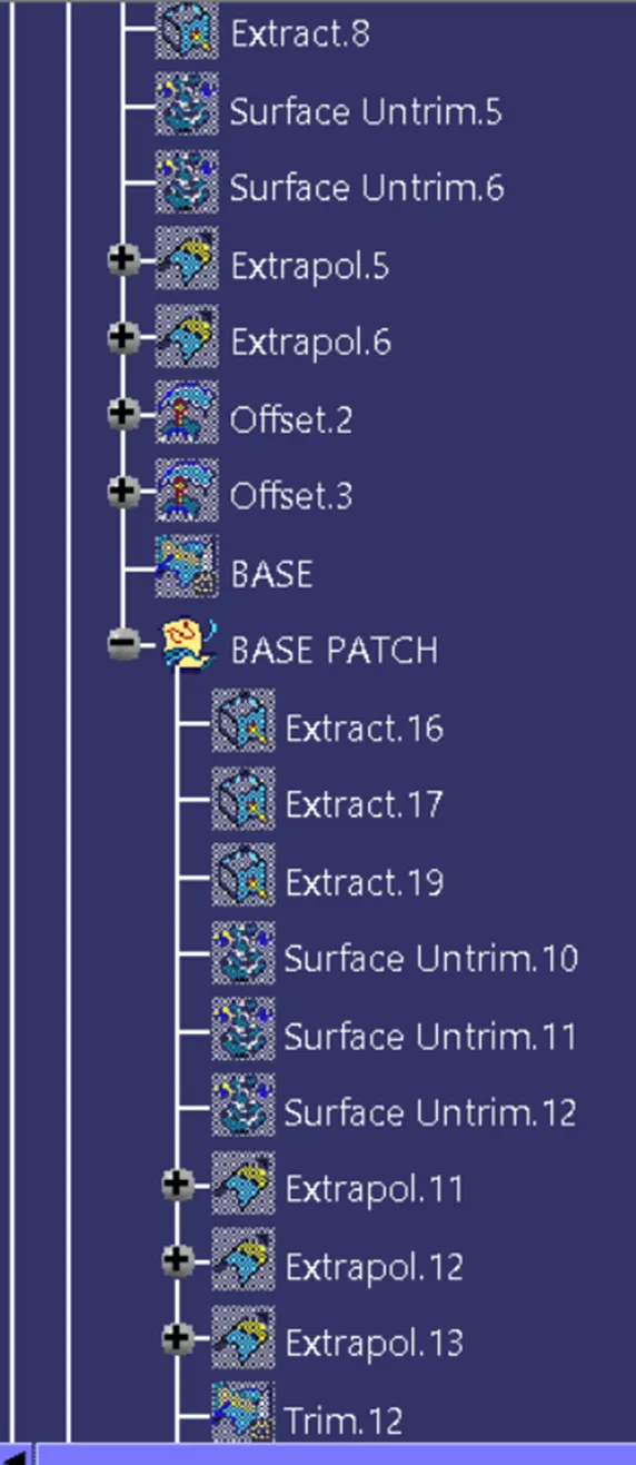
- Next, we will look at the inner side flange. Instead of extract and un-trim, we utilized multi-extract and extrapolated it.
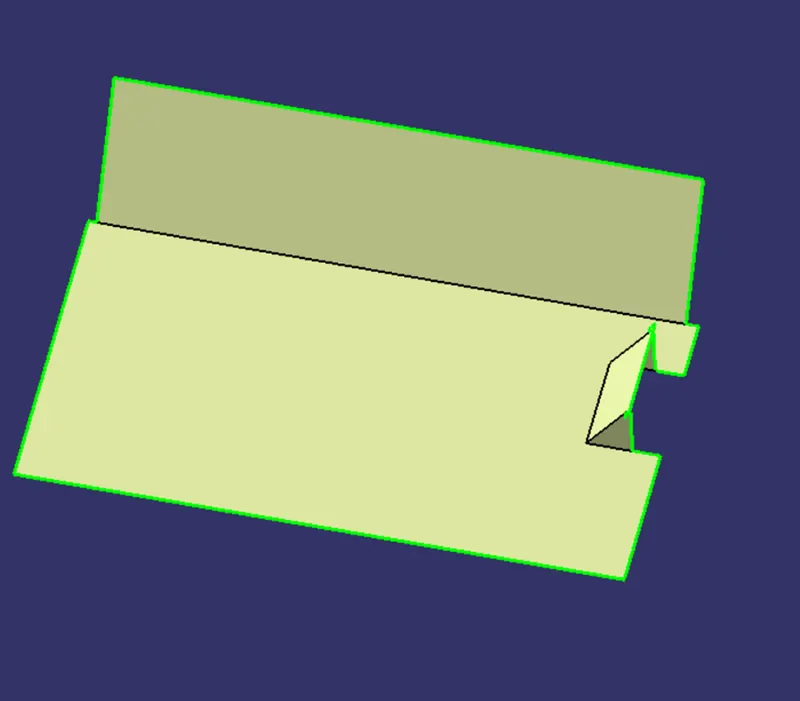
5 We use a similar technique for the outer flange. Following all of this, we have a basic sharp model.
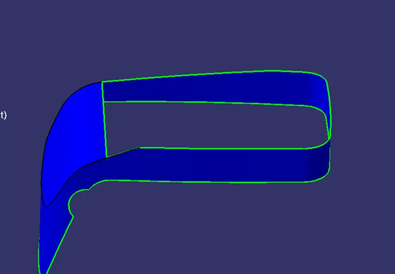
6. We then trim all of them to make them one.
7. we fillet the surface after measuring numerous fillets. Remember to keep the f at a minimum.
FOR CLASS-C SURFACES
- Unlike previous models, we employed a parallel tooling axis in this model. As a result, we are unable to use the 'with draft direction' option under sweep.
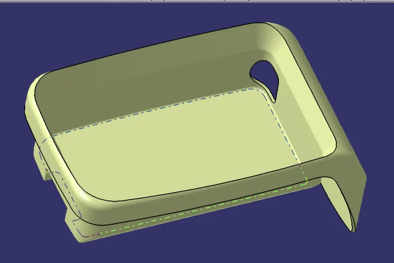
- The C surfaces will be primarily generated in the manner illustrated below
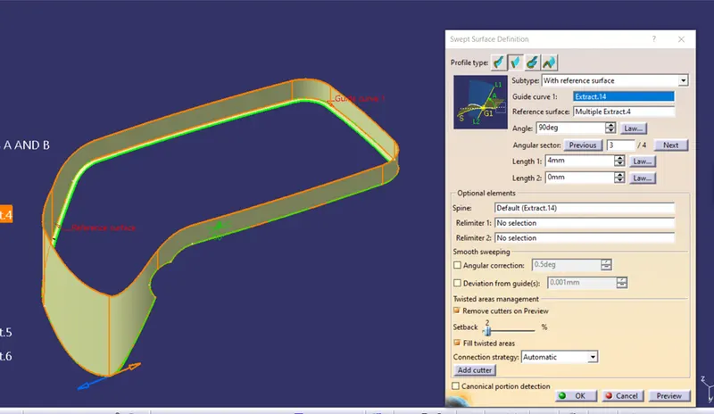

- In this case, we will first obtain the boundary of the class-A surface and then sweep it with the reference surface option.
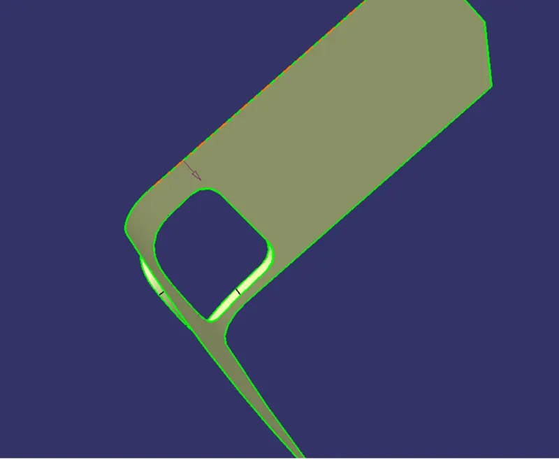
- Similarly, we will obtain the C surface for the hole in order to seal it.
FOR FINAL MODEL
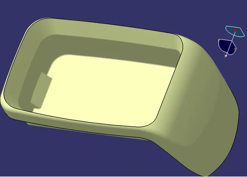
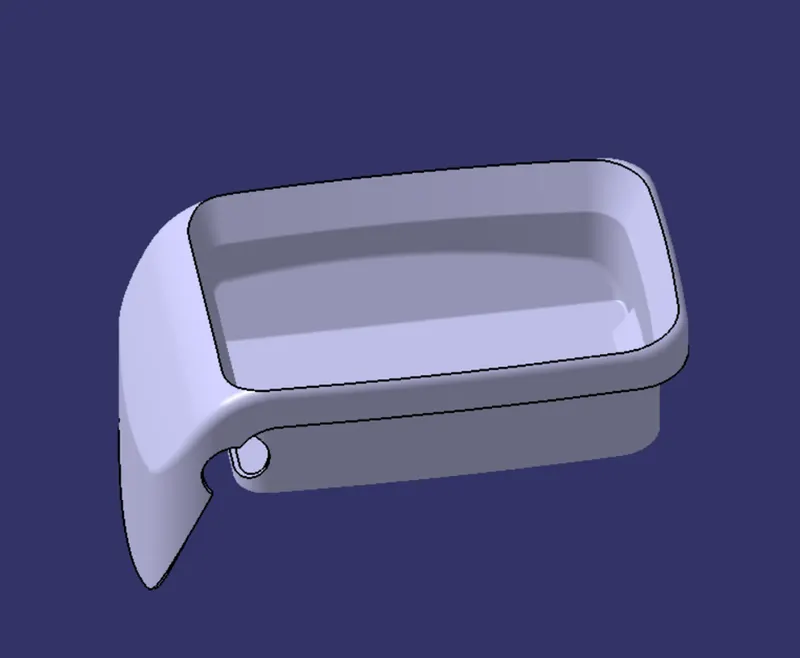
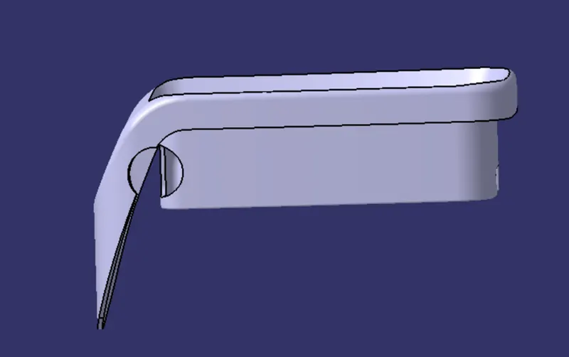
- Join class-A and class-C surfaces together.
- Then join class-B surface to them.
- Go to the part design and close the feature.
- Run draft analysis on the model
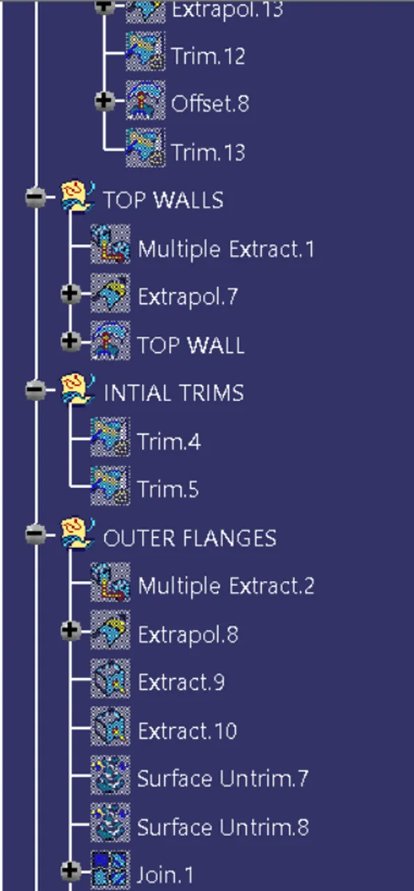
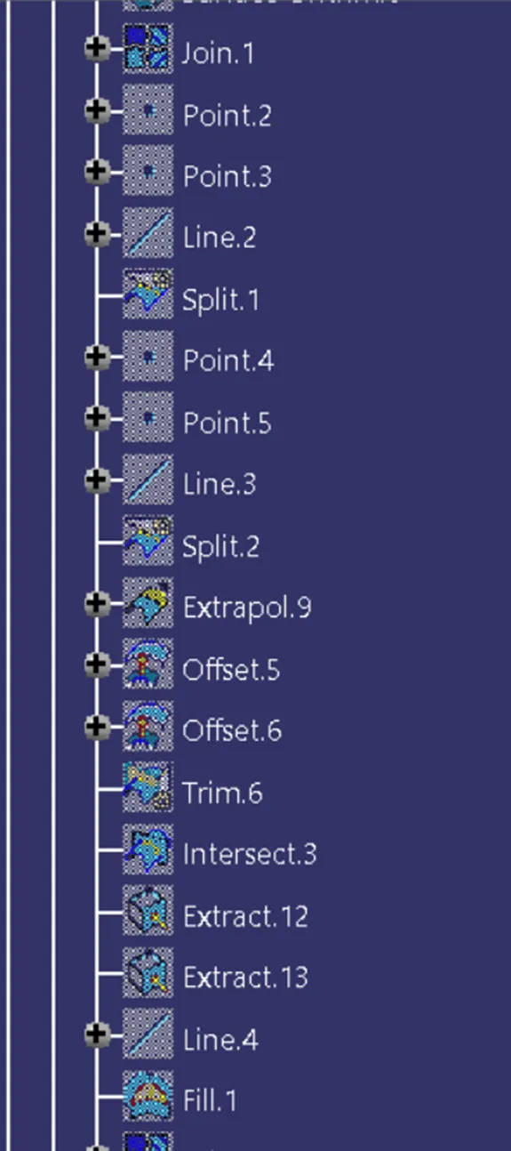
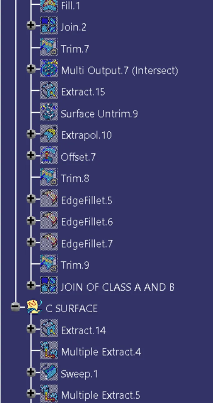
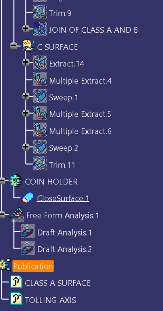
TREE STRUCTURE:
CONCLUSION
Given surface A surface is converted into a solid model with a thickness of 2.5.