Radar Mast & Final Assembly of Yacht

Design and Assembly of Design, Assembly and Photo-Realistic Rendering of an American Predator Yacht
Using SolidWorks.
OBJECTIVE.
The Aim of this project is to design and assembly American Predator Yacht and give a realistic view using Photo 360.
INTRODUCTION:-
SolidWorks is a 3D mechanical CAD program that helps in product development solutions that lets you also conceptualize create, validate, manage and transform your innovative ideas into great product designs
SolidWorks provides a full range of integrated modeling, simulation, visualization, communication, and validation tools that product designers need to develop better products faster and at a lower cost. In addition, its unique capabilities enable the mechanical designer to concentrate on the product design.
Modules in SolidWorks
SolidWorks extends design applications through full integration with best-in-class solutions.
The following modules will be discussed in the concepts
- Sketching
- Part Modelling
- Assembly Modelling
- Surface Modelling
- Sheet Metal Design
- Rendering
- Drawing
This project includes Sketching, Part, Assembly, Surface Modelling and Rendering giving a Real view using Photo view 360.
METHODOLOGY.
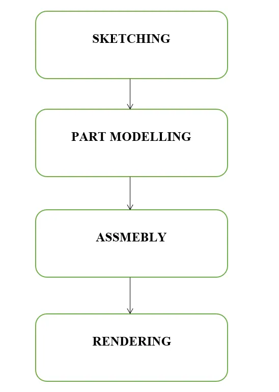
Terms to Beginning SOLIDWORKS: Origin, Plane, Axis, Face, Edge and Vertex
Origin Marked with blue with three axis X,Y and Y . this is the centre point where XYZ planes meet. Origin is shown only when there is a active sketch. Origin represents (0,0,0) co ordinate system
Plane:- Is a construction geometry used for making 2D sketches.
Axis:- Centre straight line used for References.
Face:- particular side of a mould.
Edge:- Intersection of two or more faces or planes.
Vertex- Intersection point of two or more line or faces.
SKETCH CREATION TOOLS
- Sketch Elements: Origin, Plane, Driving dimensions, Driven dimensions, Sketch definitions, Sketch complexity, Where to start a sketch and Sketch snaps.
- Sketch Entities: Inference line, Line, Centerline line, Mid-point line, Circle, Perimeter circle, Arc, Ellipse, Rectangle, Slot, Polygon, Parabola, Spline, Equation driven curve, Point, Text, and grid. Sketch Relations: Co-incident, Co-linear, Concentric, Equal, Fix, Merge, Parallel, Perpendicular, Symmetric and Tangent.
- Dimensions: Smart dimension, Instant 2D, Horizontal dimension, Vertical dimension, locking dimension, Ordinate dimension, Path length dimension, Dimension between two arcs, using centreline for radial and diameter dimensions, and Fully define sketch.
SKETCH EDITING TOOLS
Sketch tools: Construction geometry, Fillet, Chamfer, Offset, convert entities, Trim, Extend, Split, Jog, Mirror, Dynamic Mirror, Move, Copy, Rotate, Scale, Stretch, and Sketch patterns, make path, Close Sketch to Model, Sketch picture, Check Sketch for Feature
Blocks: Make block, edit block, insert block, rebuild block, save block, and explode block.
Sketch diagnosis, sketch expert, Rapid sketch.
Line- Line is the staring command in the sketching tool for making simple line or complex shapes
Circle- circle tool is used to make circular shapes in the drawing plane.
Rectangle – suing this tools four sides shapes are drawn like rectangle, square and different types of parallelogram based on geometric preferences like centre point of sides.
Spline- Smooth curve defined my set of centre points which can be deleted or edited.
Ellipse- sketch a complete ellipse.
Arc- small part of circle.
Mirror Entities Reflected copy of an selected entities about a reference axis or plane
Move entities : Move entities to a desired location.
Liner sketch Patterns- making a copies of sketch in desired direction
Convert Entities :- allow you copy edges or mould to active sketch and they are fully defined.
Intersection Curve: - Intersion cure is a open cureve sketch. Different kinds of intersetions are
A plane and surface or a model face.
Two faces
A surface and a model face.
A plane and the entire part
A surface and the entire part
Trim entities:- Required sketch can be trimmed using Trim entities
Extend Entities: - Enables to extend a line or an arc until next intersection
PART MODELING FEATURES COMMANDS
Feature commands used in this project are as bosses, cuts, and holes. Other sketch-based features such as lofts and sweeps use a profile
Extruded Boss Feature will allow us to take a2D sketch and add thickness and convert it to 3D
Extruded Cut -Itsa tool to remove material by projecting a sketched section
Circular Patters Create copies or instances, in a crcular pattern by giving a circular reference
Linear Patter – Makes copies in a line but desired direction
Curve Driven Pattern - The Curve Driven Pattern tool allows us to create patterns along a planar or 3D curve. To define the patter, we can use
Sketch Driven Pattern - The sketch driven pattern creates copies of existing features and places the wherever we've added a point in a sketch.
Shell- The shell tool hollows out apart, leaves open the faces we select and creates thin-walled features on the remaining faces. I we do not
Edit Feature ~ Edit Feature provides a simple method to change the information used to create a feature. To edit any feature, right-lick the
Revolved Features - Material can be added or removed from a model by using the Revalve command. Revolves add or remove material by
Fillet -Fileting refers to both filets and rounds. The distinction is made by the geometric conditions, not the command isell Files are created
Chamfer tool creates beveled faces. A chamfer, leaflet, is an applied Feature, and does not require you to make a sketch to create the
Section View - Section View cuts the view using one or more section planes.
Mirror - Features can be mirrored about a plane or planar face.
Split - Lines are used to divide model faces into two..
Combine - In a multi body part, we can combine multiple bodies to create a single body. We can only combine bodies contained within one multi body part file. We cannot combine two separate parts.
Dome - It can add one or more domes to the selected planar or non-planar faces. The software calculates the distance using the radius of the arc as a basis for the dome.
Sweeps - Sweeps take a sketch, called a Profile and move it along a Path.
Lofts - Lofts create a solid by connecting a series of loft profiles.
Reference Geometry - Reference geometry defines the shape or form of a surface or a solid. Reference geometry includes items such as planes, axes, coordinate systems, and points.
Project Curve - Select Bi-directional to create a projection that extends on both sides of the sketch. The curve can be used as a path for a sweep.
Composite Curve - We can create composite curves by combining curves, sketch geometry, and model edges into a single curve. Composite curve can be used as a guide curve when creating a loft or a sweep.
Split Line - The Split Line tool is used to project an entity (sketch, solid, surface, face, plane, or surface spline) onto other surfaces or curved/planar faces. We are also able to split faces on multiple bodies with one command.
Assembly Exploded Views - Exploded views are created to make it easier to see how an assembly is put together and to see the parts that are normally hidden from view
PART MODELLING DESCRIPTION
BLUEPRINT
A blueprint is a sketch of a technical drawing. Use print is used to get an idea of dimensions. And model of a product
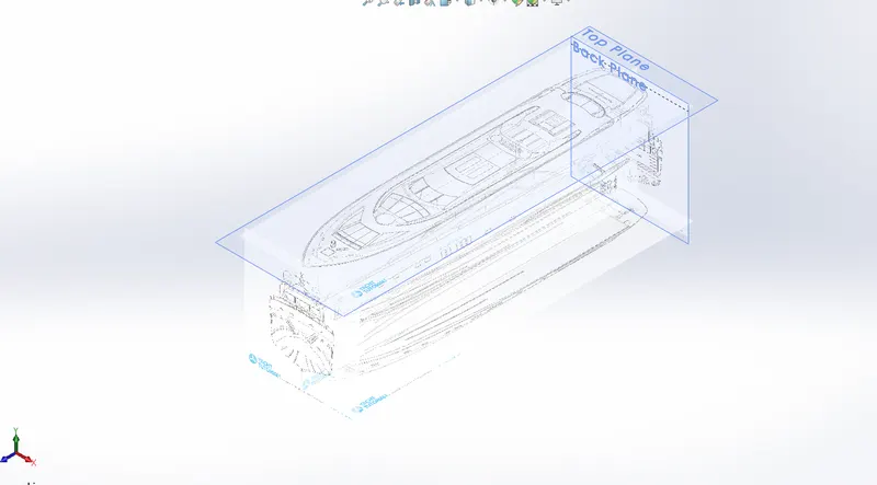
The above shown Blueprint was used to model the Yacht in a fully defined constraints. For setting up the Blueprint the Sketch pictures options were used and placed the different blueprints at the required planes.
1. HULL
A hull is the base part of the yacht. The hull may open at the top (such as a dinghy), or it may be fully or partially covered with a deck. ... The line where the hull meets the water surface is called the waterline.
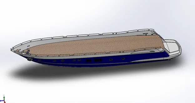
COMMANDS USED TO MODEL
In Sketch
Line
Spline
Circle
Rectangle
Arc
Slot
3-D Sketch
Sketch picture
In Surfaces
Extruded Surface
Revolved Surface
Lofted Surface
Surface Trim
Surface Fill
Surface Knit
Delete Face
In Features
Project Curve
Chamfer
Fillets
Reference Plane
Split
Split Line
Extruded BossBase
Extruded Cut
Mirror
- SUPER STRUCTURE
Super stricture is the top potion of the yacht it adds good look to the yacht and sunny stay in it.
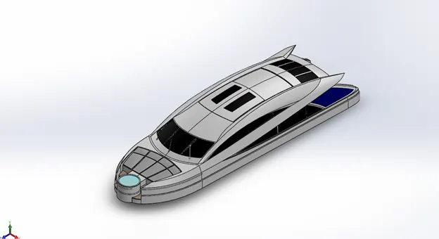
COMMANDS USED TO MODEL
In Sketch
Sketch Picture
3D Sketch
Line
Spline
Circle
Rectangle
Center Point Arc
In Surfaces
Extruded Surface
Swept Surface
Ruled Surface
Knit Surface
Trim Surface
Extend Surface
Filled Surface
Lofted Surface
Revolved Surface
Fillet
Chamfer
In Features
Project Curve
Reference Curve
Convert Entities
Split
Split Line
- PROPELLER
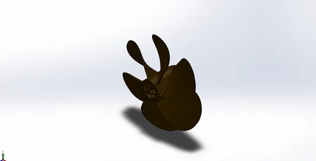
COMMANDS USED TO MODEL
In Sketch
Spline
Circle
Line
In Features
Revolved Boss/Base
Lofted Boss/Base
Extruded Cut
Reference Plane
Circular Pattern
Fillet
MODELLING PROCEDURE
The centre part of the Propeller was sketched and revolved using Revolved Boss/Base.
Then the Blades were created using the Reference Plane, Lofted Boss/Base and Fillet.
- GARAGE DOOR.
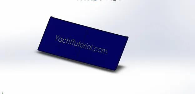
A garage door is a large door for parking space on a garage that opens either manually or by an electric motor
COMMANDS USED TO MODEL
In Sketch
Line
Spline
Circle
Text
In Features
Extruded Cut
Reference Plane
Fillet
Shell
Mirror
MODELLING PROCEDURE
The solid body split while creating the Hull was imported to model the Garage Door.
By using the Extruded Cut the Chamfered face for the door was created.
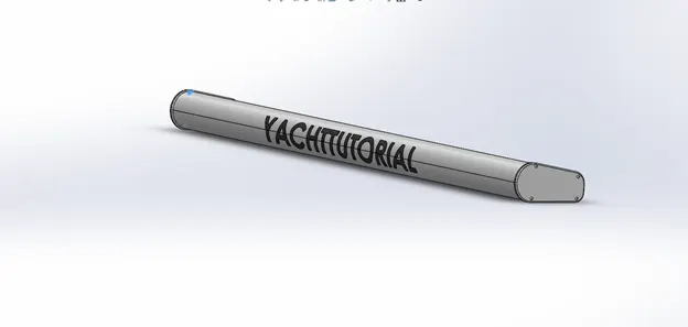
- RADAR
COMMANDS USED TO MODEL
In Sketch
Line
Text
Circle
Point
In Features
Extruded Boss/Base
Extruded Cut
Sketch Pattern
Fillet
Mirror
Split Line
MODELLING PROCEDURE
By drawing the required sketch the body of the Radar was created using Extruded Boss/Base.
By using the Sketch Pattern the four Dotted holes were created using Extruded Boss/Base and Extruded Cut.
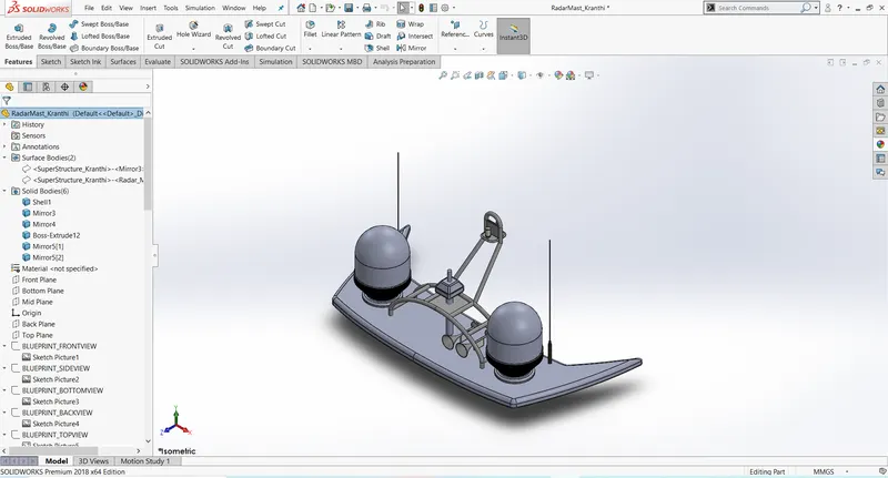
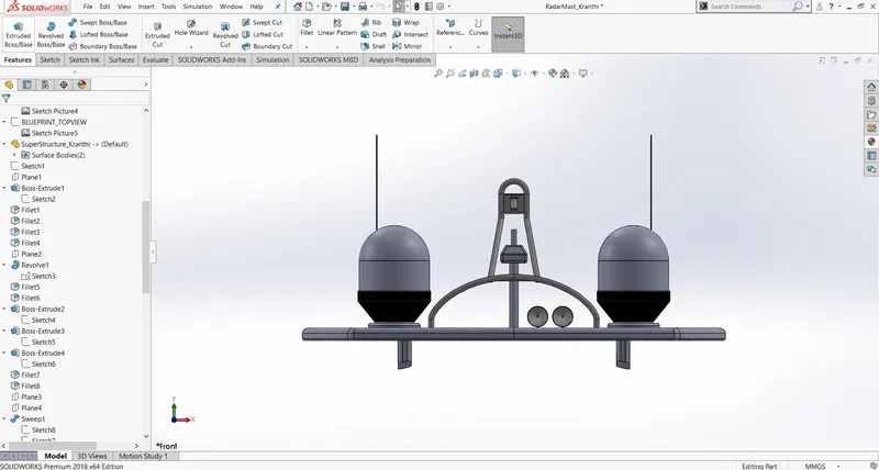
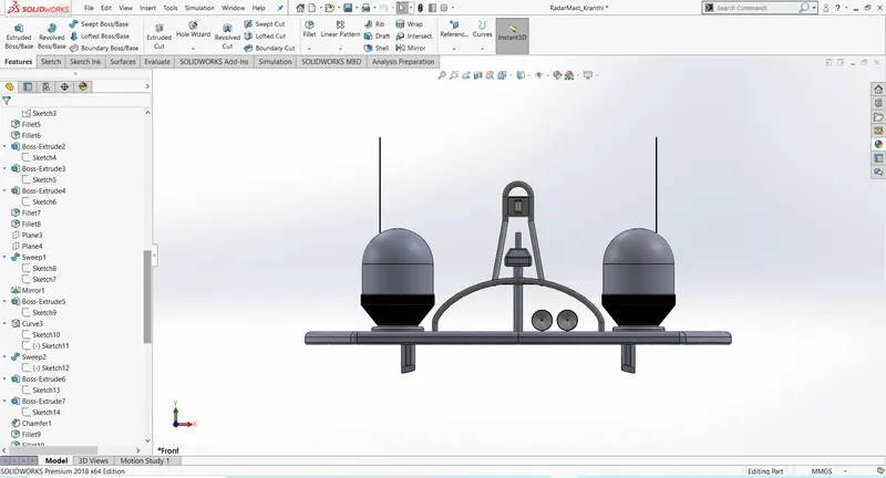
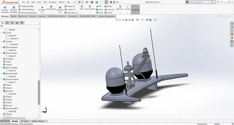
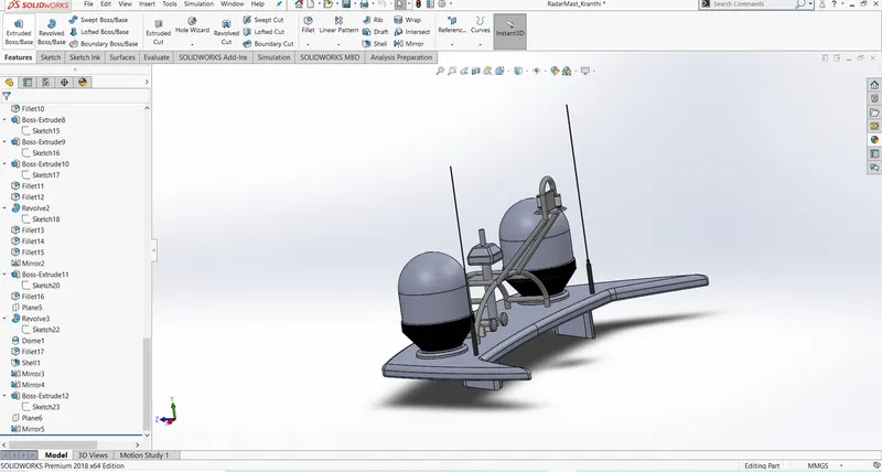
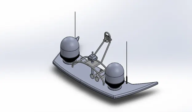
- RADARMAST
COMMANDS USED TO MODEL
In Sketch
Sketch Picture
Line
Spline
Rectangle
Arcs
In Feature
Extruded Boss/Base
Lofted Boss/Base
Revolved Boss/Base
Swept Boss/Base
Reference Plane
Projected Curve
Fillet
Mirror
Dome
Shell
MODELLING PROCEDURE
The first half of the radar was modelled using blueprints, while the other half was reflected using the Mirror tool.
The Radar was designed using Extruded Boss/Base and Revolved Boss/Base.
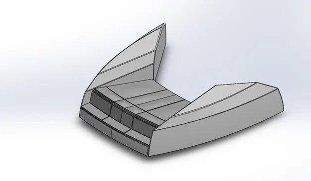
- FRONT SEAT
COMMANDS USED TO MODEL
In Sketch
Sketch Picture
Line
Spline
Circle
Arcs
In Surfaces
Extruded Surface
Lofted Surface
Trim Surface
Filled Surface
Knit Surface
Swept Surface
Revolved Surface
In Features
Extruded Cut
Revolved Boss/Base
Chamfer
Fillet
Mirror
Dome
MODELLING PROCEDURE
The Front seat of the Yacht was also created with the help of Blueprint.
The first half was modelled and the other half was mirrored using Mirror tool.
The front seat was placed before the Superstructure facing the Water Feature of the Superstructure and the back end must be placed on the bow of the Yacht.
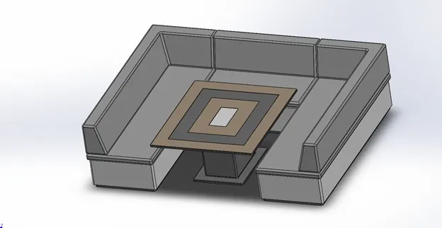
- MIDDLE SEAT
COMMANDS USED TO MODEL
In Sketch
Sketch Picture
Line
Rectangle
In Features
Extruded Boss/Base
Chamfer
Fillet
Mirror
Reference Plane
MODELLING PROCEDURE
The Middle Seat was created using the Extruded Boss/Base and by applying the Chamfers and fillets as required.
- REAR SEAT
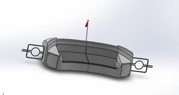
COMMANDS USED TO MODEL
In Sketch
Sketch Picture
Line
Spline
Circle
Arcs
Rectangle
In Surfaces
Swept Surface
Extruded Surface
Off-set Surface
Filled Surface
Knit Surface
Ruled Surface
Lofted Surface
In Features
Reference Plane
Extruded Boss/Base
Revolved Boss/Base
Fillet
Mirror
MODELLING PROCEDURE
The primary body of the Rear Seat was created with Swept Surface and Off-set Surface tools, and the remaining section was trimmed with the Trim Surface tool.
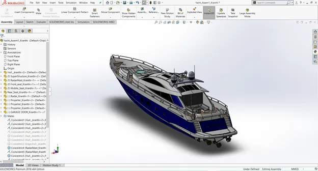
ASSEMBLY
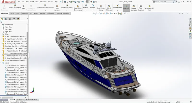
An assembly is a document in which parts, features, and other assemblies (sub-assemblies) are mated together. The parts and subassemblies exist in documents separate from the assembly. An assembly is a document that combines components, features, and additional assemblies (sub-assemblies). Parts and subassemblies are documented separately from the assembly.
RENDERING
Rendering of the Solidworks model is done using PhotoView 360 and Solidworks Visualize.
PhotoView 360
.SOLIDWORKS includes PhotoView 360 as a visualisation and rendering solution. It may be used to exhibit our concepts by providing a highly interactive environment for examining designs as well as producing photo-realistic representations.
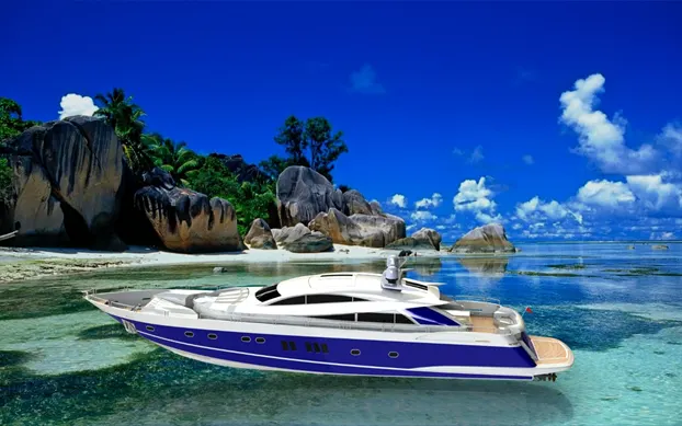
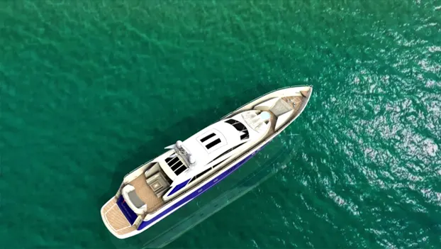
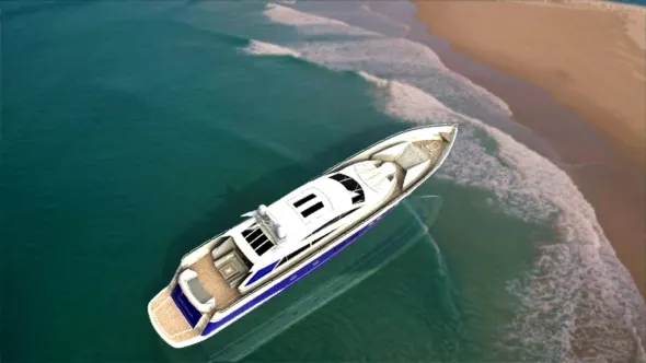
My Solidworks is crashing while rendering so I put in only 3 images.
CONCLUSION
Thus, the project Design, Assembly, and Photo-Realistic Rendering of an American Predator Yacht was successfully Modeled and Rendered.