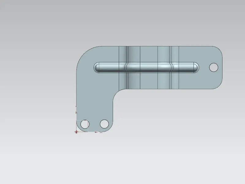
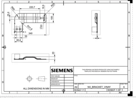
Advanced Sheet Metal Design Using NX Cad Challenge_6_Bracket
BRACKET DESIGN IN NX CAD
Design methodology:-
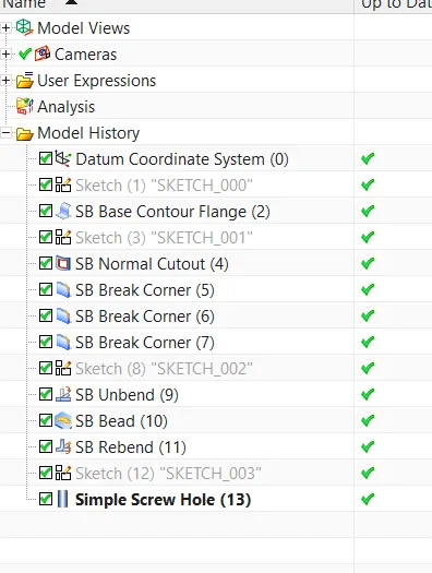
- In NX cad, create a new sheet metal part.
- Create a contour flange using sketch and the parameters provided.
- Using the given dimensions, cut the body as normal.
- Provide some break corners with the necessary dimensions.
- Unbend the model and draw a bead using a line sketch.
- Make some holes according to the specifications.
- Modify the model
- If necessary, use a draught tool to create a drawing sheet for the customer's understanding.
As a result, the model is complete.
Tab:
A tab is a standard extrude feature with a thickness. It will be employed in the extrusion of closed diagrams and linear faces.
Flange: A flange is used to extend the edge of material at the required angle and length.
Dimple:- Lifts a section of the model within a sketch to simulate a stamping tool.
Bead: Beads are similar to dimples. Lifts and movements of the model along with the sketch that simulates a stamping tool.
Bend: We will use the bend feature to bend the sheet metal at an angle.
Unbend&rebend:- After using the bend feature, we need to unbend the sheet metal if we want to create more features on the model.
Unbend&rebend:- After using the bend feature, we need to unbend the sheetmetal if we want to create more features on the model.
Rebend is a feature that is used after an existing model has been unbending to create the final model after all of the features or modeling has been completed.
Normal cutout: A normal cutout is used to create a hole in a flat or normal face using various closed drawings.
Convert from solid body to sheet metal: This feature converts the solid body into a sheet metal part. Converting this model will make the process simple and convenient.
FLAT PATTERN: A flat pattern is created by forming a sheet metal part into a flat pattern.
Contour flange:- A contour flange is a type of flange that is created by sketches on the model based on the model's shape requirements.
HOLE:- This feature is used to create a hole in the model based on the specifications.
Front View,
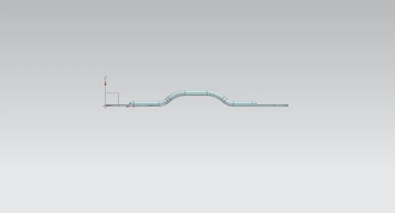
Side View,
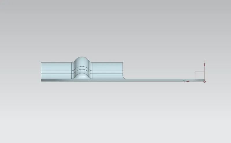
Isometric View
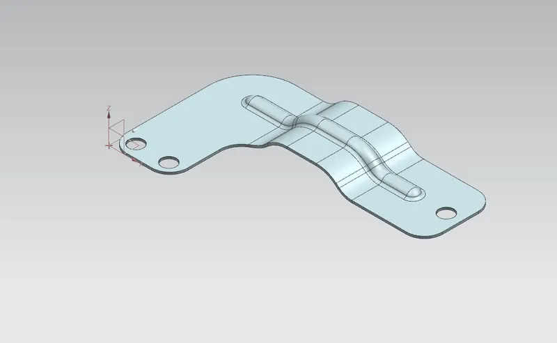
Top View