Week 9 - Project - Master Section Development
TO DESGIN B-PILLAR FROM MASTERSECTION
AIM:
To create a closed body by designing a B pillar with the provided mastersection and following to the design requirements and thickness.
INTRODUCTION:
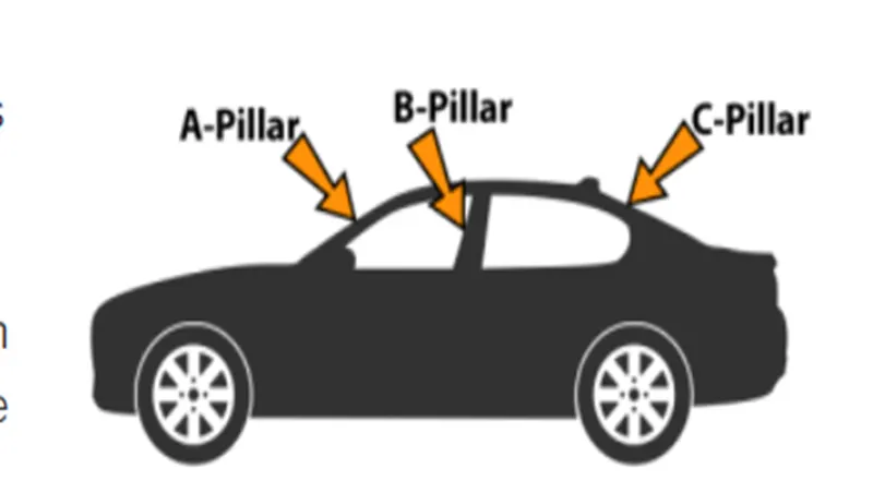
The B-pillar is the post that connects the roof to the body of an automobile and is located between the front and back seat doors. On a normal car, it can alternatively be defined as the vertical roof support structure placed between the front and rear doors. It corresponds to the A pillar, which is positioned on either side of the front windshield, and the C pillar, which is located on either side of the back window in a standard sedan car.
AIM:
To create a closed body by designing a B pillar with the provided mastersection and following to the design requirements and thickness.
INTRODUCTION:
The B-pillar is the post that connects the roof to the body of an automobile and is located between the front and back seat doors. On a normal car, it can alternatively be defined as the vertical roof support structure placed between the front and rear doors. It corresponds to the A pillar, which is positioned on either side of the front windshield, and the C pillar, which is located on either side of the back window in a standard sedan car.
MASTER SECTION:
After technical (Styling, Concept, or Class-A) surfaces, master sections serve as design requirements guides that determine component packaging. The standard workflow for designing and developing interior and exterior automotive trims in OEMs is outlined below.
PROCEDURE:
- Check the supplied Class A surface for geometry issues after importing the model into Catia. If the faces are missing, construct a new face using Catia's multi section tool.
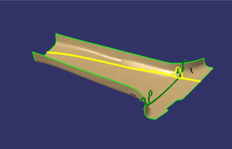
MAIN TOOLING AXIS
Tooling axes for the core and cavity to be constructed later must be created in order to give the drafts for the entire component.
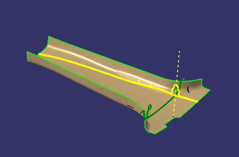
LIFTER TOOLING AXIS
- Create the tooling axis from the specified mastersections using the Line tool's bisecting line option.
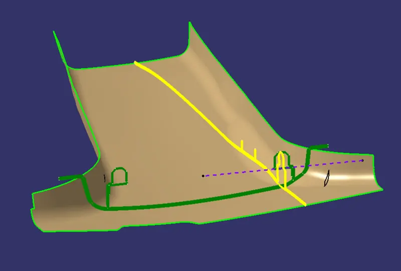
DESIGNING OF FLANGES ANB SURFACE
- Extract the upper two edges of the Class A surface and Master section edges of the flanges and sweep the with reference to the class A surface and trim them
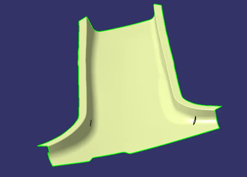
- Off set the Class A with flanges( final trim) to 2mm in upward direction.
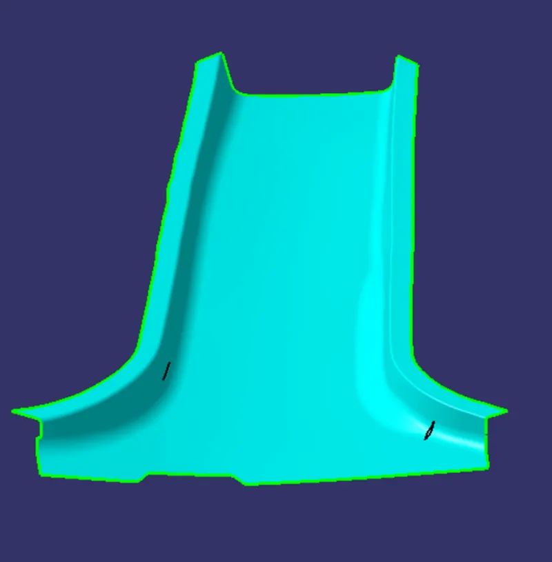
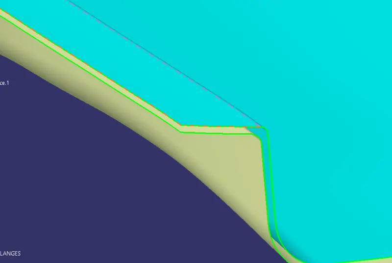
- Extracting surfaces without fillets, untrim and extrapolate the extracted class A surface if necessary, and offsetting the surface to the component thickness specified are the general procedures followed in producing a surface. The surfaces must then be trimmed or split to get the desired form.
- Following the creation of the B surface, the C surface must be devoloped into the Class A surface using the Sweep toolbar, with a minimum draught angle of 3 degrees and no general changes. Only if the Class C surface is parallel to the tooling axis should you pay attention. All of the draught angles must be delivered outside of the part, which means that rather than cutting the material, it must be added.
- Join and trim the C surface all the way along the boundary of class A to make it a single surface.
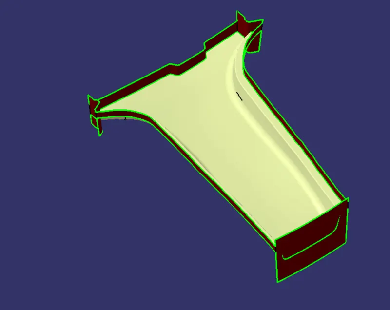
- The class A and class C surfaces must now be trimmed together to produce a single surface, which must then be trimmed with the previously developed Class B surface to obtain the B pillar component.
- After the part is generated, check to see if the boundary is closed or not, then switch to Part design and use the closed volume tool to construct a solid part out of it.
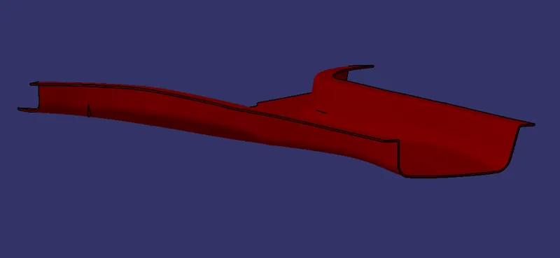
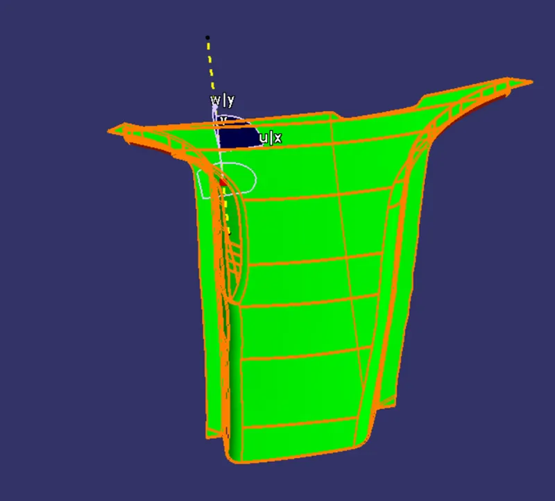
- Check whether the main tooling is clearing all of the parts within the draught after the closed body has been created. The B piller's draught analysis is as follows:
DOG HOUSE WITH LOCATOR AND RIB CREATION:
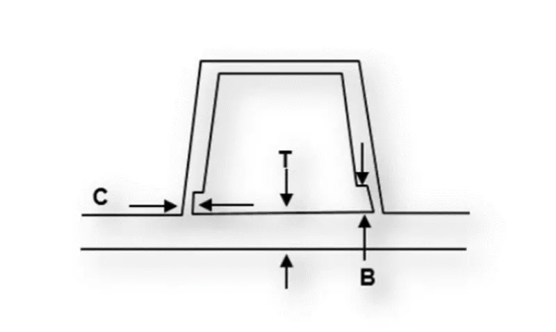
- Proper design regulations or requirements must be followed for the Rib and Dog House, which are listed below.
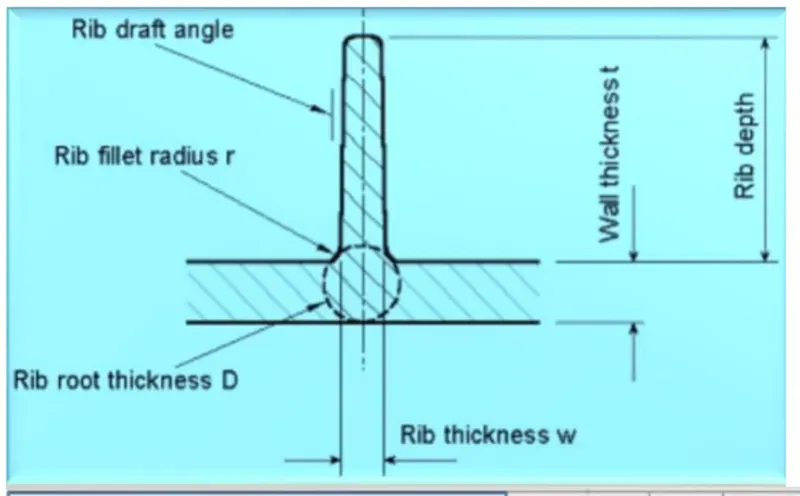
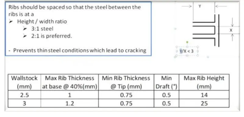
- Minimum height: Less than 6mm causes steel condition.
- 3:1 ratio of steel width to height. But 2:1 is preferred.
- Minimum width:3:1 ratio of steel width to height. But 2:1 is preferred.
- Draft: Minimum 1.5deg.
- In order to avoid sink marks : Height (C) = 40% of nominal thickness. Width (B) = 3.0mm-6.0mm.
- Optimal radius:25mm
- The inner part of the dog house will not be drafted with the main tooling axis after development, thus a side core axis or lifter axis must be developed and a separate draught for the interior of the dog house must be given. The four-way locator may be readily developed using the mastersection sketch as a guide and extruded by adding thickness. A successful locator can be created by using the right chamfer, draught, and fillet radius.
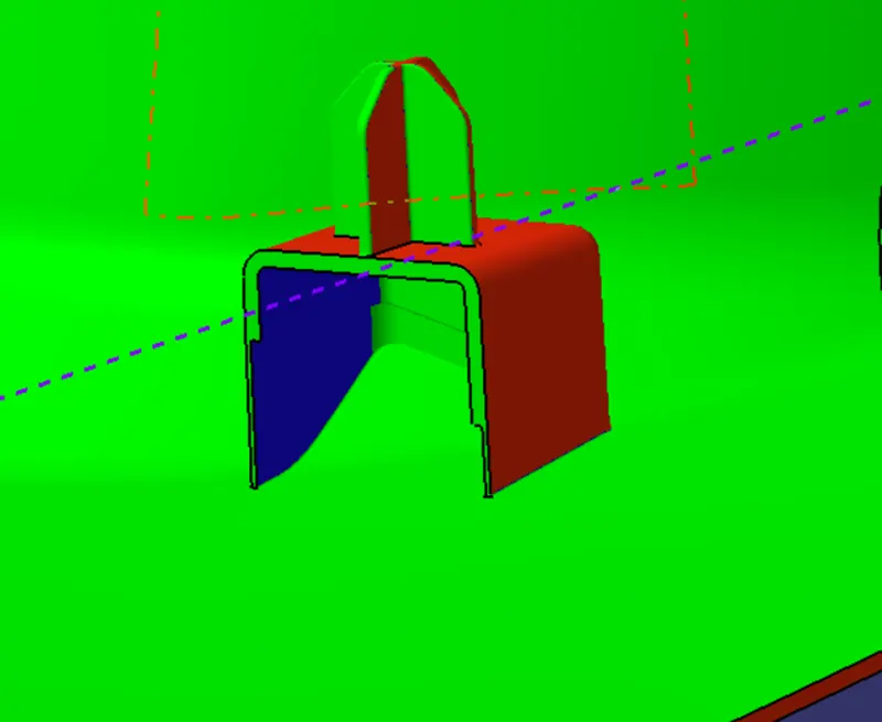
- The following is a draught study for the dog house:
- However, only the Lifter axis will be used to clear the inside walls of the Dog House, as illustrated in the draught study below:
Complete part body Draft analysis with main tolling direction
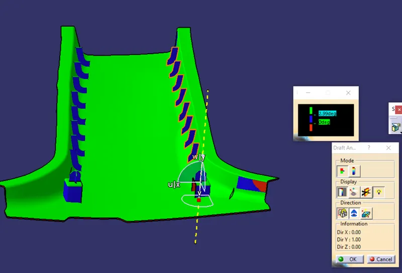
We can see a red shade with right edge of the component that is due to error in Class A surface.
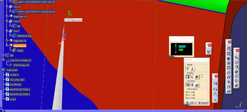
The minimum angle at red location is -0.92.
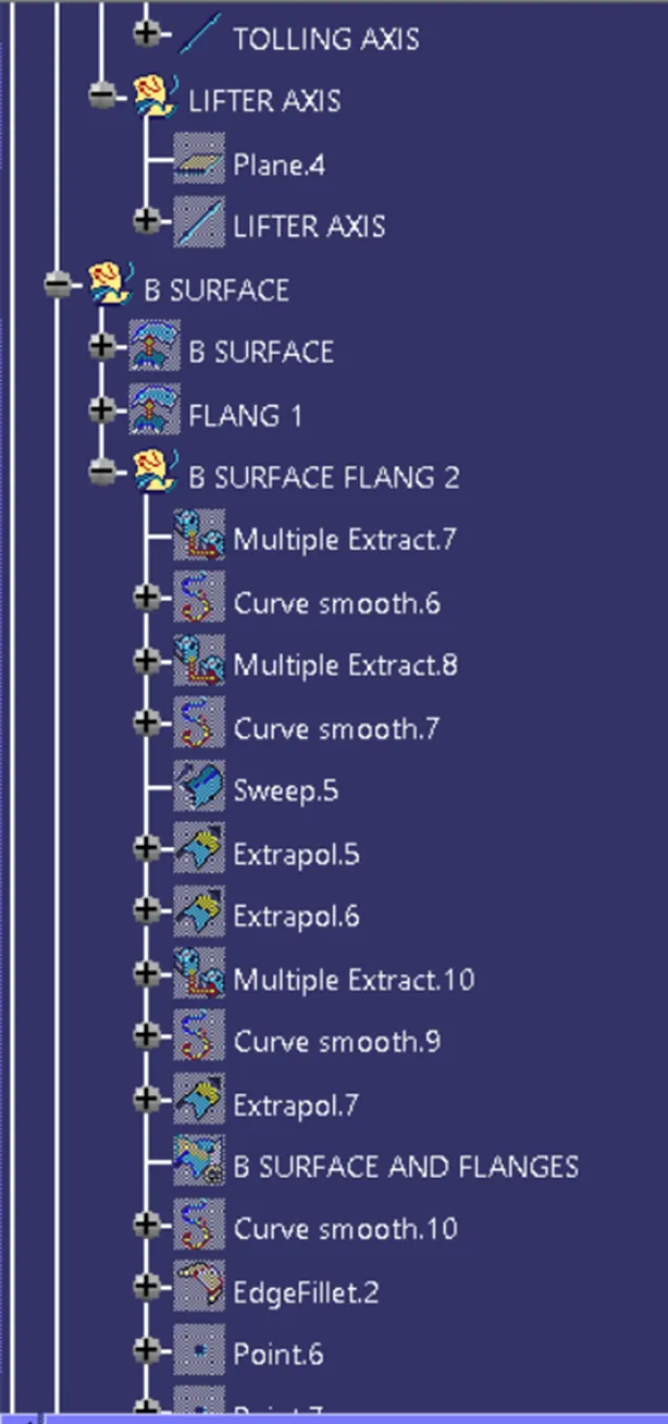
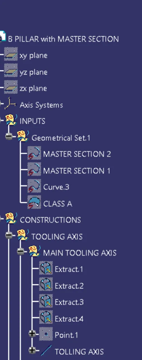
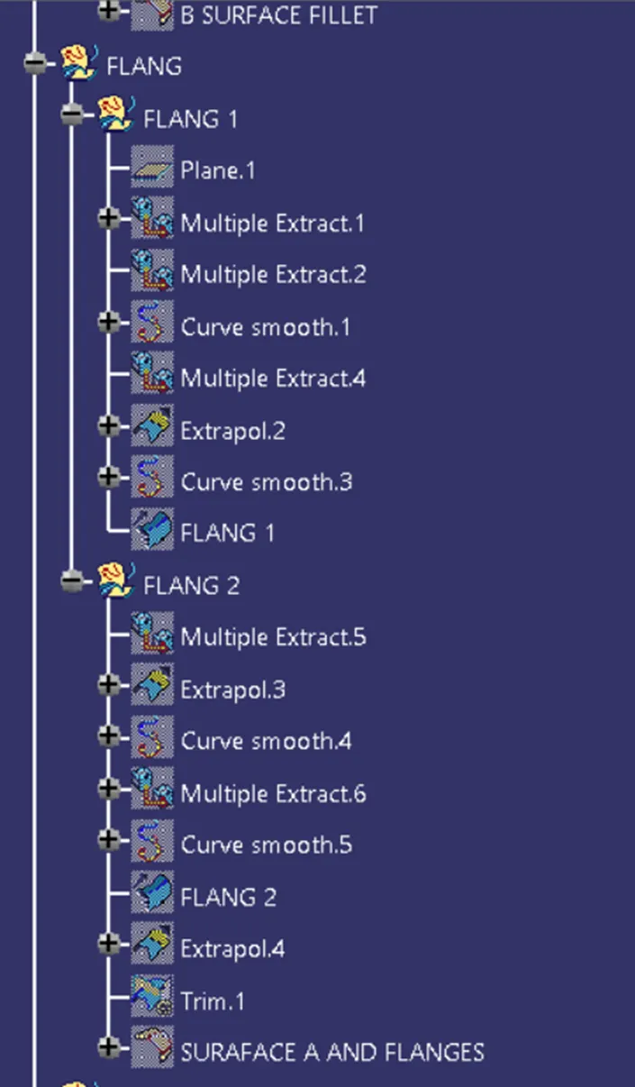
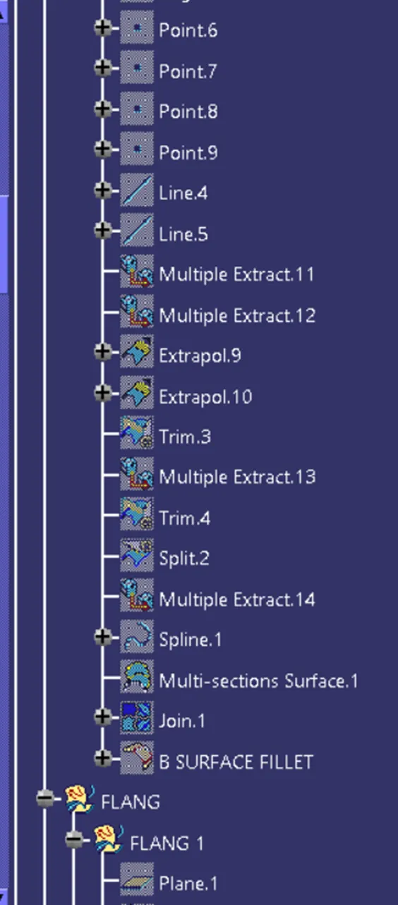
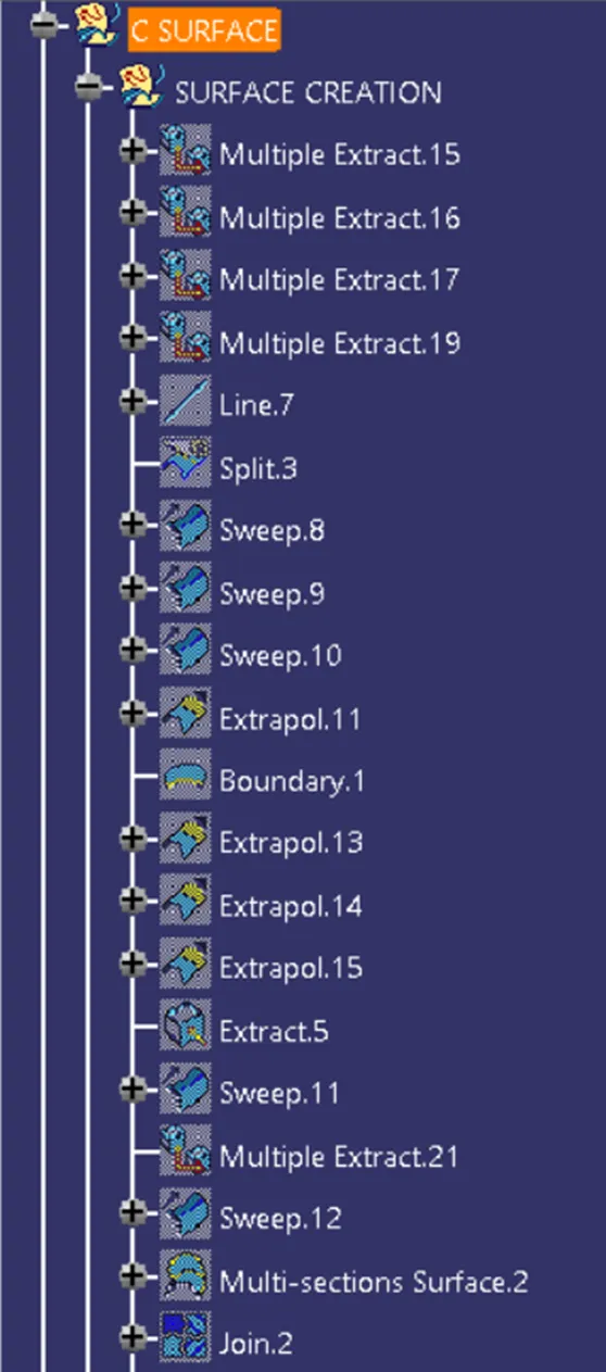
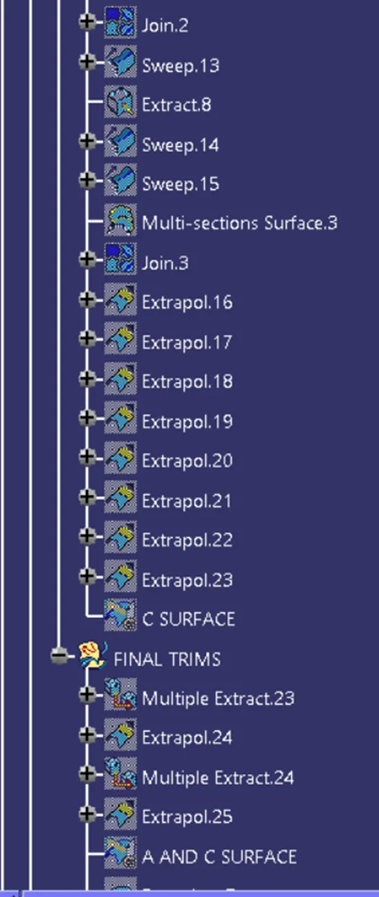
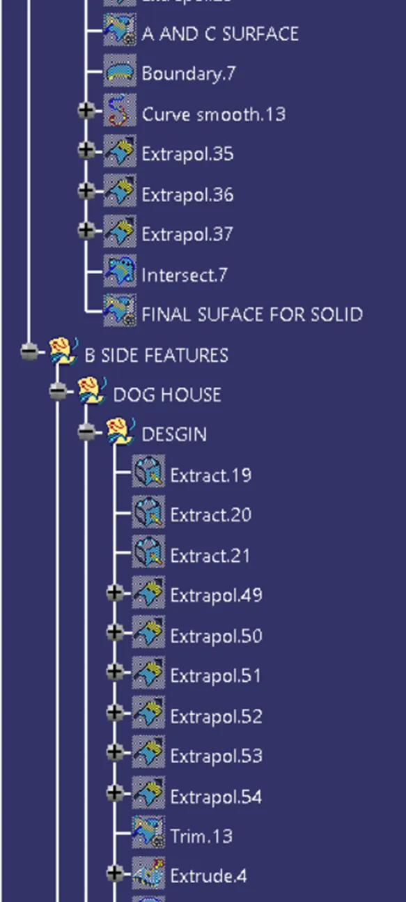
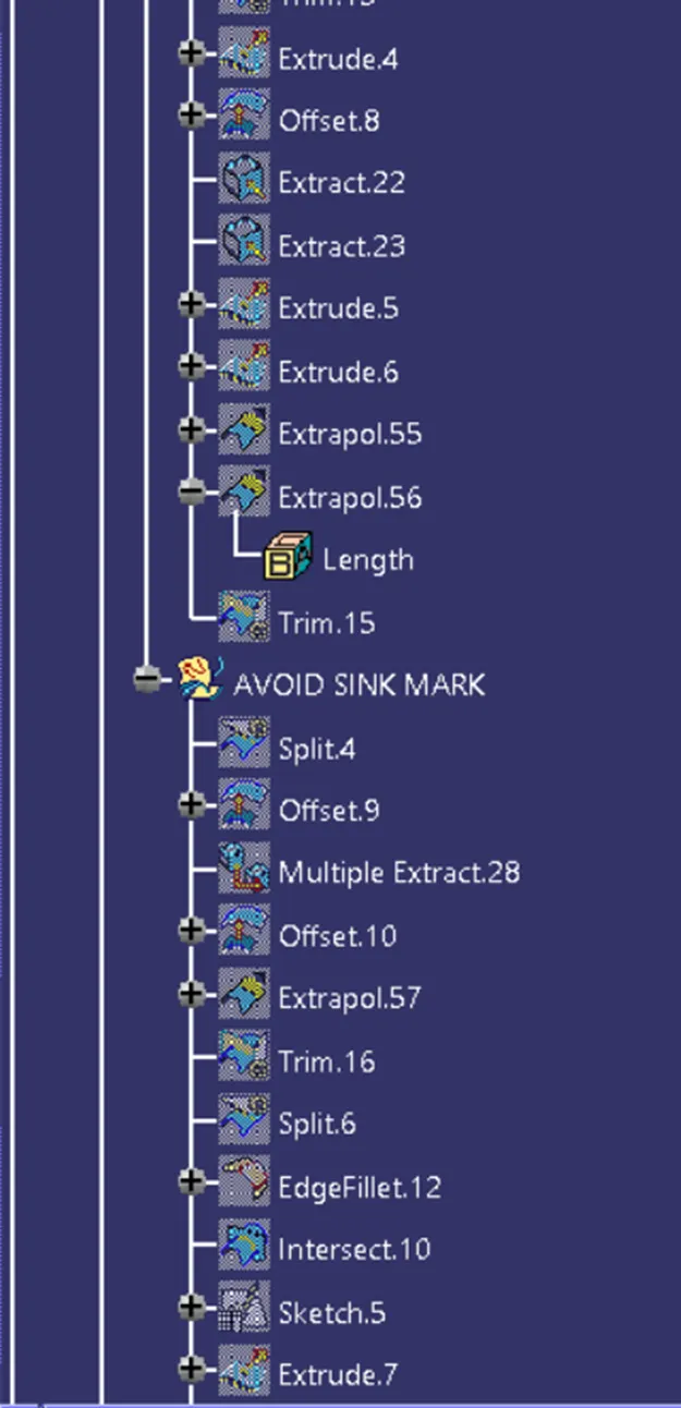
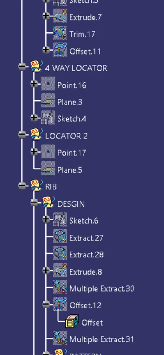
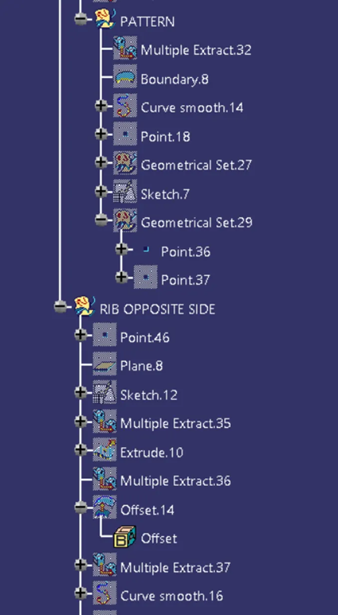
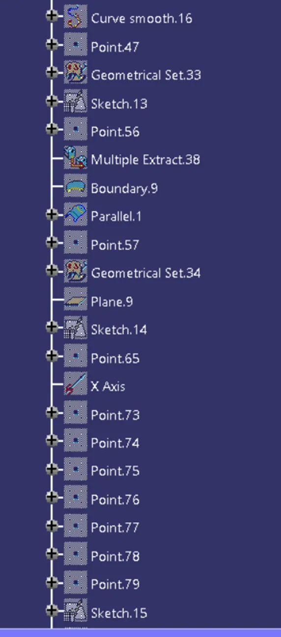
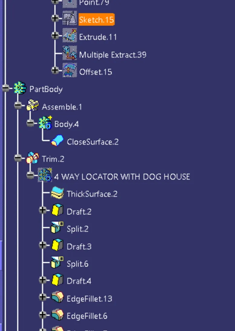
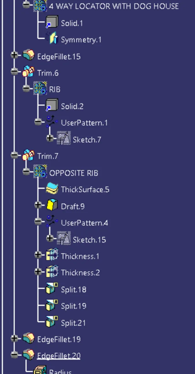
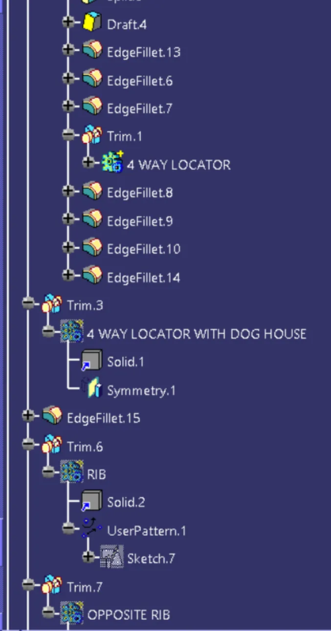
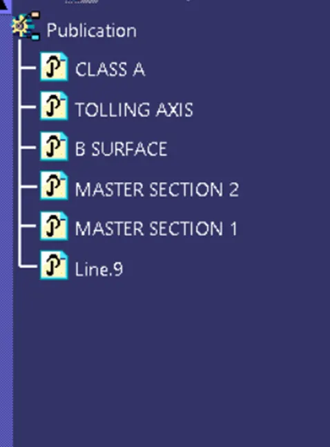
Tree Structure