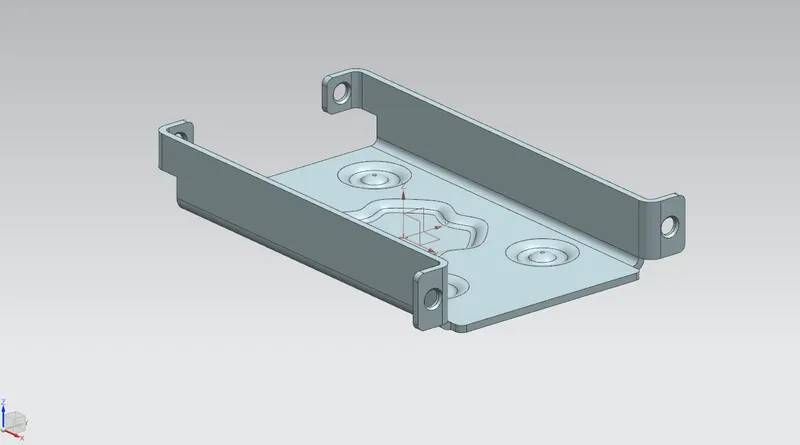
Advanced Sheet Metal Design Using NX Cad Challenge_1_Casing Design
Aim To design a Casing with the help of NX advanced sheet metal.
Introduction:
NX Sheet Metal is a set of tools in the NX design environment that lets you design sheet metal components quickly and easily, depending on the material and production method. Material and process information is included in sheet metal-specific modeling elements such as bends, flanges, tabs, cutouts, beads, dimples, louvres, corner and edge treatments, patterns, and other formable features in NX sheet metal design software.
We can also transform solid models into sheet metal components fast, as well as manufacture sheet metal portions that enclose other components.
Design Methodology
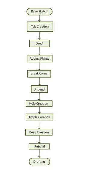
DESCRIPTION:
Sketch:
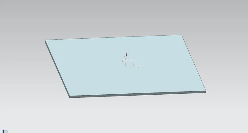
The sketch is the main base for every feature in a sheet metal component's design. A drawing is required for the majority of the features. The initial step is to draw, which will be utilised to make a tab or foundation feature. As a result, the initial sketch might be referred to as a basic sketch. Other tab characteristics' children's features may need a return to a certain plane or face in the drawing.
Tab:
The tab is the very first element in the design of any sheet metal component. The basic feature or tab is the foundation for all other sheet metal features in Siemens NX. After a drawing is made in either of the planes or datum planes, a tab is formed. The tab is always the parent feature for all subsequent features. The tab is constructed in this case design following a basic drawing in the XY plane.
Cutout:
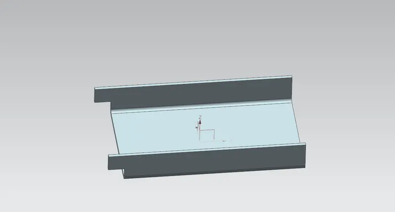
Bend:
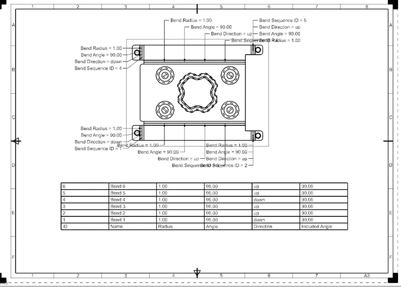
When a bend in a sheet metal component is required, the Bend feature is added. It could be in any angle or position. To make a curve, you'll need a drawing. It could be a straight line or a curve, and it could be an open profile. For this casing design project, the bending curve is depicted as two symmetrical straight lines with regard to the X-axis.
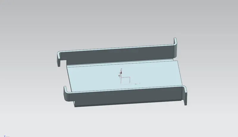
Flanges
The flange is an extra face generated automatically from any existing sheet metal component's edge. It's extra material attached to any face or edge that's bent away from the main edge or face. It can be at any angle or in any position. Four basic flanges are constructed using the material inside the edge of the existing component for this casing design.
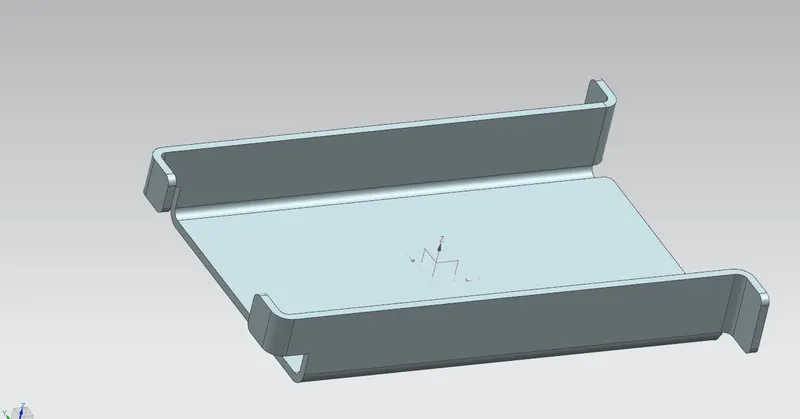
Break Corner:
This feature smoothes out the sharp edges in the corners and adds chamfer. It's similar to the fillet feature in other CAD programmes. It stops the sharp corners from shattering into fractures.
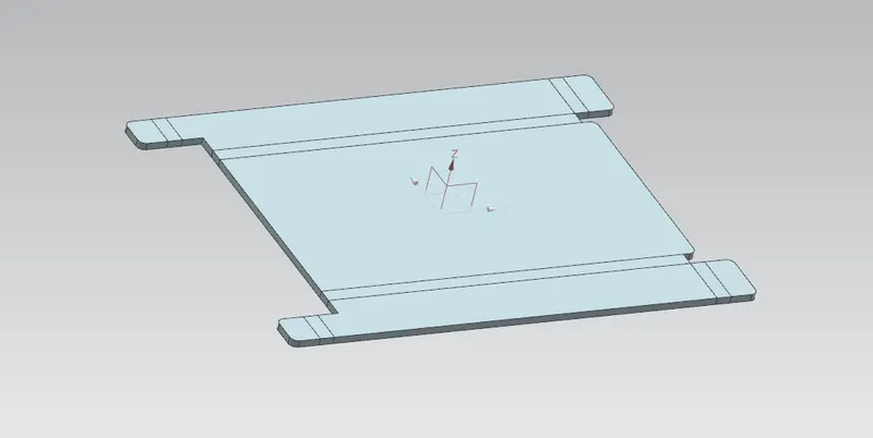
Unbend:
In Siemens NX, this is a very strong and valuable tool. It permits all of the bends caused by the various characteristics to return to their original state at the same time. It is crucial to choose the bends in the correct order in order to obtain a flat sheet metal arrangement as per the design objective. You can also box pick all of the bends at once.
Following the use of the unbend function, further features can be added to the sketches made in the unbent state.
Hole:
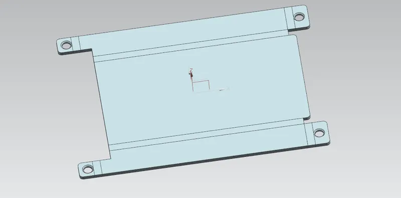
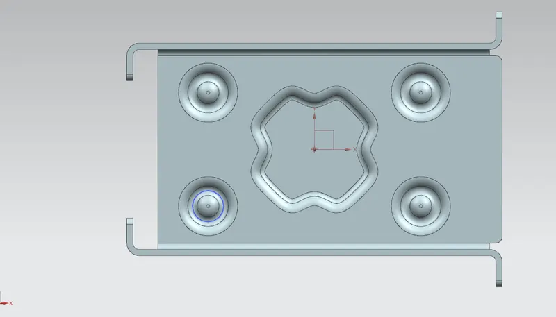
The model workbench has the same hole feature as the sheet metal design workbench. Simple, counterbore, countersink, or tapped holes can all be made using it. First, the four points symmetric to the x-axis in position are sketched, and then the hole feature is applied.
Dimple:
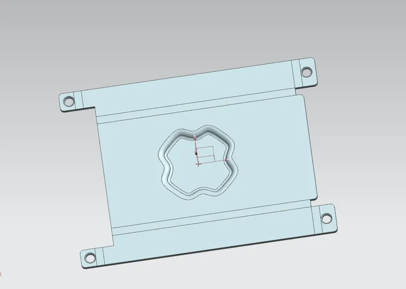
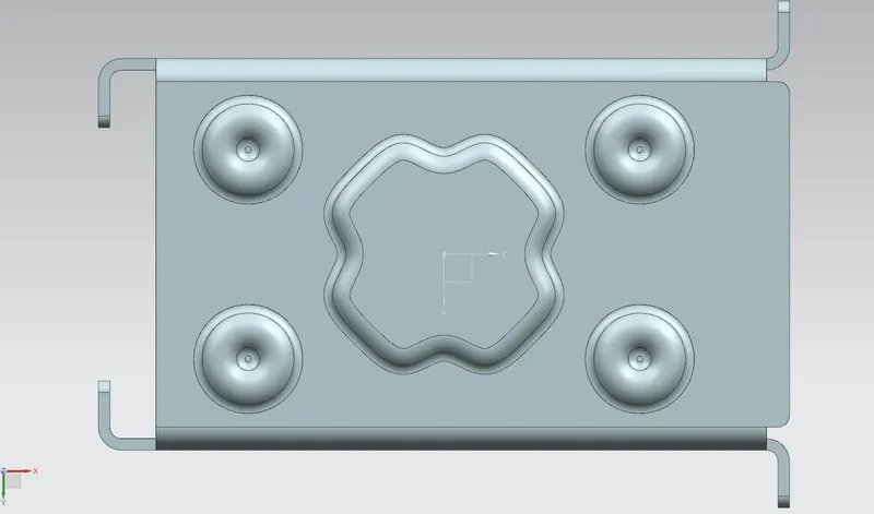
Dimples in sheet metal components provide the component's flat structure extra strength and rigidity. In Siemens NX, the dimple feature is created by sketching any face or flange of a sheet metal component. At the middle of the component, a dimple made up of a 16-point curve is used for this casing design project.
Beads:
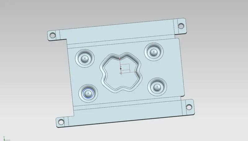
Beads are the features added in sheet metal components in order to increase the stiffness of the component. Beads require a sketch in order to apply the
feature. It can be either an open or closed profile. For this casing design project, four small beads are applied in the symmetric positions as shown in the image
below
Rebend
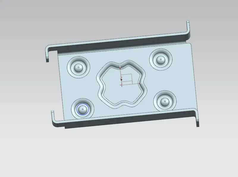
All of the features that are added after the unbend feature are added to the unbend state. The sheet metal component must be rebent to the necessary position after the inclusion of sketches and additional features is done. This is done by selecting all of the bends in order or by box selection utilising the rebend tool.
This completes the casing design process by include the features.
Flat Pattern:
Flat pattern is the representation of the entire sheet metal component in the 2D form of the flat sheet metal with all the bends, cut-outs, holes, and additional
features in the form of lines or edges. The flat pattern ensures the ability to cut the sheet metal out of the raw sheet metal plate. It removes the possible errors
such as interference or collision within the same component
Drawing sheet
TOP VIEW
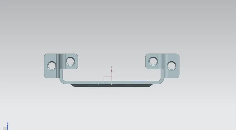
LEFT VIEW
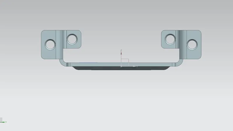
FRONT VIEW
RIGHT VIEW
BOTTOM VIEW
ISOMETRIC VIEW