Week 8 - Challenge 2 - Base Bracket Design
DESING AND DRAFT ANALYSIS OF BASE BRACKET
AIM:-
To make a solid model from the given class a surface an making a draft analysis using CATIA.
INTRODUCTION
CALSS A SURFACE:- A surface created by the designer and handed to the plastic modeller to work on It is the aesthetic surface as well as the outermost surface.
CLASS B SURFACE: A surface with a thickness less than a specific value from the class- A surface is a surface of class B. This is the surface of a model that comprises engineering characteristics.
CLASS C SURFACE:- The Surface joining class A and B surface to form a solid model.
METHODOLOGY:
The concepts used in the model are as follows:
- Tooling axis
- Draft analysis
- Class-B surface
- Class-C surface
- Making a solid model from surface.
CATIA Tools used in this model are:
- Extract
- Un-trim
- Trim
- Extrapolate
- Offset
- Edge fillet
- Boundary
- Sweep
- Join
- Close (part design).
CREATING A TOOLING AXIS.
1. First, confirm that the class-A surface is properly joined and free of discontinuities. We may use the boundary command or the join command to do this.
- Examine the design manually or visually to determine which direction is best for the tooling axis.
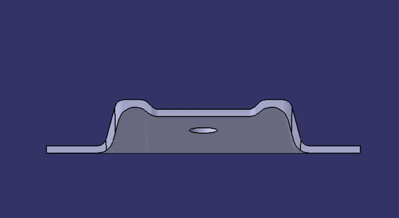
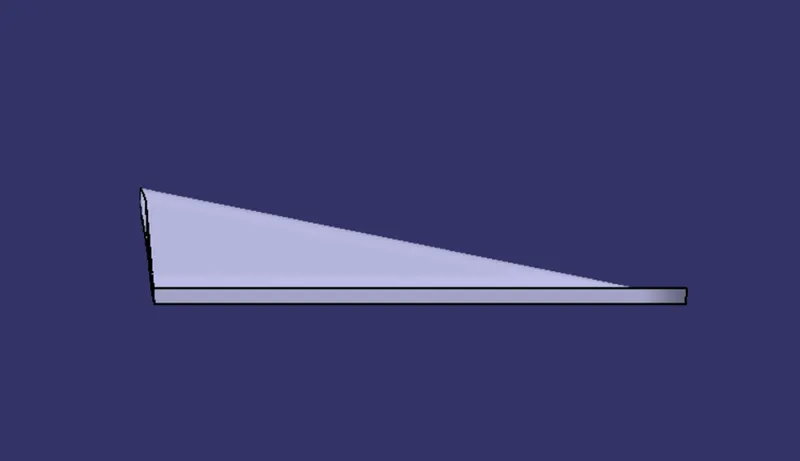
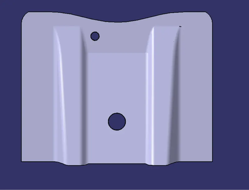
- Since we can observe two holes and a flat surface in 3D perspective, we may take the tooling axis perpendicular to that. But, just to be sure, let us evaluate all of the possibilities. The pictures below of the front side and top views indicate the regions to consider while selecting tooling axes. Because we can't see a hole from X, we can't take an axis along it. We can't find any holes in Y, thus we can't take the tooling axis there either. However, in Z, we can see two holes and a smooth surface, allowing us to determine the tooling axis
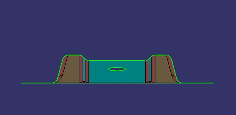
X-direction picture.
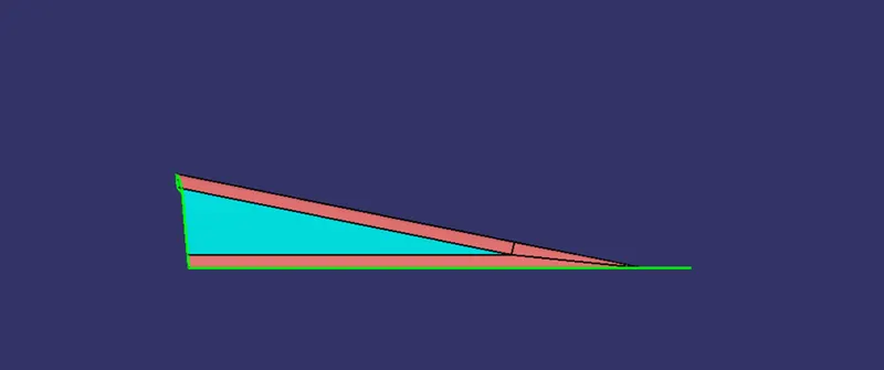
Y direction picture.
.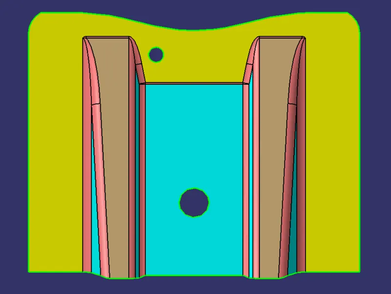
Z-Direction picture.
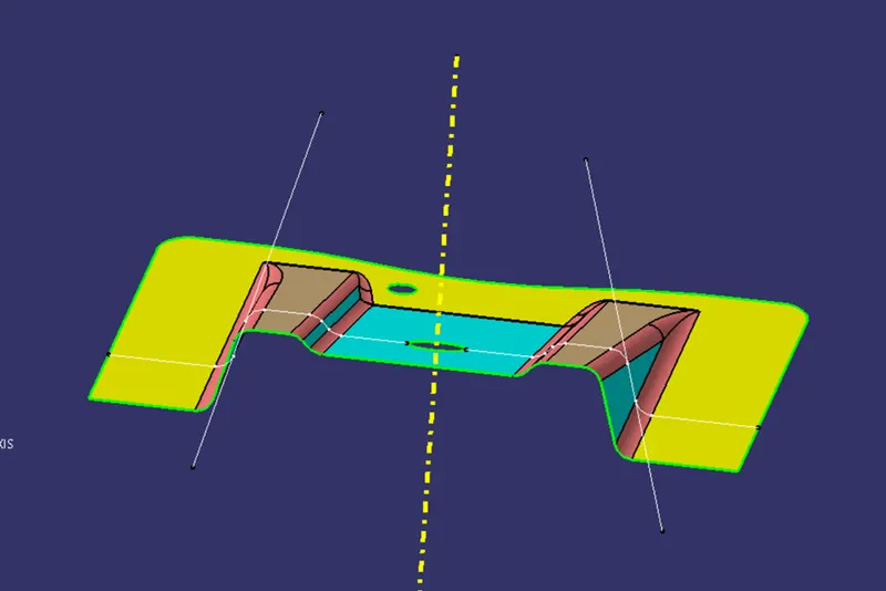
4. To make sure which is the right tooling axis for the component we 1st create a dummy tooling axis.
Create a new axis System by using a center point of the big circle.
5. When the ZX plane of the axis system is intersected with the input, we can observe that there is no surface that might cause an issue during tooling in this direction.
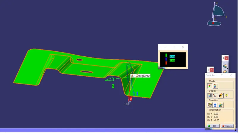
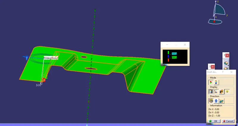
FOR DRAFT ANALYSIS:
- Go to INSERTàANALYSISàFEATURE DRAFT ANALYSIS.
- . Centre the tooling axis on the compass.
- Click on the surface to check whether it is within the drafted values' of permitted limits.
- The total surface should be green, that means the component is having a minimum draft angle and the appropriate value (3 degrees) should be entered in the column.
CREATING CLASS B SURFACE
To make modelling easy we divide the given CLASS A surface and make part my by part.
First, we create outer two RIBs and the middle inclined surface and the outer flat surface.
Class B surface components should be created at a offset distance 2.5mm from class A since Thickness of the component is 2.5mm
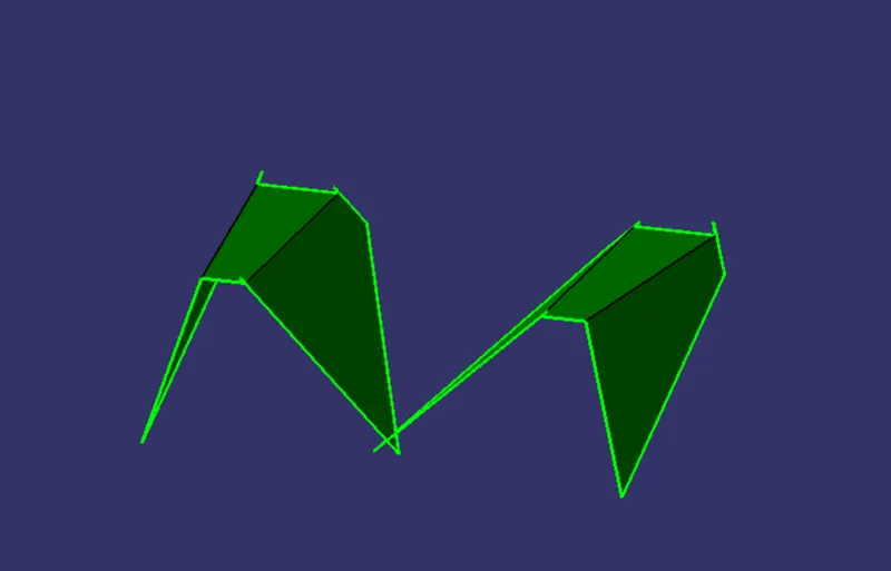
CREATING OF TOW RIBs
Commands used to create Ribs
- Extract the rib surfaces (1 rib at a time).
- Un-trim the surface.
- Extrapolate it.
- Offset it by 2.5mm i.e. thickness.
- Trim to get the desired shape.
- Repeat it with the second rib too
CREATING MIDDLE INCLINED SURFACE:
- Extract the Inclined surface.
- Un-trim the surface.
- Extrapolate it.
4. Offset it by 2.5mm i.e. thickness.
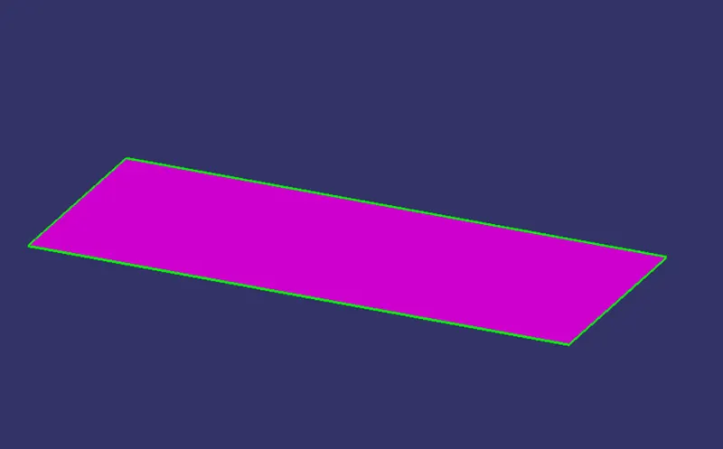
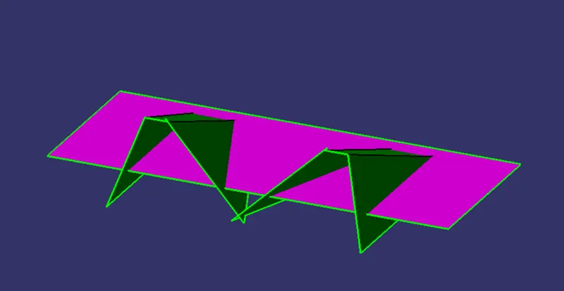
Pink colour surface is the middle inclined surface.
CREATING OUTER SURFACE FLAT SURFACE:
- Extract the flat surface.
- Un-trim the surface.
- Extrapolate it.
- Offset it by 2.5mm i.e. thickness.
After that, we must trim the surface to get the precise form of the class-A surface (without fillet) within 2.5mm. Fillet the model when you've finished cutting it. Filleting formula = fillet value + thickness (if the surface is below). We now have our class-B surface.
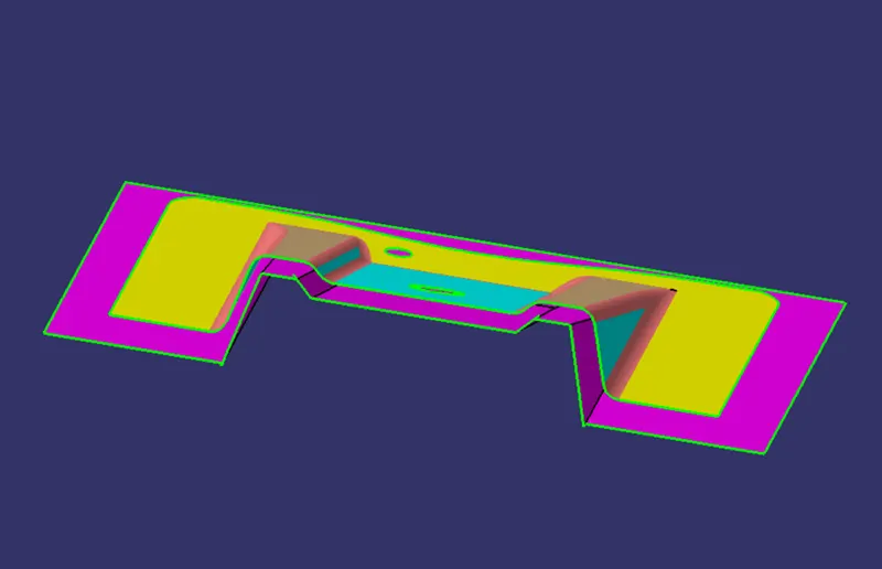
B Surface Without Fillets
Now by using a measuring tool. Measure the radius of the fillets of class A surface
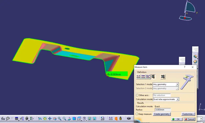
Give 3mm fillet radius to all edges of B surface
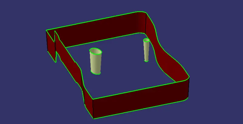
CREATING OF CLASS C SURFACE
- Extract the boundary of the class-A surface.
- Extract the boundary of the holes on the class-A surface.
- Use sweep command on the boundaries one by one to get the class-C surface
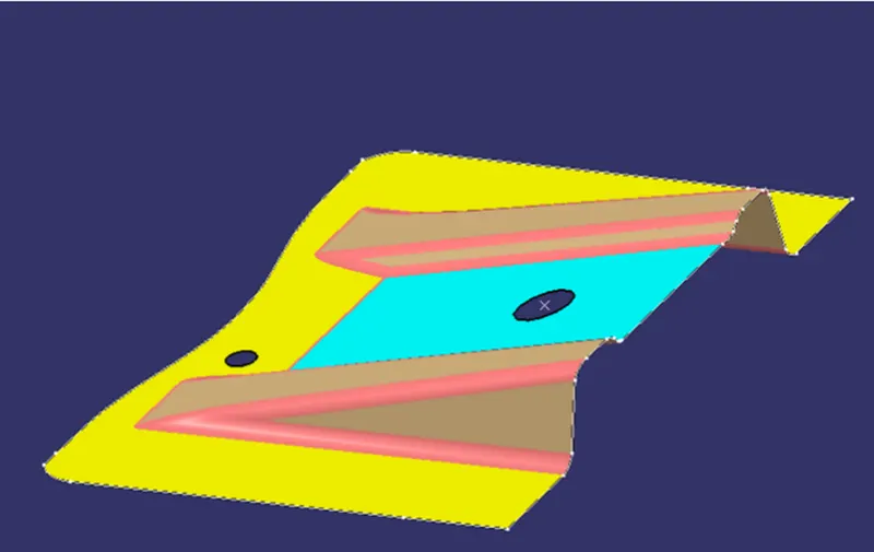
FINAL BASE BRACKET:
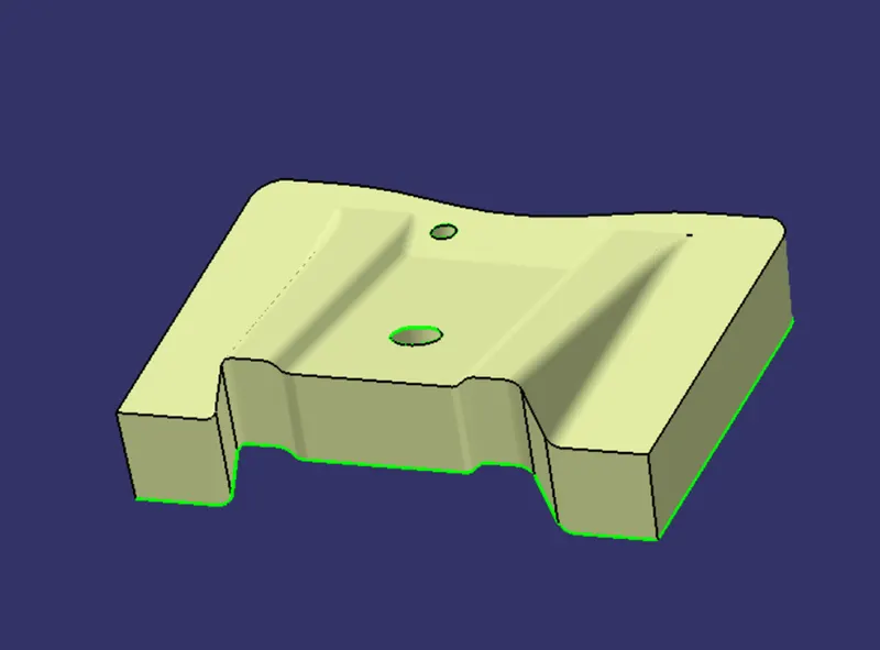
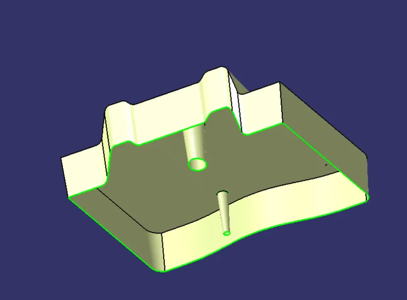
- Join the class-A and class-C surfaces together.
- Trim the class-B surface with the join created earlier.
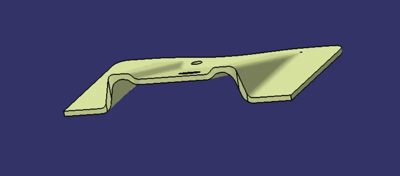
- Go to part design and close the model
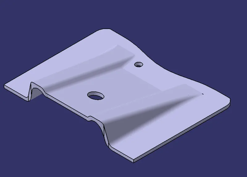
Images of solid model
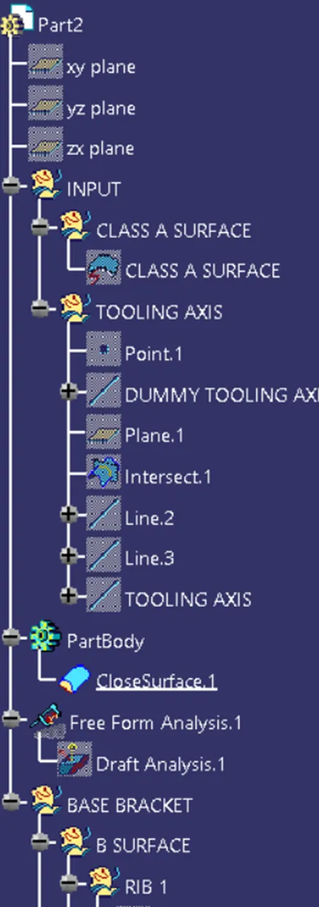
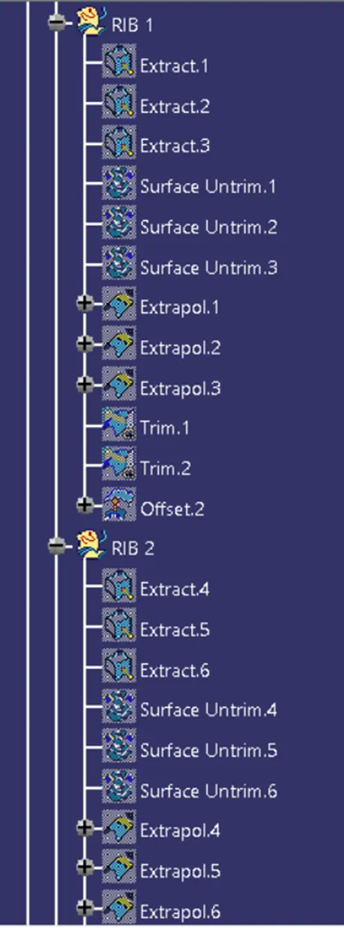
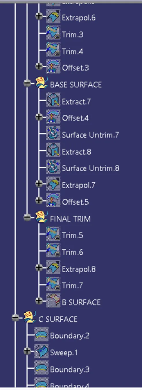
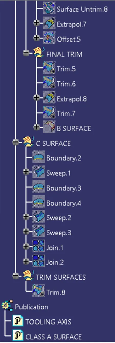
Tree structure
CONCLUSION
Given surface A surface is converted into a solid model with a thickness of 2.5.