Week 8 - Challenge 3 - Switch Bezel Design
DESIGN AND DRAFT ANALYSIS OF SWITCH BEZEL
AIM
The aim is to design a switch bezel and conduct a draft analysis for it using . The Bisecting approach to create the needed tooling direction.
INTRODUCTION
CLASS-A SURFACE: a surface made by the designer which is given as an input to the plastic modeler to work on. It is aesthetic surface and the outer most
surface.
CLASS-B SURFACE: a surface below a certain thickness from the class-A surface is class-B surface. This is the surface that contains engineering aspects of a
model.
CLASS-C SURFACE: a surface that joins class-A and class-B surfaces is class-C surface.
METHODOLOGY:
The concepts used in the model are as follows:
- Tooling axis
- Draft analysis
- Class-B surface
- Class-C surface
- Making a solid model from surface.
CATIA Tools used in this model are:
- Extract
- Un-trim
- Trim
- Extrapolate
- Offset
- Edge fillet
- Boundary
- Sweep
- Join
- Close (part design).
PROCEDURE FOR CREATING THE SWITCH BEZEL
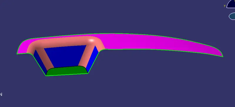
- The given style surface is first checked for imperfections, and if any are discovered, they are repaired using the Trim, Extrapolate, Split, and Join commands.
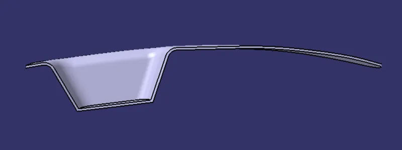
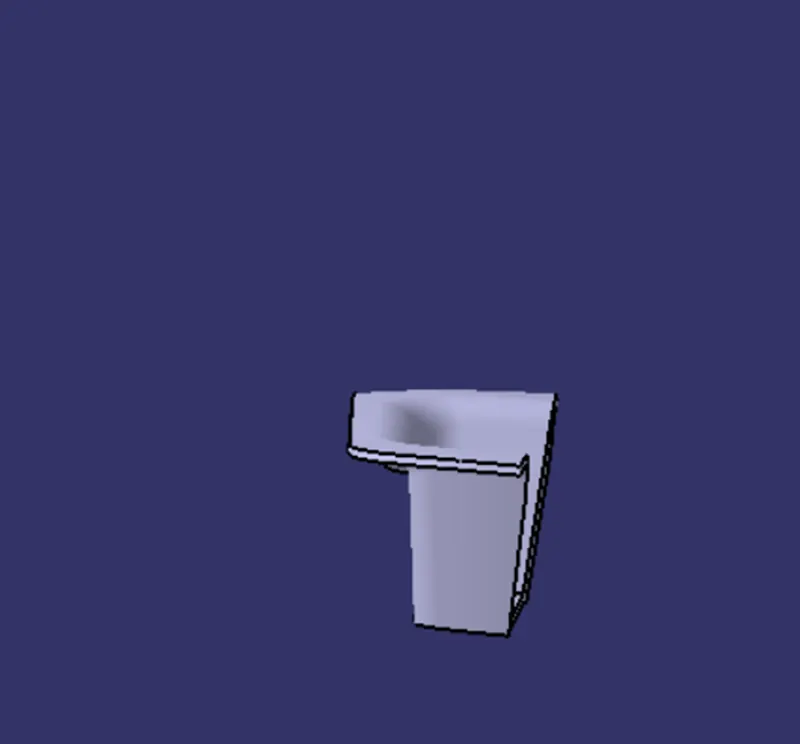
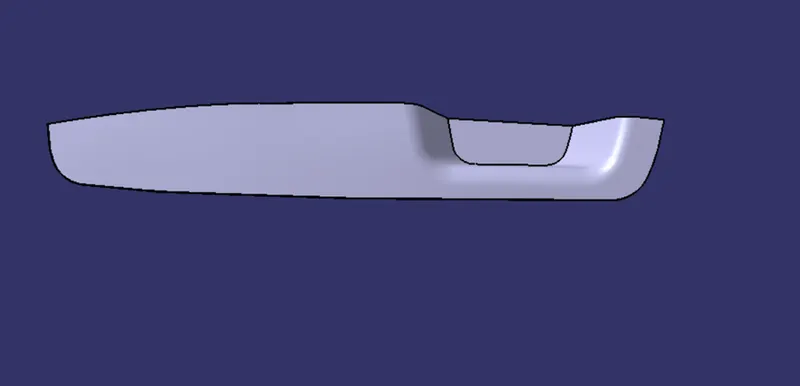
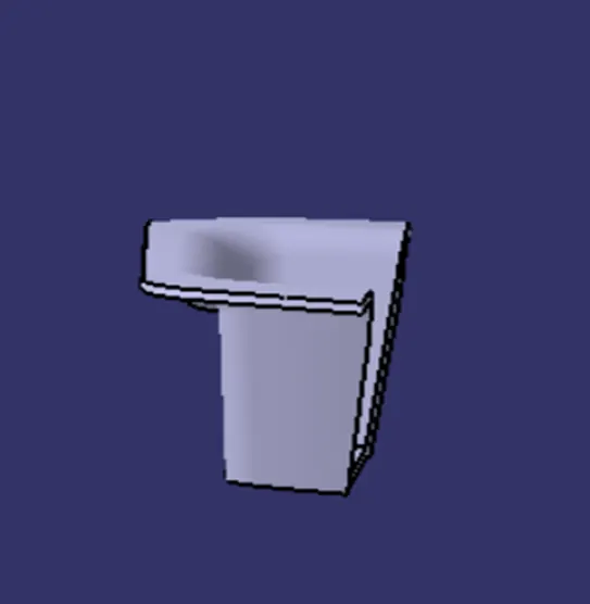
- Let's go on to the following phase now that the Class – A surface is clean and free of imperfections, as seen in the figure below.
CREATING A TOOLING AXIS.
- The interior trim (switch bezel) must have a nominal 3-degree draft angle when ejected from the cavity of the mould after production.
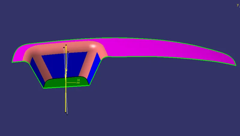
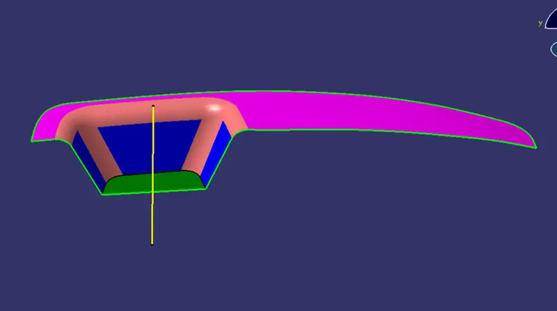
- Hence the tooling direction is created by considering the above factor and bisecting method is used..
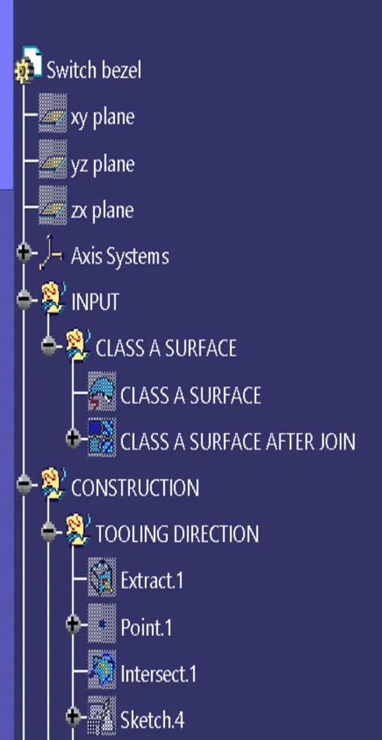
- The class – A's bottom surface was taken, a point in the center was generated, and an axis system was introduced with the current feature deactivated.
- The two inclined lines were then drawn inside the positioned sketch using project intersection along the yz plane.
- Then bisecting lines with the two inclined lines were drawn
- Now repeat the technique throughout the xz plane, but because one side lacks inclined lines, the centre point is used to extrude a line along the z direction, yielding a 5 degree measurement (Tentatively).
- The bisecting line is created and published using these two lines from drawings 1 and 2. (tooling direction)
CREATION OF CLASS – B SURFACE
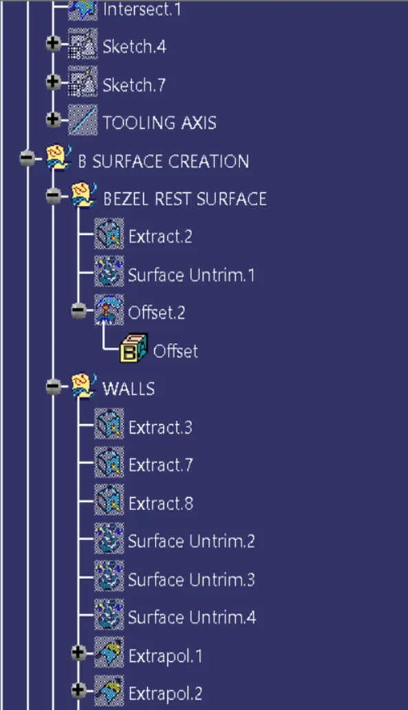
- The necessary surface, excluding the offset surface, was extracted and then all of the surface was untrimmed to create the class-B surface.
- The intersections between all of the surfaces were then extrapolated.
- The B-Surface was offset to 2.5 mm due to the thickness of the Switch bezel, and the necessary trim procedures must be performed.
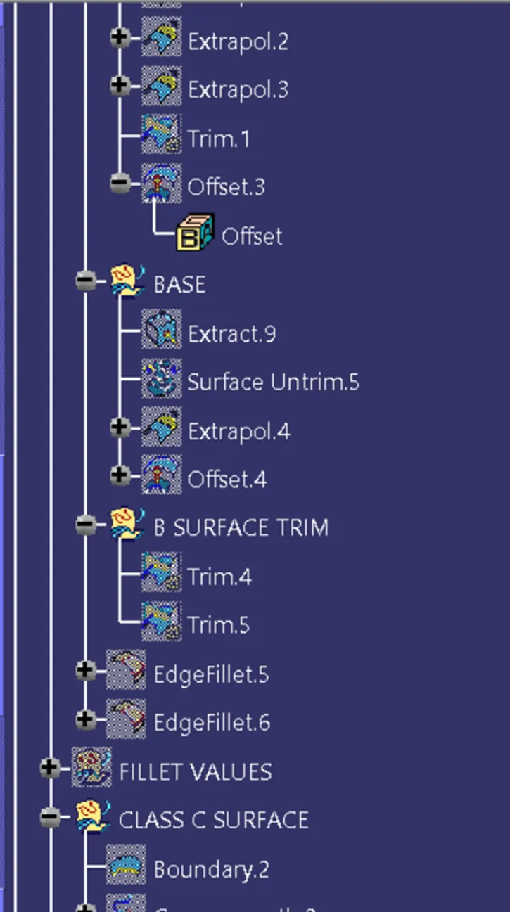
Lastly, the appropriate edges were filled to a depth of 12.5mm (15mm-2.5mm). [Fillet values of the A-surface: 15mm, part thickness: 2.5mm].
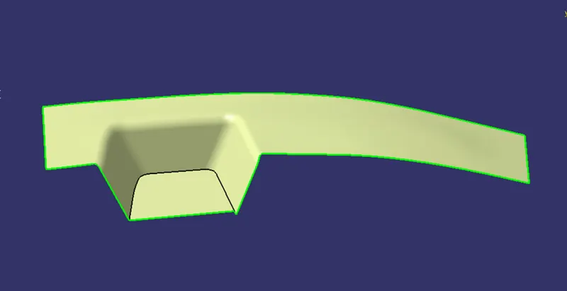 CREATION OF CLASS – C SURFACE
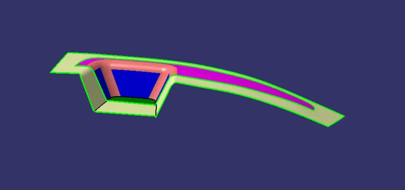
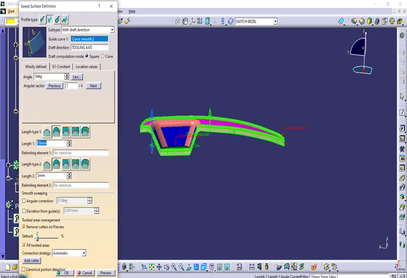
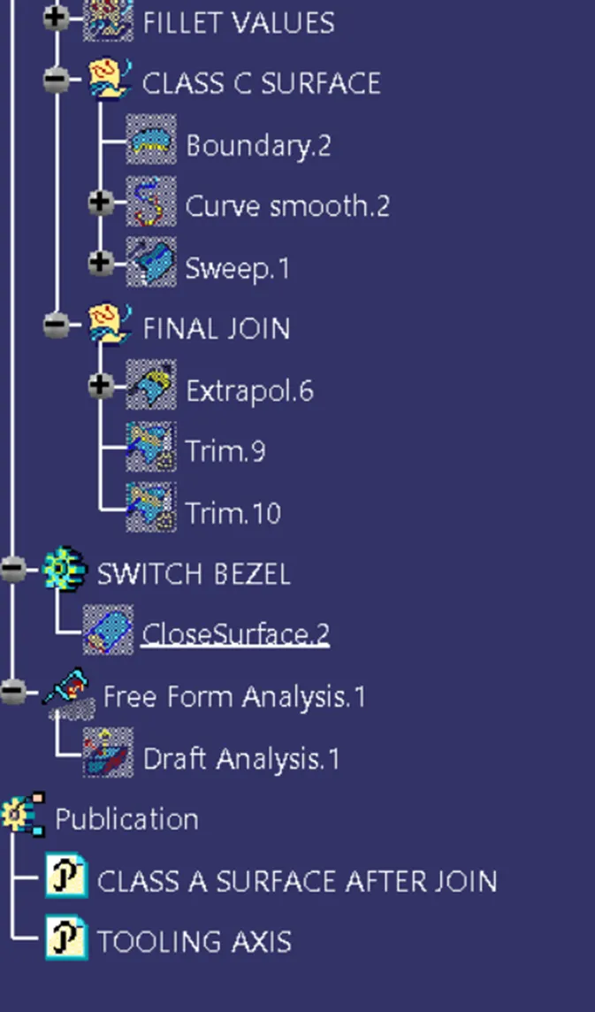
- Multiple Extract was used to extract the A- Surface outer margins. The curve is then smoothed with the Curve Smooth option to avoid the spots.
- The surface was therefore generated with the following feature parameters using the sweep command:
- Profile type – Line
- Subtype – With Draft Direction
- Guide Curve – Smooth Curve
- Draft Direction – Tooling Axis
- Draft Computation Mode – Square
- Angle – 3 Degree
- Angle Sector – Positive Downward (1)
- Length – 20mm
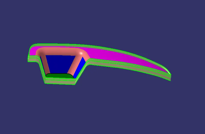
- The margins were then intersected between the surface corners using the extrapolation command, making trimming easier.
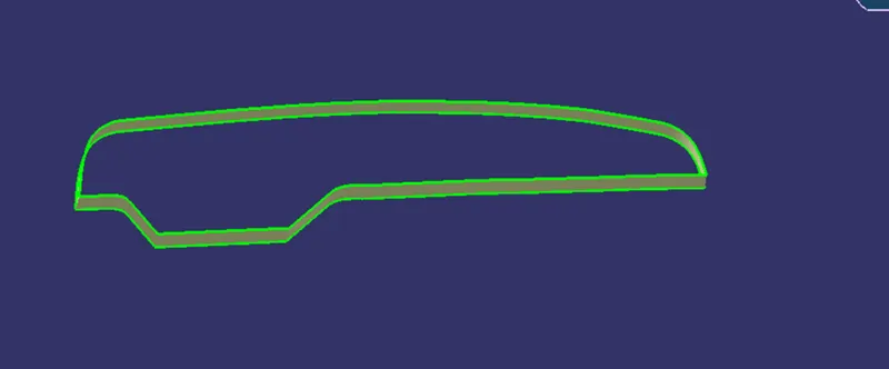
- The necessary section of the C – surface was now trimmed away.
CREATION OF CLOSED SURFACE
- Extrapolation (tangent continuity) and Trim surface were used to link the Class A and Class C surfaces together by reducing the gaps between them.
- The specific surface of the Switch bezel was therefore trimmed with the class-B surface from the above-resulted trim surface.
- The component's solid body is then produced by utilizing the Closed Surface command in Part Design to define the part body.
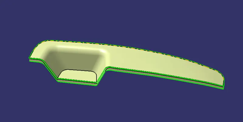
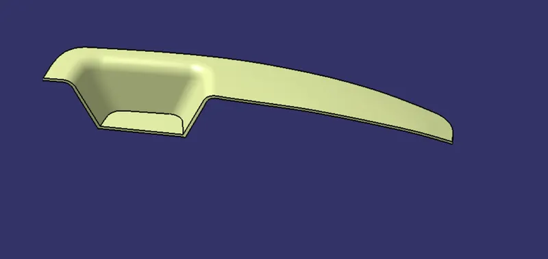
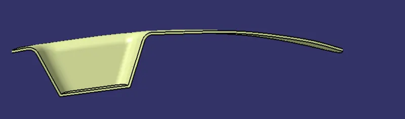
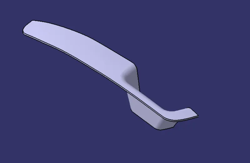
PROCEDURE FOR DRAFT ANALYSIS
- Before generating the Class –B&C surface, the Class –A surface must be checked, and then the solid body must be examined. Both can be accomplished by following the steps outlined below.
- The feature draft analysis is enabled by switching the view mode to custom view parameters – Material mode.
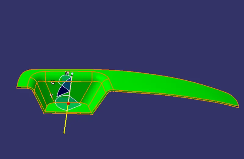
- The compass was then activated and aligned with the tooling axis by sliding the red pointer and locking it in position.
- The nominal value will be 3 degrees, and the component's draft angle will be evaluated by selecting the rapid analysis mode.
- The green color area indicates that it meets the 3-degree draft angle requirement. If not satisfied, the area is measured and then adjusted using the Running point tool to produce a successful draft for the created tooling direction.
CONCLUSION
Finally, the Tooling Direction for the Class – A, B, and C surfaces has been published, and the Switch Bezel has moved on to the next operation – the construction of B-side features.