Week 8 - Challenge 5 - Core & Cavity Design
Core and Cavity Design for Switch Bezel
Core and Cavity Design for Switch Bezel - Plastic Component Mould.
This study illustrates the design of Core and Cavity Blocks for an Automotive Plastic Component – Door Switch Bezel using manufacturing fundamentals such as Parting Surface and Parting Line definition, Draft angles, Draft Analysis, defining and implementing Tooling Axis, Class A, Class B, and Class C surfaces, and keeping the part thickness at 2.5mm. Surface Design and Solid Design approaches are used in the CAD program CATIA V5 to design the moulds.
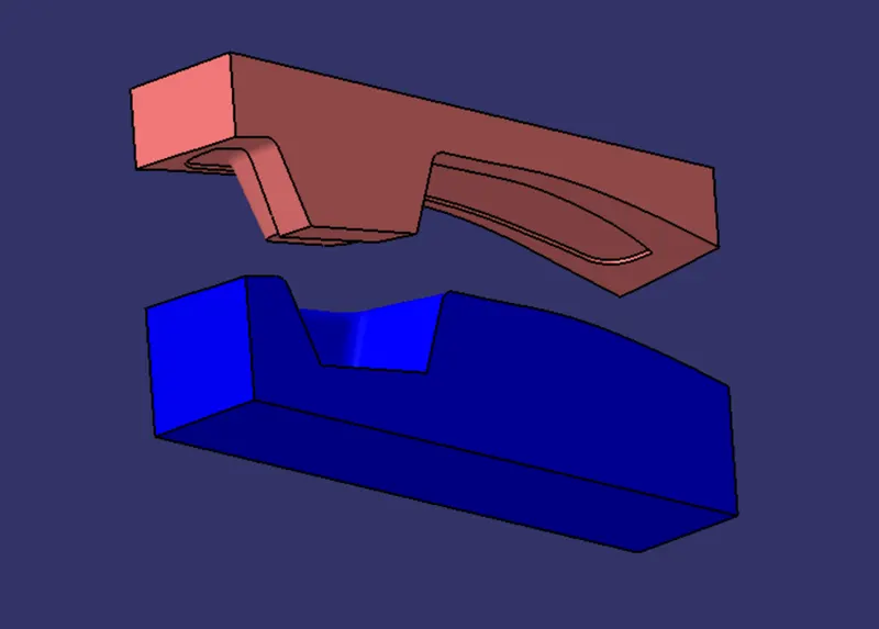
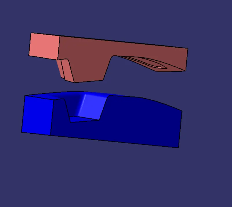
Core and cavity of a switch Bezel.
The concepts are explained shortly below.
Parting Surface:-
- Injection molding is made up of two basic parts: the movable half and the fixed half.
- During the injection molding process, these two parts are forcefully pushed together to produce a sealed hollow, preventing melt flow leakage and maintaining a particular holding pressure.
- The pressed surface is referred to as the Parting Surface.
- The separating surface is often the largest projection outline of the component.
- Parting Surface has a direct impact on product quality, ease of construction, and operation of the mold injection, and mold design is one of the most important variables in success.
Design of Parting Surface should follow the following Design Principles:
- Making as little changes as feasible to the mold structures.
- To reduce mold complexity, avoid or minimize side splitting as much as feasible.
- De-Molding Ease. In most circumstances, the plastic component must remain at the fixed half and be ejected by the Ejection System to avoid side DE molding action.
- To decrease manufacturing and assembly mistakes, ensure the dimensional correctness of the molded components and aim to produce pieces with comparable dimensional accuracy requirements in the same module.
- Ensure that the molded pieces meet the Appearance Requirement.
- Because flash or mismatch is common on the Parting Surface, it should not be constructed on a High quality requirement Surface.
- Make sure there is enough venting or De-gassing. Parting Surface should be put near the conclusion of the Mold Flow if at all possible. This can be advantageous for filling and venting.
Parting Line
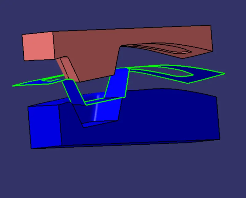
- The intersection of the Plastic Component and the Parting Surface is referred to as the Parting Line.
- It is the Component's Bordered Outline on the Parting Surface.
- Figure shows the Switch Bezel Parting Line.
Draft
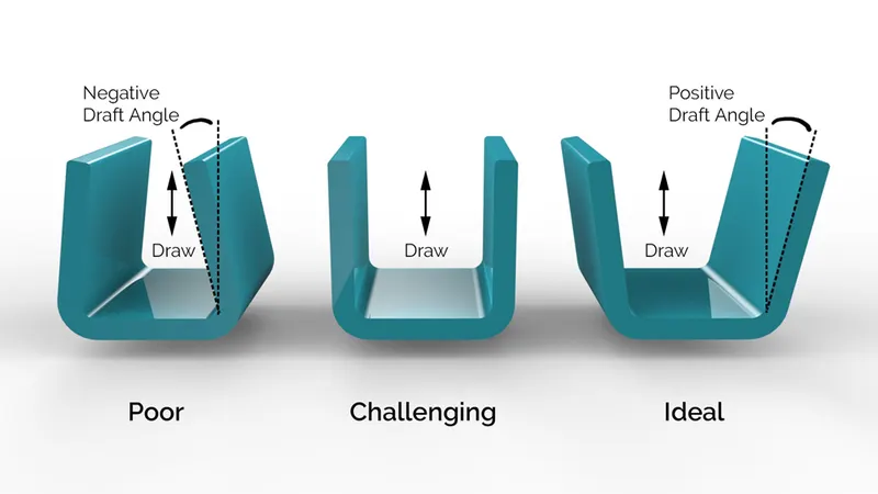
- Every Plastic Component that must be made is given an angular tapering at the design stage.
- It is offered in the Mold Movement direction.
- The Draft helps the components to freely release from the mold without causing friction between the component's surface and the core and cavity plates.
- When a plastic component cools inside the mold, it naturally shrinks and attaches to the core or cavity half.
- The movement of the mold opening generates friction on the component's walls as well as the core/cavity blocks.
- This shortens the life of both the mold and the component..
- As a result, the component may have a rough surface finish and a fragile structure.
- This issue may be resolved by providing a draft to the component.
- Most applications demand minimum draft angles ranging from 0.5 degree to 1 degree, however 3o draft angles are often approved for cost-cutting purposes.
- Textured surfaces, such as instrument panels, are given draft angles of 7 degree.
- Screw bosses, ribs, and stiffeners are provided the smallest draft angles feasible because to their crucial importance.
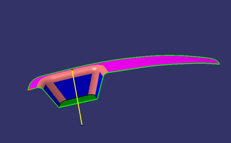
Tooling Axis: -
- The direction in which the Mold opens and closes is referred to as the Tooling Axis. Along this axis, part drafts are provided.
Draft Analysis:
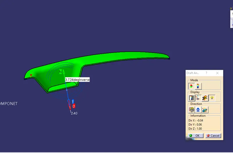
- Draft Analysis is a CATIA tool that uses color codes to identify zones that vary from the prescribed values of angles along a chosen draft direction.
- It uses colors to highlight the draft zones.
- The initial stage after getting the component's Class A is draft analysis.
- To make the plastic component manufacturable, a draft analysis must be completed.
- Draft angles that are acceptable are utilized as a range for draft analysis.
Class- A Surface
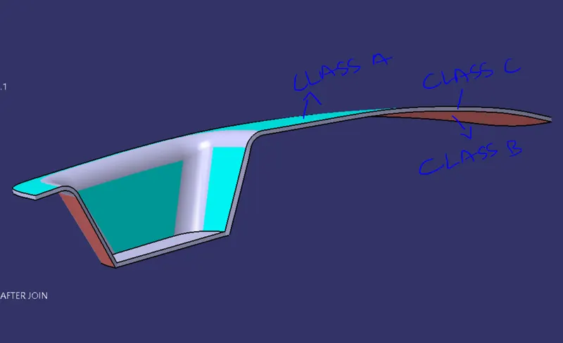
- A class A surface in automobile design is any of a group of freeform surfaces with exceptional efficiency and quality.
- It is any automobile component's apparent cosmetic surface.
- Class A surface is any visible surface in a product that adheres to the physical meaning.
- This categorization is largely utilized in the automobile business, but it is also increasingly employed in the consumer products market.
- It is a need in which aesthetics plays a vital role.
- As a result, the outside of vehicles is classified as Class-A.
Class- B Surface:
- Class B surfaces are Engineering Surfaces that are either invisible to the naked eye or are located on the back side of Class A surfaces.
- It is mostly the component's thickness or Class A.
- These surfaces must be constructed in accordance with the Class A surface, i.e., the continuity, thickness of the component, functionality, and so on.
- Screw bosses, ribs, snaps, stiffeners, and fixations are among the key engineering elements found on these surfaces.
- Because B surfaces are not visible to the naked eye, they do not include any visual style elements or textures.
Class- C Surface:
- Class C surfaces link Class A and Class B surfaces.
- Along the Tooling Axis, this surface joins the A and B surfaces.
- It includes the draft created in accordance with the design.
- It is the thicker surface between the A and B surfaces.
- Figure below depicts surfaces of classes A,B, and C
MOLD DESIGN FOR THE SWITHC BEZEL
Creating Parting Surface
- To extract the border of the Class A Surface, use the Boundary Operation, as illustrated in Figure below.
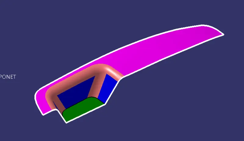
- Extrapolate the boundary with the necessary value and trim it with the Class C surface, as shown in blue in the figure below.
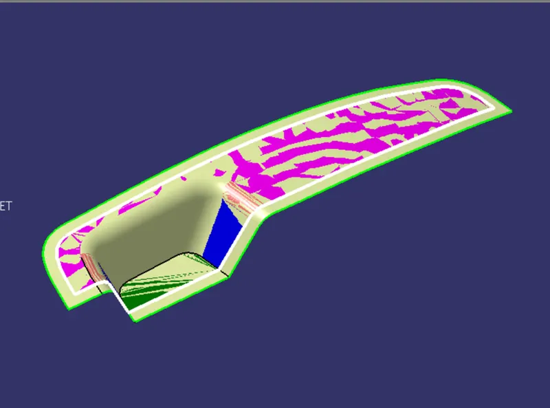
- Trim this with the B Surface to achieve the result shown in the figure below.
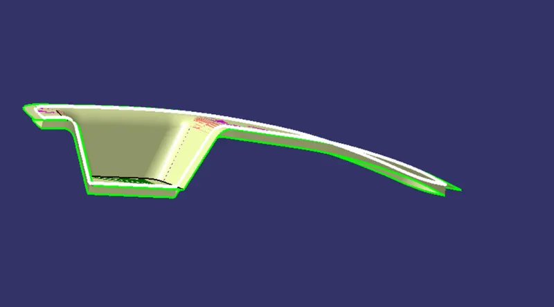
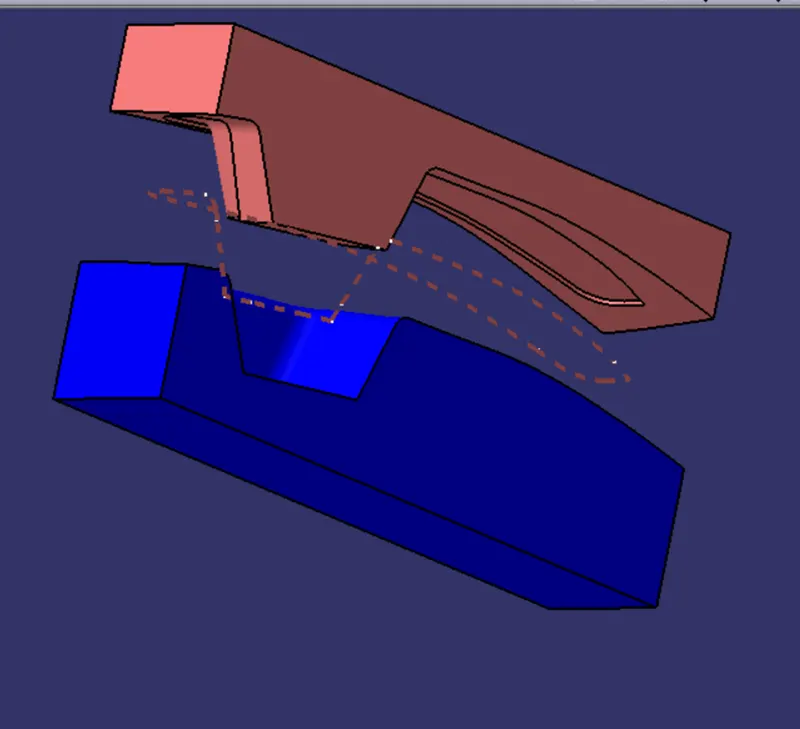
- This is the needed Parting Surface, which is seen below.
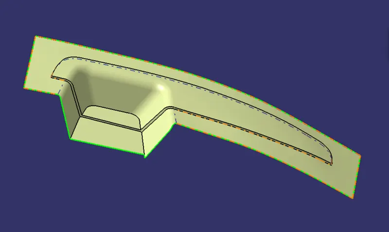
Creating of Core And Cavity Blocks:
- Make a rectangle drawing on the Plane that is normal to the Parting Surface and extrude it to make the Core surface.
- It is depicted in the figure below.
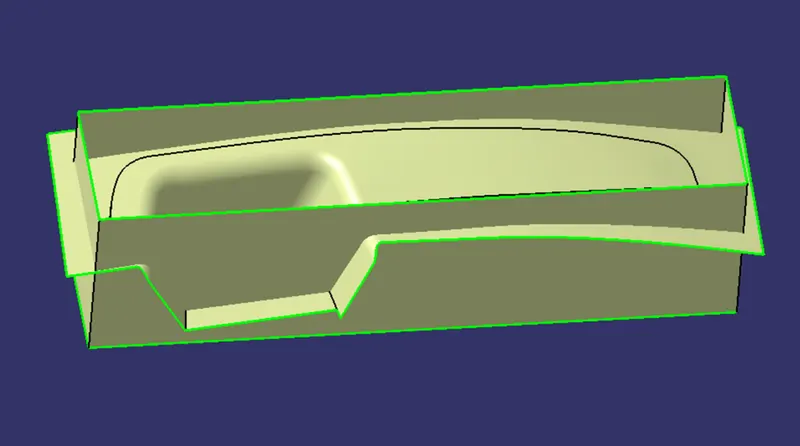
- Extract the Core Block's outside top border and Fill the top to produce a closed Surface.
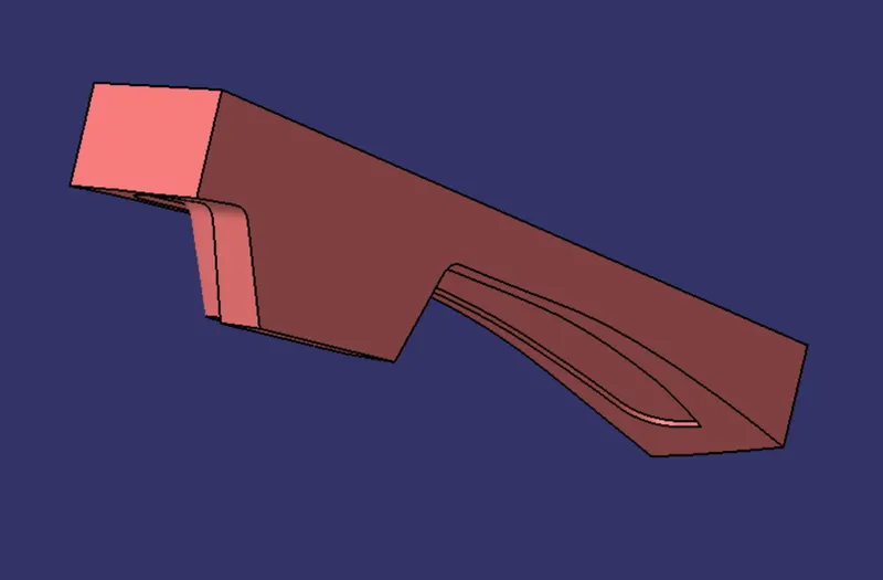
- Connect the Fill surface and the Core Extrude
- Trim it using the Parting Surface to get the Core Block eclosed Surface illustrated in Figure.
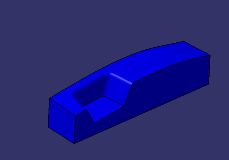
- Extrude the same drawing on the opposite side to make a Cavity Block, then Fill and Join the Surfcace as illustrated in Figure.
- Change to the Part Workbench and transform the Surfaces to solid parts.
- Closed Surface is used to make a Solid Part for the Core and Cavity Blocks.
- Figure below depicts the Core Part and Cavity Block as Solids, with the light brown representing the Core Part and the dark brown representing the Cavity Block.
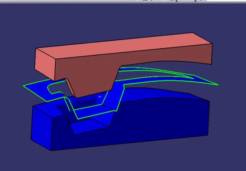
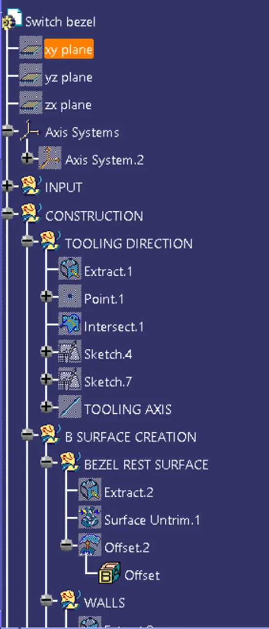
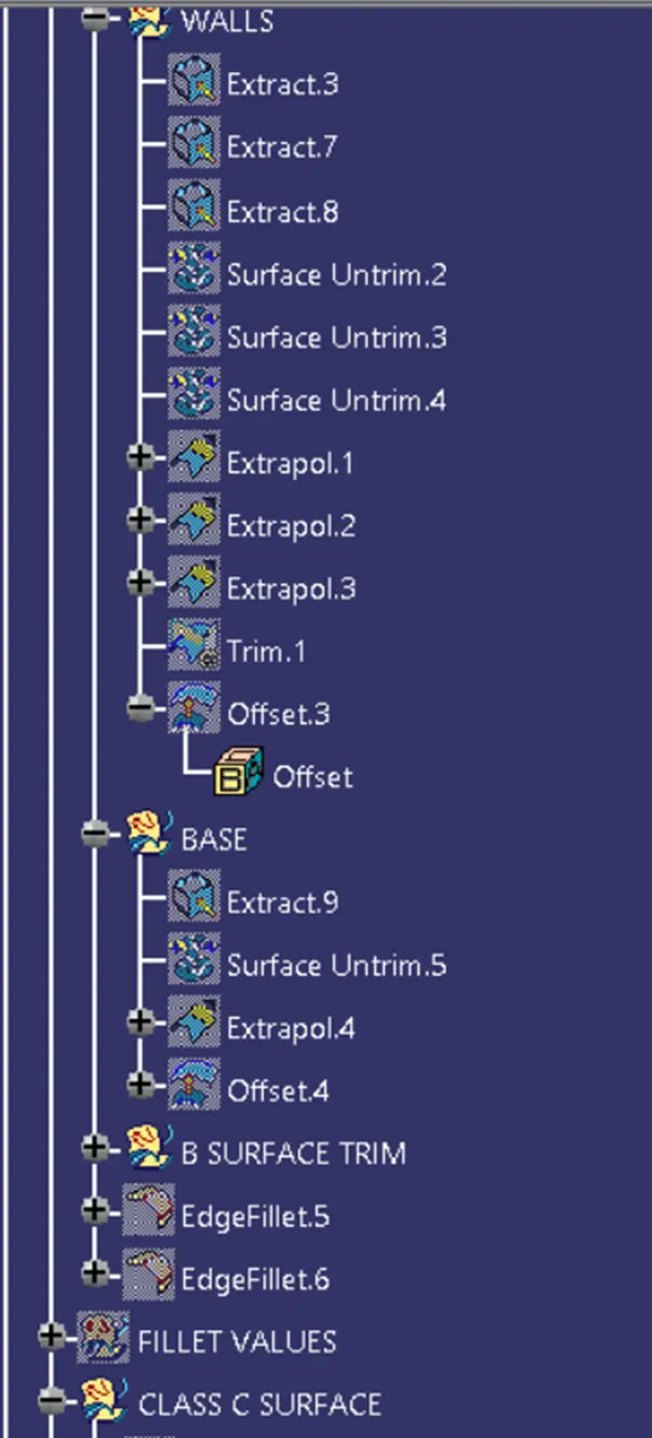
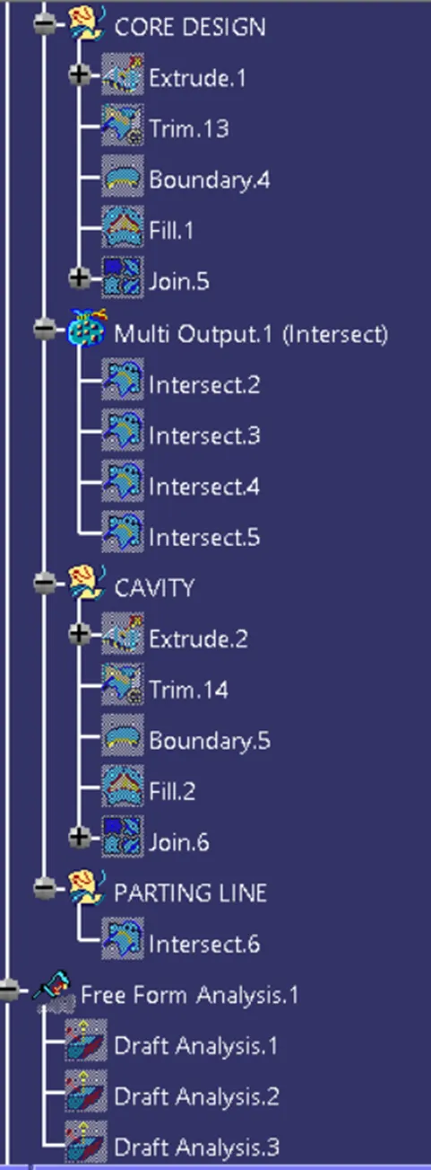
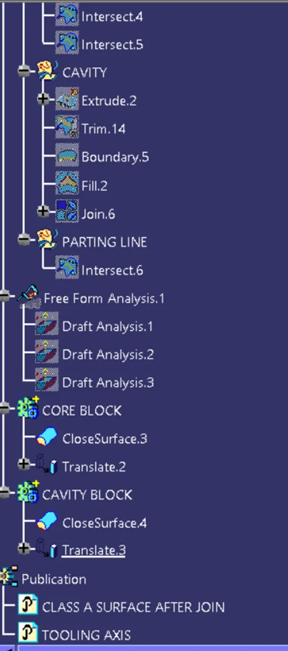
Tree structure
Conclusion
The design of the core and cavity for the mold of an automotive plastic component – door switch bezel – is completed using the concepts of Parting Surface, Parting Line, Draft Angle, Draft Analysis for Class A and Final Enclosed Surface, Tooling Axis creation and implementation, Class B and Class C creation and conversion to a solid part with a part thickness of 2.5mm.