DESIGN AND DEVELOPMENT OF STEPS CLIMBING E SCOOTER
DESIGN AND DEVELOPMENT OF STEPS CLIMBING E SCOOTER
Skill Lync Project By Kranthi Kumar Uppu
|
Contents
DESIGN AND DEVELOPMENT OF STEPS CLIMBING E SCOOTER.. 1
2.2 Battery management systems. 7
3.TYPES OF MOTORS USED IN ELECTRIC VEHICLES. 9
3.2 Permanent magnet brushless DC motor (PM-BLDC) 10
3.5 Switched Reluctance Motor (SRM) 13
6.SELECTION OF HYDRAULIC CYLINDER AND CALCULATION.. 21
6.1 Single - Acting Hydraulic Cylinder: 22
6.1. CYLINDER CALCULATIONS. 24
7.DESIGN AND DEVELOPMENT OF STEP CLIMBING.. 27
ABSTRACT
This project aims to create a battery-powered wheel kart with a stair-climbing mechanism. Wheel kart that can be used by disabled or normal people. A design for a stair-climbing wheelchair that can move in both organized and unstructured spaces, climb over obstacles, and go up and down stairs. The preliminary development is stair climbing mechanism of an in-wheel motor, which features a direct-driven outer rotor type coupled to the E-rear scooter's tyre without any gear, is introduced first The ideal design of this in-wheel motor aims to increase output. properties of the motor, as well as having a stator form to ease automatic winding surface of response The methodology was employed for the CAD Design. The motor may meet the specified speed, power, efficiency, and cogging torque parameters.
1. INTRODUCTION
An E wheelchair is a construction that consists of a set of wheels attached to a chair. A wheelchair is a gadget that can empower and enable a disabled person to live a normal and independent life. One of the contributions for such physically handicapped people is the invention of the wheelchair. folks. It is a blessing for them. Since the invention of the wheelchair, it has been continuously improved. improving in order to increase its comfort level and to include as many features as possible We've encountered a wide range of them. wheelchairs of various shapes, sizes, mechanisms, sources, materials, and so on Many people believe that A wheelchair that is appropriate, well-designed, and well-fitted can be the first step toward inclusion. societal participation. Which can be used by every person.
Environmental issues created by gasoline cars and fuel economy have become increasingly important in recent years. Vehicles of new energy that are green, ecologically friendly, and inexpensive are an important aim for many countries' economic and social development, as well as the vehicle's future development path. Electric vehicles with zero environmental emissions, mileage and fuel consumption can be mutually equivalent.
The electric system plays a promising role in the design and manufacturing of an e-scooter. The electric system is made up of a battery, a motor, a motor controller, and other electrical components. The most significant function of the electric system is to provide power to the motor, which aids in the operation of the scooter. This energy, in the form of chemical or electric energy, is stored in a battery, which is then used by a hub motor, converting the electric or chemical energy to mechanical energy. In the event of a collision, a proper electric system is critical to protect the safety of both the driver and the vehicle. The brushless DC (BLDC) motor is attached to the hub of the scooter’s rear wheel. The compactness and noiseless functioning of BLDC motors are the reasons for their selection.
So our main Objectives to design or development an e-scooter are as follows-
- To reduce running cost of vehicle
- To reduce the emissions
- To increase the life period and efficiency of existing e-scooters
- To help disable people to take steps with the climbing mechanism
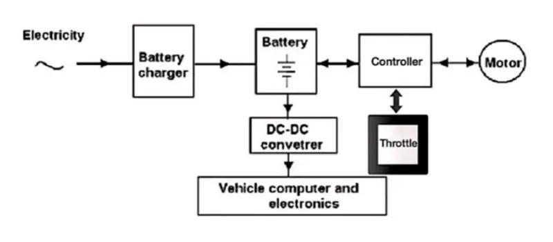
The key components of Electric Vehicle (Powertrain)
2. SYSTEM DEVLOPMENT
The Key Components in Electric Scooter with stair climbing
Following are the key components in Electric Scooter:-
- Seat
- Wheels
- Fender
- Lifting cylinder
- Stair climbing motor
- Battery
- Motor Controller
- Motor
- Climbing belt
- Vehicle Computer and Electronics
The electric vehicle is rather simple in structure. The key components are the propulsion parts. Fig.1 shows the configuration.
The main source of energy storage is the battery. The battery charger converts power from the mains to charge the battery. To drive the motor, the battery voltage is DC, and the current (I) is inverted into a switched-mode signal by a power electronic controller.
2.1 BATTERY
Batteries are the components that store electrical energy, allowing the vehicle's motor to work. As seen in the table, there is already a comparison of various types of batteries. 1 down below, The major materials that allow recharging are nickel-cadmium nickel-zinc, nickel-metal hydride, and lithium-ion/lithium-polymer, which are denoted on the battery analysis table as NiCd, NiZn, NiMH, and Li-ion/Li-Po. Specific energy is energy per unit of mass, and a higher value suggests a lighter battery if the energy is held constant.
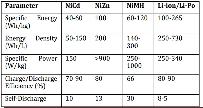
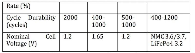
According to this data, lithium-ion batteries are the most efficient choice for an electric bike since they provide high energy density while staying relatively light-weight and small in size. Lithium-ion batteries can be extremely harmful; thus, it is critical to investigate the quality of the lithium-ion cells as well as the safety measures implemented.
2.2 Battery management systems
It is also known as BMS. A battery system is made up of a number of battery cells. They are connected in parallel or series, depending on the design. Each cell should be monitored and controlled. Voltage, current, and temperature are all monitored as part of the conditioning process. The measured parameters serve as decision parameters for system control and protection.
2.3. Electronic Propulsion
The term "electronic propulsion" refers to the process of transferring one type of energy to another as needed.
It is divided into two parts: electrical and mechanical. All electrical components are included in the electrical Motors, power converters, and electronic controllers are examples of electronic components, whereas mechanical components are examples of mechanical components.bwheels as well as transmission device The two sections are separated by an air gap, via which the electrochemical reactions take place. There is an energy conversion. an electric propulsion functional block diagram. power and signal flow representation system
The thick arrow-headed line depicts the power flow, whereas the thin line depicts the signal flow. The power flow can be reversed, and single or many motors can be employed. The diagrams below depict the single and dual motor configurations. Torque, speed, voltage, temperature, flow, currents, and speed are all converted into electrical quantities by the sensors employed in an electronic propulsion system.
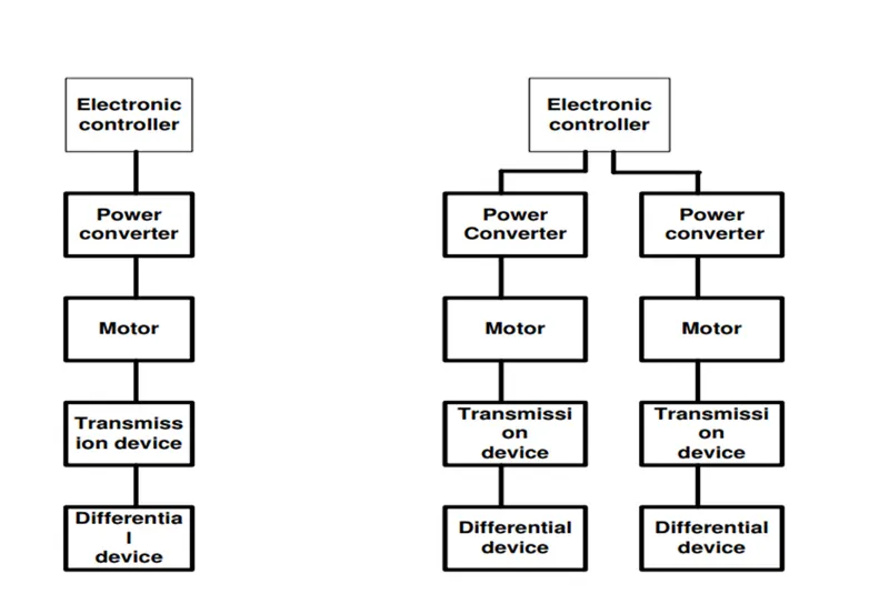
Single motor and dual-motor configuration
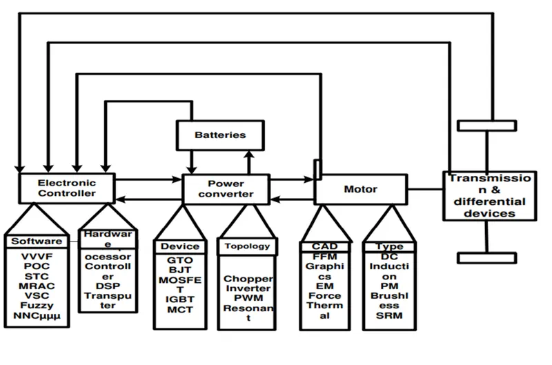
Functional block diagram of EV Propulsion System
3.TYPES OF MOTORS USED IN ELECTRIC VEHICLES
PM brushless motors are the most common form of motor drive utilised in EVs. Induction motors have a lower efficiency than permanent magnet motors. The performance of a PM motor is determined by the type of raw material used in its construction. Because electric motors provide greater freedom in vehicle design, a greater number of motor topologies can be used for improved performance and efficiency. The electric motor should have a strong torque in locations where the vehicle's speed is low, such as the hill region and when crossing highways with a high number of vehicles. The vehicle's performance is determined by the motor driver’s characteristics. Brushless DC motors provide the highest torque, but due to field changes, they do not have a stable power range. Electric car manufacturing and production are likely to grow in the future. Because BLDC and induction motors have the highest efficiency and lightest weight, they are thought to be the best motors for electric drive. . To achieve the requisite efficiency, the permanent magnets used in EVs are typically comprised of rare-earth elements. The paper [5] compares variable reluctance motors (VRM), induction motors (IM), brushless DC motors, and permanent magnet motors for electric drive. The evaluation is based on their efficiency, cost, weight, and dependability.
3.1 Induction motor
An induction motor is a motor that operates on the mutual induction principle. They are easy to maintain and have a simple structure. It outperforms other motors in terms of dependability. Variation in flux and another simple way can be used to control speed. It is also one of the most affordable motors. It also has several drawbacks, such as lower efficiency, more losses, and a lower power factor than a permanent magnet motor. Inverters are essential to use induction motors in electric vehicles in order to boost power factor and reduce losses. Figure 1 depicts the torque-speed characteristics. Another advantage is that it is a well-known technology that is simple to manufacture.
Squirrel cage rotors are commonly utilised due to its durability, dependability, and low maintenance requirements. It can also run under adverse weather conditions.
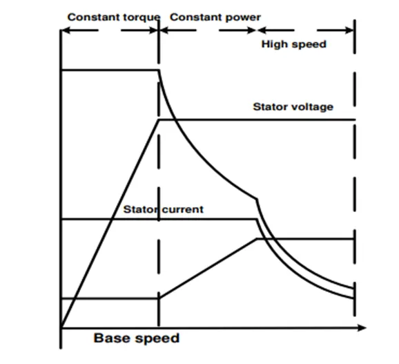
A different characteristic of Induction Motor
3.2 Permanent magnet brushless DC motor (PM-BLDC)
These are permanent magnet motors with no brushes. Because there is no rotor in the induction motor, it has a higher efficiency and less losses. Figure illustrates the characteristics of PMBLDC. It is characterised as a brushless since it does not have any brushes attached to it.
motor. A direct current (DC) source is provided to the stator, which produces a permanent magnet, which generates a field of magnetism The interplay of this magnetic field causes the rotor to rotate. The coil of the stator is influenced by Because of the back EMF, the torque decreases while the speed increases because of the current in the stator increases. Because it employs a permanent magnet, coil reduction becomes more expensive. Because regulating a PMBLDC motor is complex, its applications are limited, although this is not the case with square wave motors. To operate a BLDC motor, a complicated electrical circuit is necessary, and the motor's location must be understood for better control. In most industries, such PM BLDC motors with higher power density and efficiency than SRM and IM are used. They are employed in a variety of automobile components, including actuators.
- It can be utilized in the electric motor drive due to its high power and efficiency. The PM brushless motor drive differs from traditional motor drives in several ways.
- They are built in such a way that the coil span and slot pitch are equivalent, which reduces the superfluous part, resulting in a savings in volume and weight.
- When compared to a combinational PM brushless motor, the fractional number of slots per pole creates a consistent magnetic field between the stator and rotor, reducing cogging torque.
- The use of phase-decoupling increases the efficiency of the motor and improves its performance. Constant power operation is not possible in traditional motors. As a result, this method is used to achieve constant power operation at high speed.
- Either sinusoidal or rectangular input can be fed to the motor but sinusoidal fed has the advantage of smooth torque because of sinusoidal current and sinusoidal flux interaction.
3.3 BLAC
Because of its high power density and efficiency, many vehicle manufacturers currently utilize this type of motor in their vehicles. However, because these motors have a low power region, a conduction angle power converter is employed, which provides a wider speed range and increases efficiency.
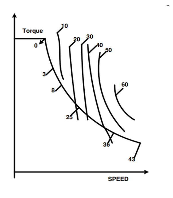
Torque speed characteristic of BLAC Motor
2.4 DC Motor
DC motors are another type of motor that can be utilized in electric cars. It features a straightforward design and is built to last. Due of its low efficiency, the brushed DC motor cannot be utilized in automobiles because of its high torque and extremely low speed. It is less dependable and necessitates more maintenance, which raises the expense. Friction between the brush and the collection reduces its efficiency. Figure depicts the torque-speed characteristic.
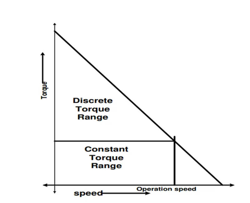
Torque Speed Characteristic of Brushless DC Motor
3.5 Switched Reluctance Motor (SRM)
It is sometimes referred to as a doubly salient machine. Because the stator and rotor are formed of iron, they are both magnetic in this motor. Torque is generated to reduce the air gap. The disadvantages of this motor are that it is difficult to turn on and off because the stator current cannot be easily adjusted. To lessen the noise produced by the stator, the number of coils must be increased. Because of its simple and sturdy construction, the switched reluctance rotor may be utilised in electric cars and can be operated at very high speeds without causing damage, as seen in figure below.
Torque Speed Characteristic of Switched Reluctance Motor
4.SELECTION OF MOTOR
4.1. MOTOR CONTROLLER
A motor controller is a device or collection of devices that govern the functioning of an electric motor in a predetermined manner. A motor controller may comprise manual or automatic ways of starting and halting the motor, selecting forward or reverse rotation, selecting and regulating speed, limiting or regulating torque, and guarding against overloads and faults. We are employing a "sine wave vector controller" in this project. The motor controller block is linked to the battery block. The motor controller, which is the system's central component, regulates all functional capabilities. The essential necessity for control, especially for DC motors, is to manage the amount of power given to the motor. The motor controller can be programmed to sync with other brushless motors. The use of a motor controller was used to drive and control the BLDC motor. The motor controller is a must-have component for any motor-driven device. The motor controller functions similarly to the human brain, processing information and relaying it to the end user. Of course, the applications of a motor controller differ depending on the work that it will accomplish. One of the most basic applications is a simple switch that supplies power to the motor, causing it to run. The complexity of the motor controller grows as more features in the motor are used. Field-Oriented Control (FOC), also known as a sine wave vector controller, is a vital technology for motor systems, particularly those that use permanent magnets (PM). In general, FOC provides an effective approach to regulate a BLDC motor in variable speed drive applications with rapidly changing loads, and it can increase a BLDC motor's power efficiency.
4.2.BLDC HUB MOTOR
The use of the permanent magnets(PM) in electrical machines in place of electromagnetic excitation results in many advantages such as no excitation losses, simplified construction, improved efficiency, fastdynamicperformance and high torque or power per unit volume.
A brushless direct current (BLDC) motor is a synchronous electric motor that is powered by direct current electricity (DC) and includes an electronically controlled commutation mechanism rather than a mechanical commutation system based on brushes. In ssuch motors, current andtorque, voltage andrpmare linearly srelated. The electromagnets in a BLDC motor do not move; instead, the permanent magnets rotate while the armature remains stationary. The architecture of a modern brushless dc motor is remarkably similar to that of an alternating current motor, often known as a permanent magnet synchronous motor. The structure of a typical three phase brushless dc motor is depicted in the figure below. The windings in the stator are identical to those in a polyphase ac motor, while the rotor is made up of one or more permanent magnets. Brushless dc motors differ from ac synchronous motors in that the former has some mechanisms to detect rotor position or (magnetic poles) to produce signals to regulate electronic switches. The hall element is the most common position/pole sensor, but other motors use optical sensors.
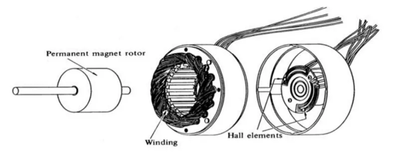
Disassembled view of a brushless DC motor
Although three-phase motors have the most outer box and efficiency, two-phase brushless dc motors are also widely utilized for easy construction and drive circuits. The figure below depicts cross-sections of a two-phase motor with an auxiliary salient pole.
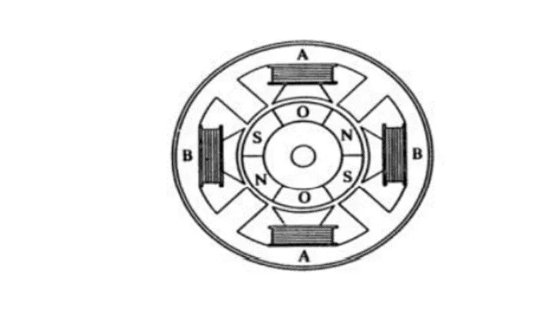
Two-phase brushless dc motor
5. POWER RATING OF VEHICLE
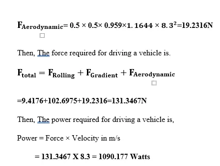
Vehicle dynamics such as rolling resistance, gradient resistance, aerodynamic drag, and so on must be considered when determining a vehicle's power rating. The technique for determining a motor rating for an electric scooter with a gross weight of 220 kg.
The force required for driving a vehicle is calculated as:
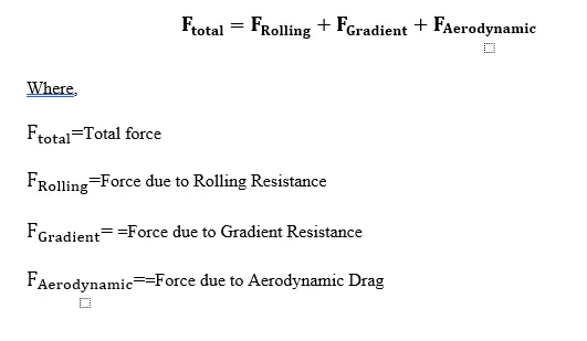

5.1. ROLLING RESISTANCE
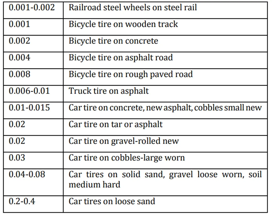
The resistance provided to the vehicle by the tire's contact with the road is known as rolling resistance. Equation gives the formula for determining the force due to rolling resistance.
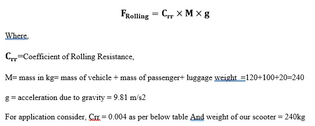
5.2 GRADIENT RESISTANCE
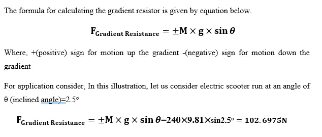
Gradient resistor of the vehicle is the resistance offered to the vehicle while climbing a hill or flyover or while travelling in a downward slope. The angle between the ground and slope of the path is represented as θ which is shown in below figure
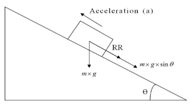
Free Body Diagram of a Vehicle moving up an Inclined surface.
5.3. AERODYNAMIC DRAG
Aerodynamic drag is the resistive force offered due to viscous force acting on a vehicle. It is linearly determined by the shape of vehicle. The formula for calculating aerodynamic drag is given by below equation
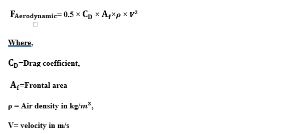
For application consider, maximum speed of our scooter is 30 kmph (given) that is 8.3m/s and air density is 1.1644 kg/m3 at 30 degree temperature and drag coefficient is 0.5 , frontal area is 0.959m2
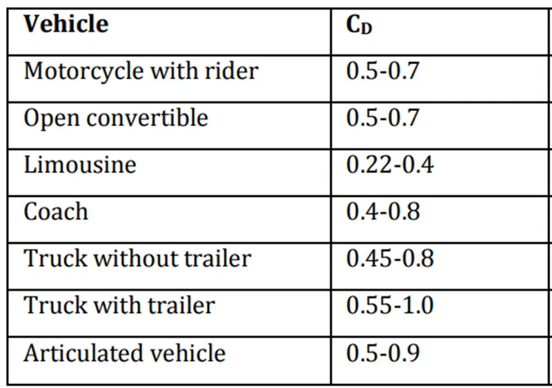
Drag coefficient and frontal area of vehicle
6.SELECTION OF HYDRAULIC CYLINDER AND CALCULATION
A hydraulic cylinder is a motor that uses a working fluid, a piston-type operating principle, and back-and-forth motions to operate. Hydraulic motors have a wide range of applications. Hydraulic motor powered mechanisms are utilised in forging presses, lifters, pumps, construction, and machine manufacturing, among other places where a strong motor is required. Hydraulic cylinders (LINK) are available in a variety of configurations and action types:
A hydraulic circuit is a collection of components such as pumps, actuators, and control valves that are arranged in such a way that they perform a useful duty. When studying or developing a hydraulic circuit, the three main elements listed below must be taken into account. take into consideration:
- Operational safety
- Implementation of required function
- Operational effectiveness
It is critical for the fluid power (Hydraulics and Pneumatics) designer to understand the components and how they perform in a circuit. Hydraulic circuits are created by using graphical symbols for all components.
6.1 Single - Acting Hydraulic Cylinder:
A single-acting cylinder can exert a force in only the extending direction as fluid from the pump enters the blank end of the cylinder ( usually left side of the piston). Single- acting cylinder do not retract hydraulically. Retraction is accomplished by using gravity or by the inclusion of a compression spring in the rod end
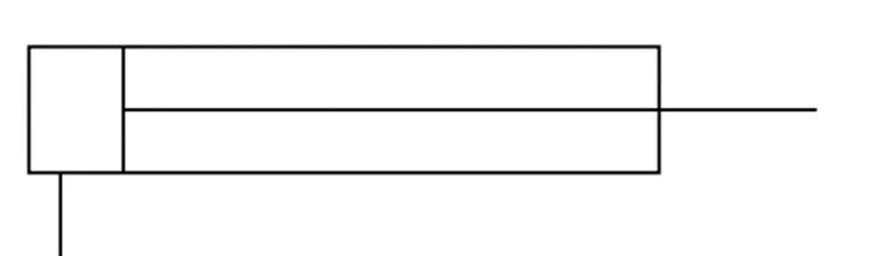
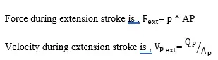
Because single – acting cylinders do not retract hydraulically, the force and velocity during the retraction stroke are determined by the spring rate.
A two- postion, three way, manually operated, spring offset directional control valve ( DCV ) used to control the operation of a single – acting cylinder. In the spring offset mode, full pump flow goes the tank via the pressure relief valve. The spring in the rod end of the cylinder retracts the piston as oil from the blank end ‘A’ drains back to the rank. When the valve is manually actuated the pump flow goes to the cylinder blank end ‘A’ via DCV 1 position. This extends the cylinder. At full extension, pump flow goes through the relief valve. Deactivation of the DCV allows the cylinder to retract as the DCV shift into its spring – offset mode
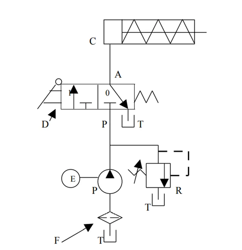
Control of Single -Acting Hydraulic Cylinder
C = Single acting cylinder
P = Pump
E = Electric Motor
T = Tank
F = Filter
R = Relief Valve
D =2-position, 3 way DCV Manually operated and spring return
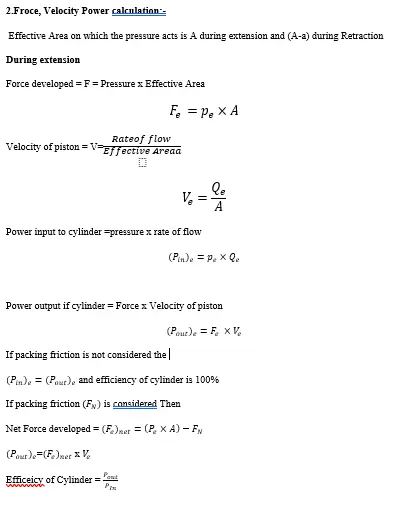
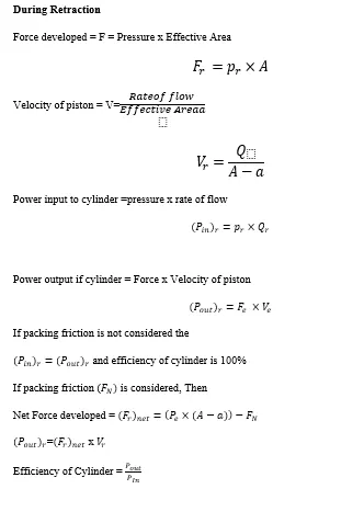
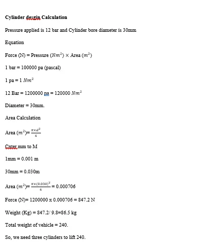
6.1. CYLINDER CALCULATIONS
D= Diameter of the piston or bore diameter of cylinder
d= Diameter if piston rod
F=Force in m/s
Q= Discharge in m3/s
P = power in watts
p= pressure in N/m
1.Packing Friction
- The minimum amount of force which is required to move the position in cylinder under no load condition is called as Packing friction.
- In this case the position is tightly inserted in the cylinder. Due to rubber piston seals and tight fitting, it requires some amount of force just to move the piston
- Generally, packing friction is considered to be same for both extension and retraction. That is, same amount of force is require to pull as well as to push the piston in the cylinder under no-toad.
- Net force required = working load + packing friction
7.DESIGN AND DEVELOPMENT OF STEP CLIMBING
Traditional wheelchairs and powered wheelchairs continue to play an important role in mobility. However, wheelchairs currently give a high level of mobility only in artificial or barrier-free situations. Thus, there remains a significant gap between the obstacle negotiating ability of a wheelchair and that of the average able person. This aspect is perhaps most apparent when considering stair-climbing. Current common practice in regard to stair assistance is that two to four assistants are required for a mobility of disabled person say in a wheelchair to negotiate a set of stairs. Assistive device based solutions for stair-negotiation includes lifts and chair or platform based stair-lift mechanisms. Stairs perhaps best represent “environs not suited to wheeled vehicles”. Two fundamental means of stair negotiation are provision of a stepping mechanism, or increasing the wheel’s footprint (diameter) so that the step is bridged. Provision of a stepping mechanism requires relatively complex mechanical operation and must be linked to knowledge of the location of the stair edge.
Although there are universal standards for providing ramps, lifts, and escalators in all public buildings these days, it is recognised that they are not ubiquitous due to space constraints and other factors.
Tank Mechanism: This mechanism It is similar to a tank and consists of a tracked undercarriage attached to the underneath of the scooter.
The undercarriage truss is designed to allow for simple ascent and descent. Motors move the track through gears to ensure adequate reduction. The belts are comprised of a metal-and-rubber composite material. The truss has a 120 cm base length for aesthetics and ease of operation. Within the size limits, the material should have the highest stress-bearing capacity.
Thus, when the aforementioned factors of consideration are taken into account, mild steel is a promising material for truss material.
Composites with metal chain for structural stiffness and rubber for the requisite coefficient of friction and traction for smooth ascent and descent on stairs are preferred for the belt material. This composite provides the required balance of strength and flexibility. The rubber provides the friction.
7.1 DESIGN PARAMETERS
Walking patterns that appear to minimise energetic cost are chosen by humans and other animals. They tend to move at a speed close to that which minimises the metabolic energy cost per unit distance travelled. And, at a given speed, the nervous system chooses a combination of step frequency and step length that corresponds to the lowest rate of metabolic energy expenditure. The minimum ideal pace while walking on a level surface is 0.35m/s; however, due to the impediment of stepping while handling a wheelchair, the speed has been assumed to be 0.2m/s.
Because the wheelchair will be utilised for medical purposes, the mechanism must be exceptionally stable even in the most adverse conditions. The wheelchair must be affordable to the greatest number of people in developing countries such as India, and the price must not be prohibitively expensive. The mechanism must produce constant positive lift in order to rise or descend in a fair amount of time, which is dependent on the number of contacts. While ascending, contacts with four steps are assumed. The mechanism must be dependable in order to be employed in medical applications.
One assistant, in addition to the patient, has been proposed for higher climbing operation reliability. The wheelchair's combined weight with the patient is believed to be 200 kg. The pressures operating on the mechanism, as well as the forces caused by chain tension and gear transmission, are significant. As a result, these are computed and utilised to construct the shaft, bearing, chain, and sprocket.
7.2 Sprocket & Chain
Forces on Sprocket:
Tension acts on the shaft due to the chain drives.
This force is calculated as follows. Two motors
of 800 watts each.
Therefore, 800 watts for each chain drive.
P = F V (1)
P = Power = 800 Watts, V = velocity = 0.2m/s,
F = Force = 4000 N
By assuming a tolerable staircase ascending speed of one step per second, we get a linear speed of 0.2 m/s for the wheelchair. Given the losses and initial starting torque requirements, two 800 watt motors can be employed. We discover the best sprocket size for beginning climbing traction by trial and error, which is 20mm in diameter.
The RPM required at sprocket is calculated as follows:

Where 'V' is the linear velocity of the belt, 'D' is the diameter of the sprocket, and 'N' is the number of rotations per minute (RPM). With the above parameters, the RPM should be 20 rounded off to the nearest standard value. Following the selection of the chain, the following step is to select the sprocket. This is accomplished by utilising the chain's pitch. The tooth correction factor is appropriately updated based on the number of teeth, and then chain and sprocket computations are performed.
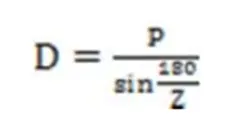
For z = 24 we have D = Diameter=194.5 mm Therefore, z = 24 is appropriate.
Taking tooth correction factor for 24 teeth as
we have,
Chain type-16A, Sprocket type 16A, Number
of teeth= 24
Considering forces on sprocket,
Vertical Force = Fv = 735.8N,
Horizontal Force = FH = 3931.9N
Analysis of Chain and Sprocket: For our particular application we use the following values from standard charts: Service Factor Ks=1.4 for heavy loads, Number of Teeth = z = 17, Tooth Correction Factor K1=1 for 17 teeth, Strand Factor K2=1 for 1 strand.
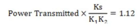
For kW = 1.12 and RPM = 20 we have from the charts Chain Type -12A, Pitch = P= 3/4 inch
Shaft: Shafts are equipped with steps for properly spacing the bearings and sprockets. The specifications that are crucial for the push-fit with bearings are meticulously machined.
Tensioner: A tensioner is a component that is present to facilitate chain drive assembly. The chains must be properly tensioned in order to perform properly. In addition, the chains should be simple to attach and detach from the sprockets. A slotted plate is provided, and the sprocket can be inserted in the desired position on the slotted plate. The design provides for 30 mm of axial adjustability.
8. CAD DESIGN OF STEPS CLIMBING SCOTER.
8.1. DESGIN METHODOLOGY
Stages involved in the Design of the Steps climbing Scotter are as Follows
- Benchmarking
- Concept sketching
- Concept Validation
- New product design using CATIA V5.
1.Benchmarking
Benchmarking is the practise of comparing the performance of a firm's products, services, or procedures to those of another company that is regarded as the best in the industry, or "best in class." Benchmarking is used to find internal opportunities for improvement. You may implement changes that will generate significant benefits by analysing firms with outstanding performance, breaking down what makes such superior performance feasible, and then comparing those procedures to how your business runs.
This could include modifying a product's features to more closely match a competitor's offering, changing the scope of services you provide, or implementing a new customer relationship management (CRM) system to enable more personalised communications with clients.
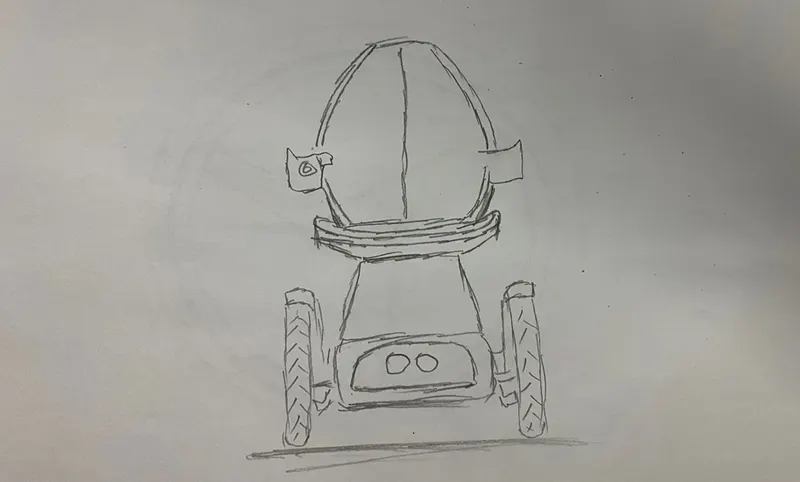
2.Concept sketching.
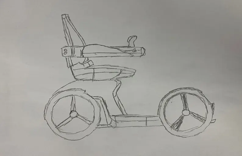
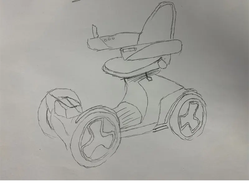
The importance of sketching in idea design is identified, and the circumstances of car design are outlined. It is offered a summary of work in the general subject of concept sketching and visual thinking. The qualities of vehicle design sketches are presented, including form lines, crown lines, area lines, shading, and colouring, as well as a de-layering analysis. In the vehicle design sketch, this highlights the importance of form lines
Side View
Isometric View
Back view
4.New product design using CATIA V5.
Catia Tools used in this project
Sketch Tools
- Line
- Profile
- Rectangle
- Circle
- Arc
- Trim
- Mirror
- Offset
- Project 3D elements
Tools Used in Part Work bench.
- Pad - In most CAD software, the equivalent of this is called EXTRUDE, but in CATIA we call it PAD. This command adds material in the third direction, a direction other than the sketch
- POCKET command – POCKET commands are the polar opposite of PAD commands. It merely aids in the removal of geometry from a previously created element. The POCKET command is used to help build the cylinder hole in the middle of the cube in the image below.
- SHAFT command- The SHAFT command, similar to the revolve command in other CAD software, is mostly used to create shaft-like elements. It necessitates the creation of an axis around which the sketch will be rotated.
- Fillet- this command is used to convert sharp corners to round corners with some radius
- Thicken- surface is thicken into part with a required thickness
- Split- by using this tool part can be split using surface
- Translate- using this command part can be translated
- Circular Pattern – This tool is sued to copy the parts in circular passion with a required instance.
Tools Used in Surface Work bench.
- Extrude- using this command sketch is extruded into rsurface
- Extract- Using this command we can extract the boundaries or copy the surface
- Offset- using this command we can offset surface to a required distance
- Trim- Suing this command we can trim unwanted surface and join
- Split- this can split surface but will not join
- Join- Can join to connecting surfaces
- Extrapolate- using this we can extent the surface.
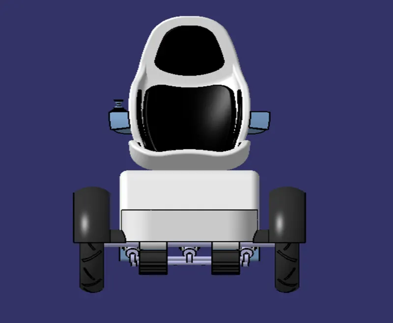
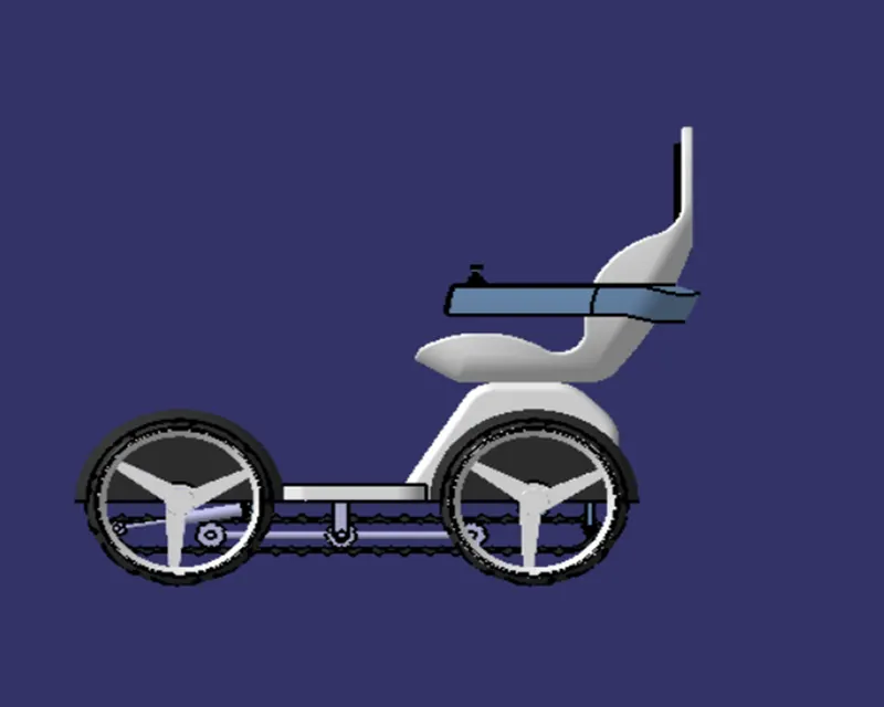
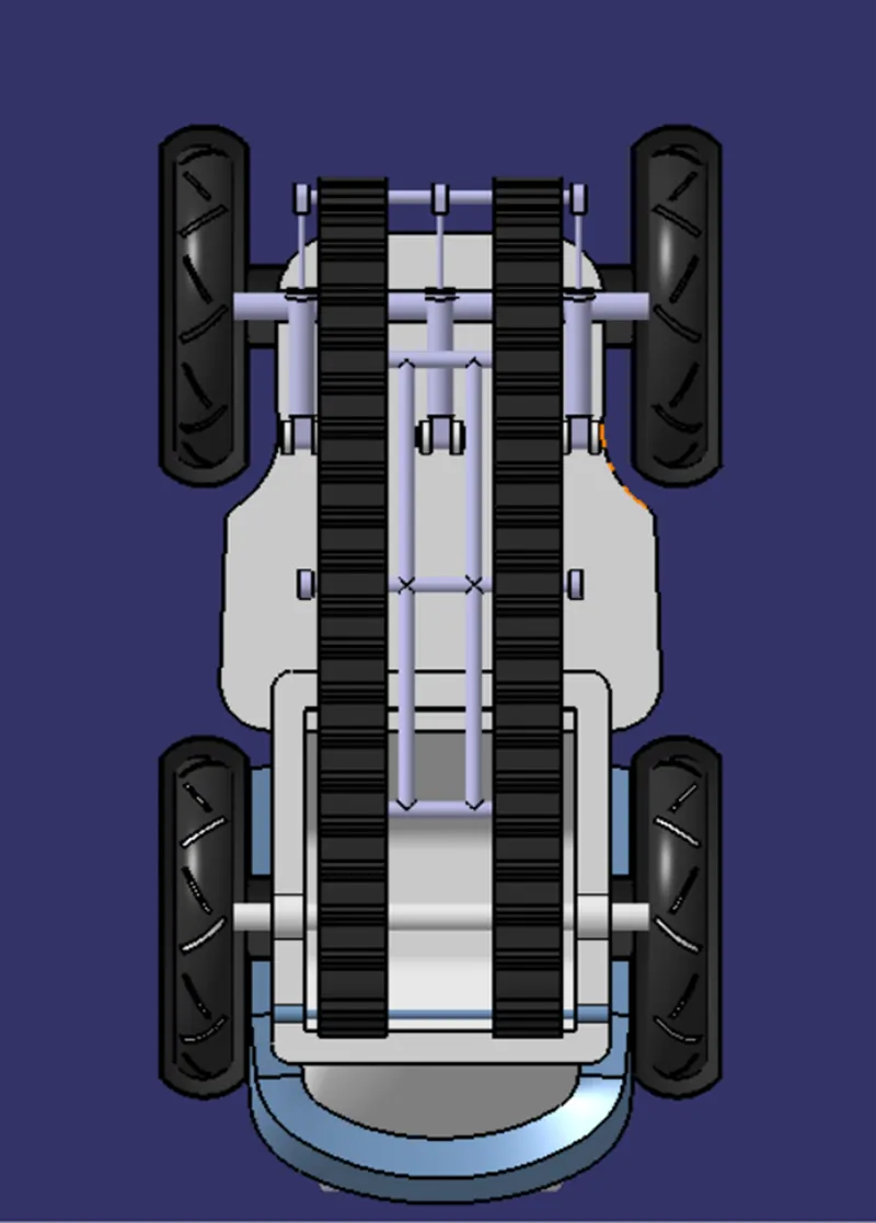
Different View of the model
Front View
Side View.
Back View
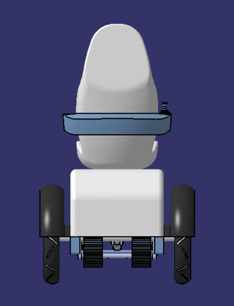
Bottom View
Isometric view
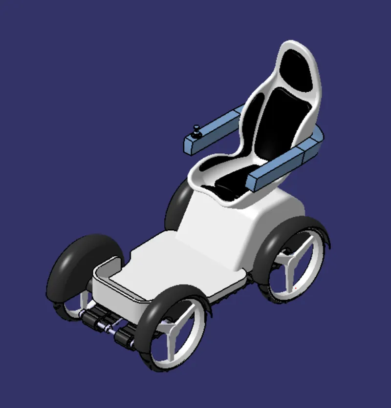
Working Principal
Working Principal When the pumps are activated it pushes the wheel and the vehicle upwards and belt touches the ground and it will get a clearance to climb the steps
CONCLUSION: -
The various mechanisms were examined, and the most suited ones were thoroughly investigated. The tank mechanism was deemed to be the most suitable to meet the various requirements after comparing their relative advantages and limitations. CATIA software was used to model a. The steps climbing E scooter is designed using the different stages. Desgin and desired Calculations are made for motor and cylinder and rubber track belt
References
[1] Nanda, G. and Kar, N.C., “A survey and comparison of characteristics of motor drives used in electric vehicles”.In 2006 Canadian Conference on Electrical and Computer Engineering (pp. 811-814), 2006.
[2] De Santiago, J., Bernhoff, H., Ekergård, B., Eriksson, S., Ferhatovic, S., Waters, R., &Leijon, M., “Electrical motor drivelines in commercial all-electric vehicles: A review”.IEEE Transactions on vehicular technology, 61(2), 475-484, 2012.
[3] Momoh, O.D. and Omoigui, M.O., “An overview of hybrid electric vehicle technology”.In 2009 IEEE vehicle power and propulsion conference, pp. 1286-1292, 2009. [4] Chan, C.C. and Chau, K.T., “Modern electric vehicle technology”. Oxford University Press on Demand, Vol. 47, 2001.
[5] Chan, C.C., Chau, K.T., Jiang, J.Z., Xia, W.A.X.W., Zhu, M. and Zhang, R., “Novel permanent magnet motor drives for electric vehicles”. IEEE Transactions on Industrial Electronics,43(2), pp.331-339, 1996.
[6] Rahim, N.A., Ping, H.W. and Tadjuddin, M., “Design of axial flux permanent magnet brushless DC motor for direct drive of electric vehicle”.In 2007 IEEE Power Engineering Society General Meeting, pp. 1-6, 2007.
[7] Ehsani, M., Gao, Y. and Gay, S., November. “Characterization of electric motor drives for traction applications”. In IECON'03.29th Annual Conference of the IEEE Industrial Electronics Society, IEEE Cat.No. 03CH37468, Vol. 1, pp. 891-896 2012.
[8] West, J.G., 1994. “DC, induction, reluctance and PM motors for electric vehicles”. Power Engineering Journal, 8(2), pp.77-88, 2003.
[9] Riba, J.R., López-Torres, C., Romeral, L. and Garcia, A.,“Rare-earth-free propulsion motors for electric vehicles: A technology review”. Renewable and Sustainable Energy Reviews, 57, pp.367-379, 2016.
[10]Murray John Lawn, Study of stair-climbing assistive mechanisms for the disabled, PhD Thesis, Japan, (2002).
[11]Kan Yoneda, Yusuke Ota, Shigeo Hirose, Stair Climbing Robots and High Grip Crawler, In Tech Publishers, (2010).
[12]Lawn MJ, Ishimatsu T. Modeling of a stairclimbing wheelchair mechanism with high single-step capability. IEEE Trans Neural Syst Rehabil Eng. Volume 11, issue 3, (2003), 323- 332.
[13] R Rajasekar, K P Pranavkarthik, R Prashanth, S Senthil Kumar and A Sivakumar, Design and Fabrication of Staircase Climbing Wheelchair, IJMRRR, (2013), 320-323. [14]Ralston H J., Energy speed relation and optimal speed during level walking, Int Z Angew Physiol (1958) 277-283.
[15]Mark Snaterse, Robert Ton, Arthur D. Kuo and J. Maxwell Donelan. Distinct fast and slow processes contribute to preferred step frequency during human walking, J Appl Physiol (2011), 1682-1690.
[16] Lin Zhang, Xi Feihong, An optimization design for the stair climbing wheelchair, M.Sc. Thesis, Blekinge Institute of Technology, Sweden (2012).