Advanced Sheet Metal Design Using NX Cad Challenge_7_ Metal bracket-II
DESIGN and MODELLING of SHEET METAL BRACKET-2 BY USING SHEETMETAL APPLICATION in NX-12
Objective:
# Using some basic features and tools, design and model the sheet metal bracket-2 in NX-12.
# To learn how to create a sheet metal bracket-2 from a drawing.
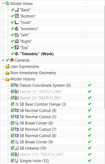
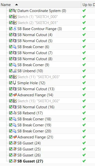
# To become familiar with the user interface and basic features of the Sheetmetal application in NX-12, such as Contour flange, Normal Cut-out, Break corner, Unbend, Bead, Rebend, Hole, Advanced flange, and Gusset.
Introduction: -
# Sheet Metal Fabrication is the process of forming parts from a metal sheet by punching, cutting, stamping, and bending.
# 3D CAD files are converted into machine code, which directs a machine to precisely cut and shape the sheets into the final part. Sheet metal components are known for their durability, making them ideal for end-use applications (e.g. chassis). Due to high initial setup and material costs, parts used for low volume prototypes and high volume production runs are the most cost-effective.
# Because parts are made from a single sheet of metal, designs must be consistent in thickness. To ensure that parts are closer to the design intent, adhere to the design requirements and tolerances when cutting metal sheets.
Design Methodology / Approach:-
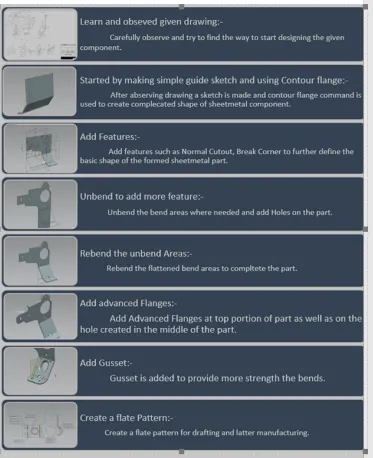
1. Contour Flange– The contour flange command in Siemens nx sheet metal is used to create a base feature by extruding a sketch along a vector, or to add material by sweeping a sketch along an edge or chain of edges.
2. Normal Cutout – Using sheet metal production principles, the Normal Cutout command extracts volumes from sheet metal. Cutting faces will be perpendicular to the surface of the sheet metal.
3. Break Corner– This feature is used to smooth out the sheet's harmful corners or to give the part a more appealing appearance.
4. Unbend– This feature is used to flatten the sheet metal part before proceeding with the design.
5. Rebend– The Rebend feature is used to restore the original bend shape after forming operations such as a dimple or a bead.
6. Advanced Flange– Use this command to add a flange along an edge by specifying a bend angle or a reference face. Curved edges and reference faces are possible. This command is useful when working with sheet metal support structures in complex assemblies or when creating non-linear flanges.To define the flange dimensions, we can use existing geometry as a guide.
7. Gusset– A gusset is a stiffening feature that is created across a bend to reinforce the sheet metal part.
8. Flatt Pattern– This feature is used to generate an instance of the flat shape and size of the sheet metal needed to make the final part.
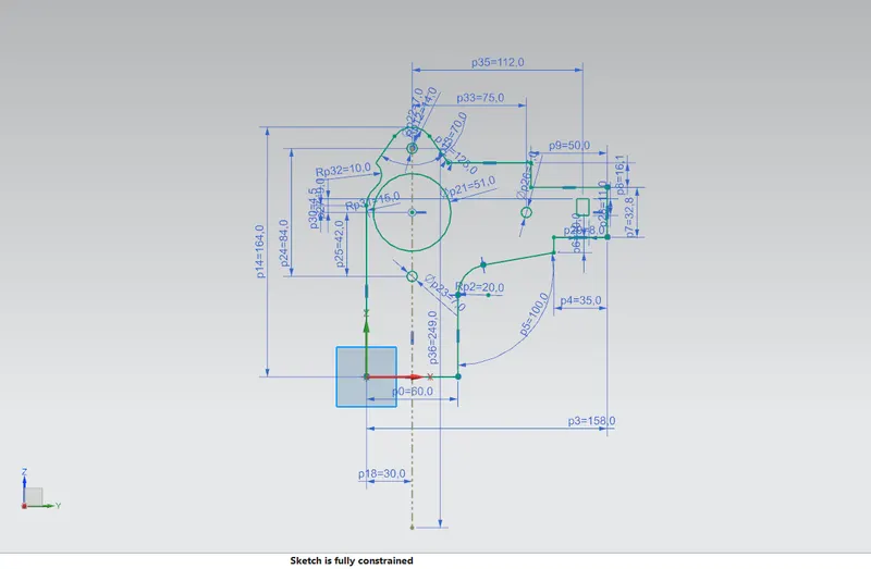
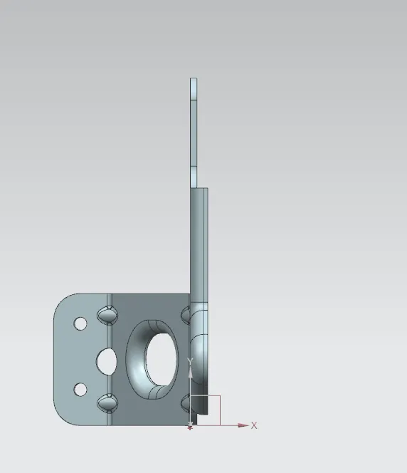
Front View,
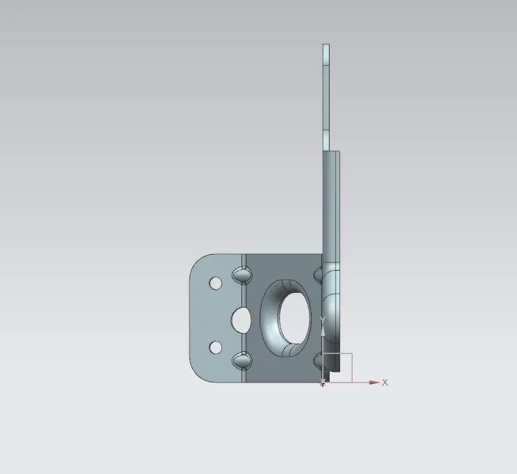
Side View,
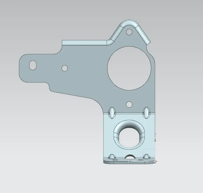
Isometric View
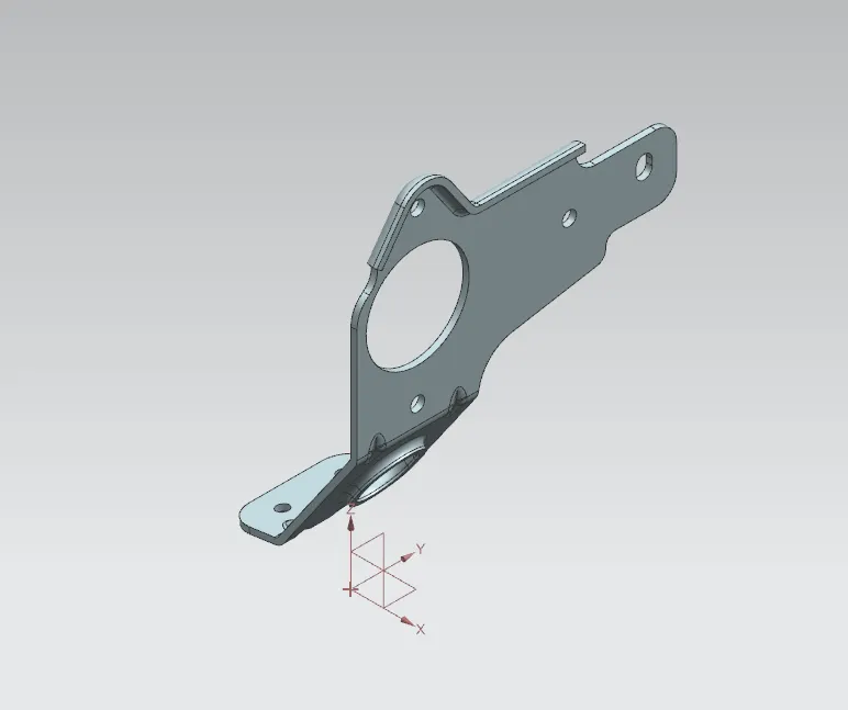
Top View