Week 6 - CHT Analysis on a Graphics card
Aim: To perform a steady state conjugate heat transfer analysis on a given model of graphics card.
Objectives:
- To Run the simulation by varying the velocity from 1m/sec to 5m/sec for at least 3 velocities and to discuss the results.
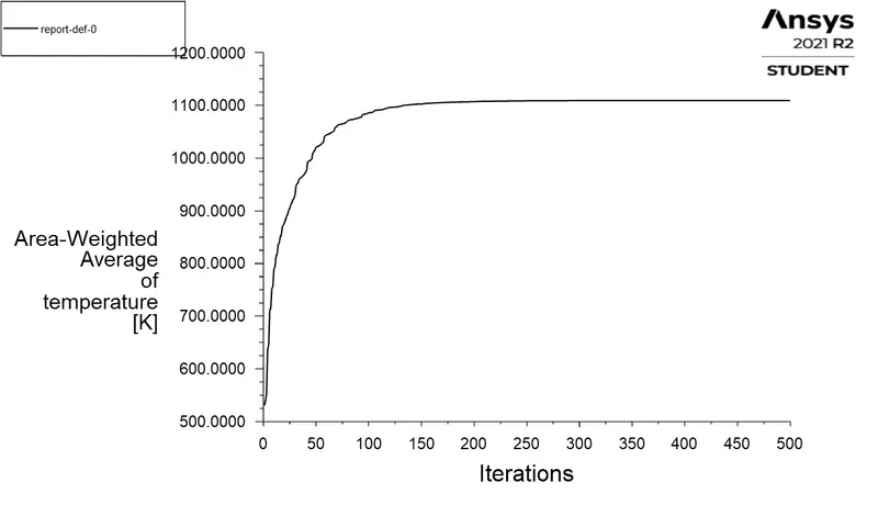
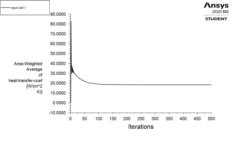
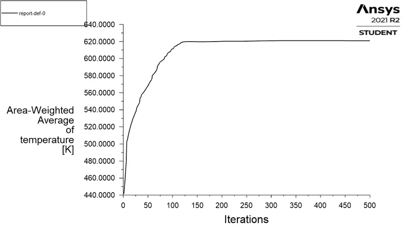
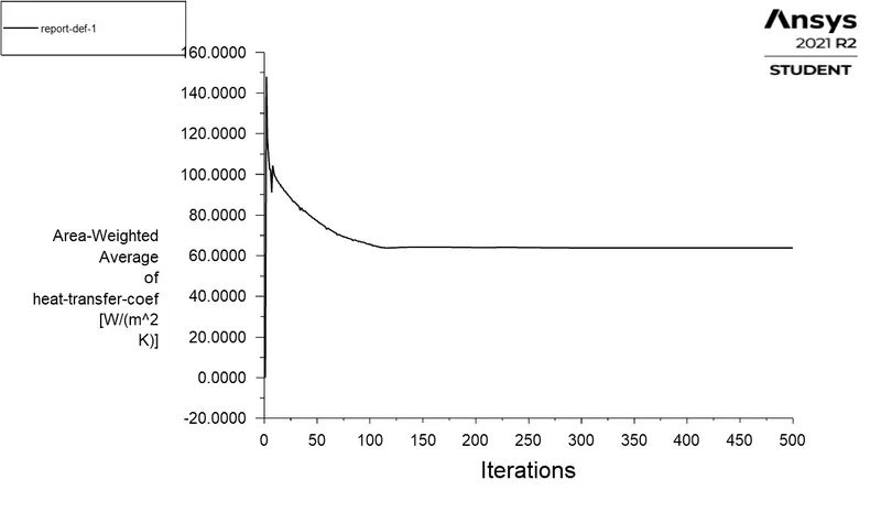
- To Find out the maximum temperature and heat transfer coefficient attained by the processor.
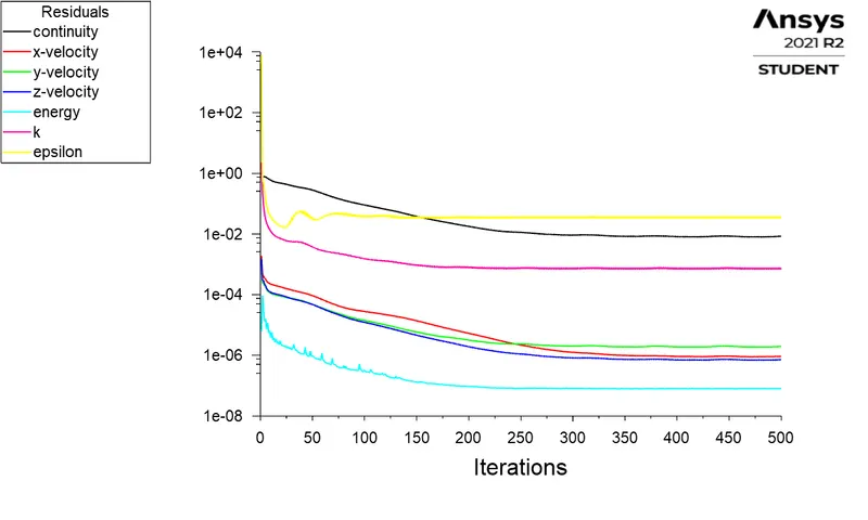
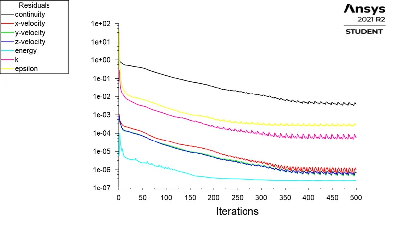
- To Prove that the simulation has achieved convergence with appropriate images and plots.
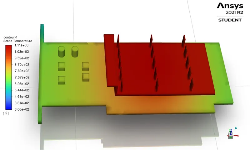
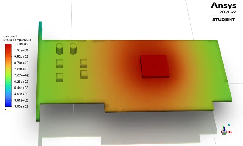
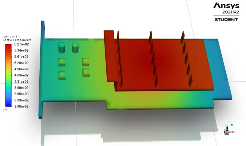
- To Identify potential hotspots on the model.
CHT analysis:
Whenever there is a heat transfer through solids and fluids simultaneously, the approach of solving the problem case through a set of transport equations on the basis of materials and given boundary conditions is known as the conjugate heat transfer (CHT) analysis.
The conduction is the dominant mode of heat transfer in solids while in fluids the convection is the dominant mode of heat transfer.
Heat Transfer in solids and fluids is combined in the majority of applications. As the solids are generally immersed in fluids the Conjugate Heat Transfer (CHT) analysis is very helpful in predicting the temperature distribution and heat transfer rates and their effects.
Graphics Card Model and Meshing details:
| Graphics card assembly with fins | Graphics card assembly without fins (Exposing Processor) |
||
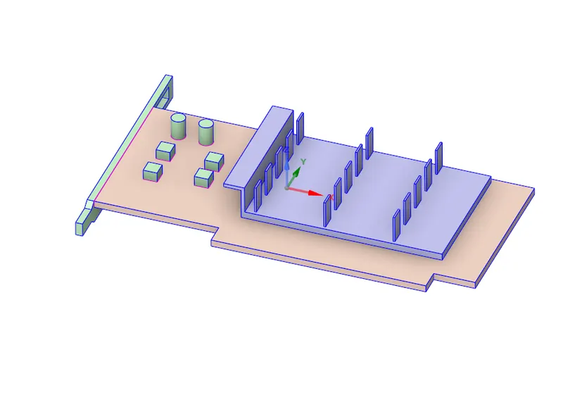 |
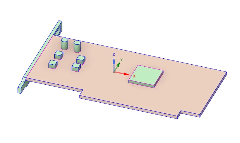 |
||
| Graphics card assembly with fins side view | Graphics card assembly with fins top view | ||
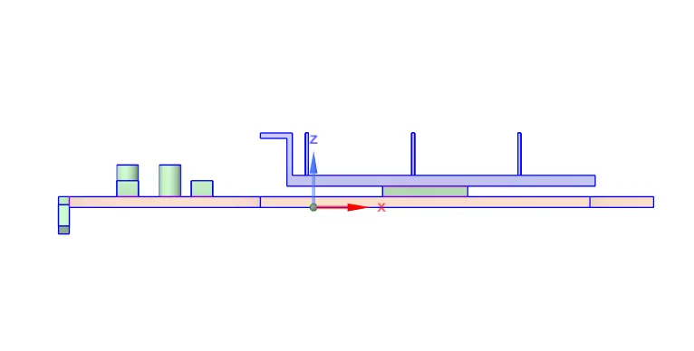 |
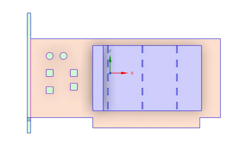 |
||
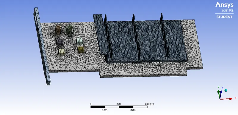
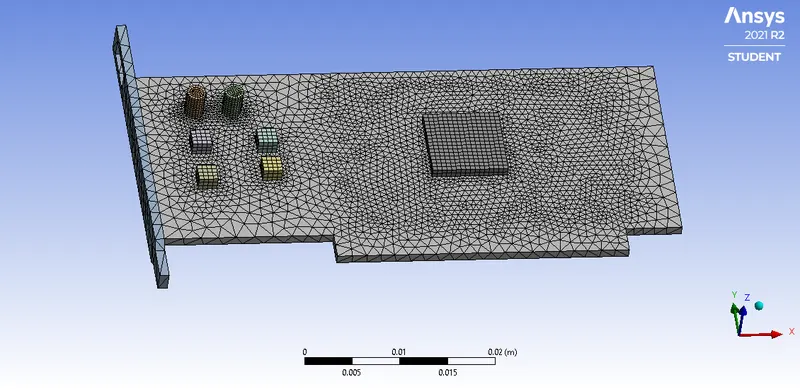
| Mesh of whole graphics card assembly | Mesh of graphics card assembly without fins | ||
 |
 |
||
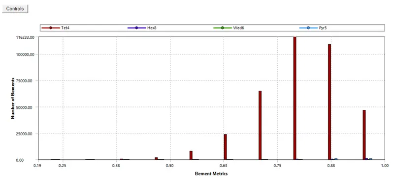
| Mesh Metrics | ||
 |
||
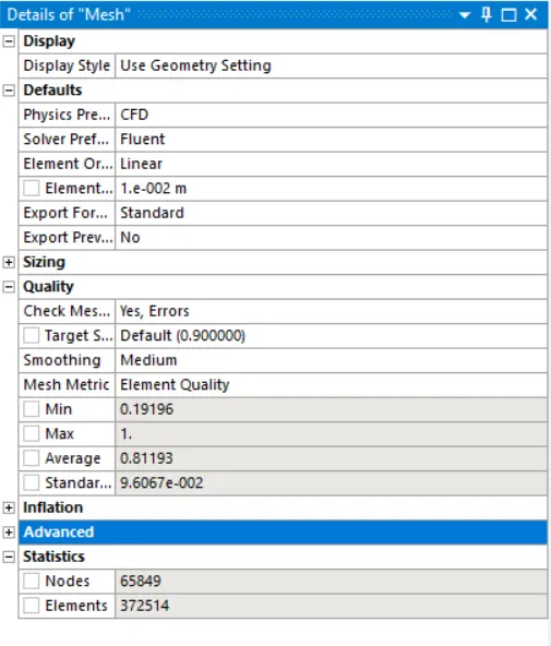
| Mesh Details | ||
 |
||
| Finer mesh is created on processors , finbase , capacitors and memorycards as these are the regions for the heat transfer. |
Case Setup details:
Solver: Pressure Based Steady State Solver ;
Solution Scheme: SIMPLEC;
Velocity : absolute ;
Viscous Model : k-epsilon (realizable model);
Boundary Conditions: inlet - velocity inlet ; outlet - pressure outlet.
The contact surface between processor and the finbase is considered as the thin wall with material of thermal paste.
Materials assigned for different parts of graphics card and their thermophysical properties:
| Sr. No. | Named Selection | Material Assigned |
Density |
Specific Heat Capacity `(J/((kg)*K))` | Thermal Conductivity `(W/(m*K))` | Viscosity `((kg)/(m*s))` |
| 1 | Fluid Zone | air | 1.225 | 1006.43 | 0.0242 | 1.7894 e-5 |
| 2 | Fins | aluminium | 2719 | 871 | 202.4 | - |
| 3 | Processor | silicon | 2330 | 770 | 170 | - |
| 4 | Basecard | pcb-composite | 2157 | 1117 | 20 | - |
| 5 | Memorycards | Memorycard-composites | 1900 | 1200 | 0.23 | - |
| 6 | Capacitors | tantalum | 16650 | 140 | 57.5 | - |
| 7 | Contact between processor and fins with assigned wall thickness of 1e-5 m. | thermal-paste | 4000 | 2000 | 2.5 | - |
Heat Source details:
The processor along with capacitors and memory cards are considered as the volumetric heat generation sources. Details are listed below
| Sr. No. | Heat Source | Volume of Heat source | Heat Generation Rate |
| 1 | Processor | 64 e-9 `m^3` | 50 W |
| 2 | Capacitors | 19 e-9 `m^3` | 0.1 W |
| 3 | Memorycards | 24 e-9 `m^3` | 0.1 W |
Results:
Case I: With air inlet velocity of 1 m/s.
| Residual Graph | Processor Temperature plot | |||
 |
 |
|||
| Area weighted average Heat Transfer coefficient for fins graphs | Temperature contour | |||
 |
 |
|||
| Potential Hot Spot | Temperature contours on sectional planes and solid zone | |||
 |
 |
|||
| Heat transfer coefficient contour | Velocity on sectional planes & Temp on solid zone | |||
 |
 |
|||
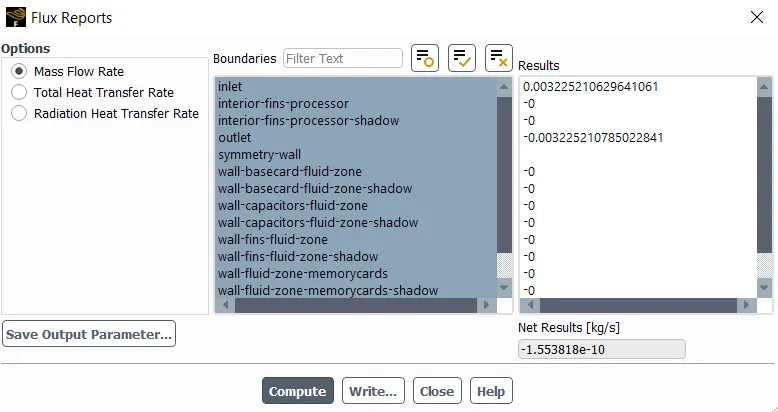
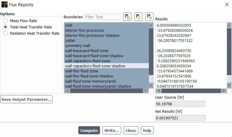
| Mass flowrate report | Heat flux report | |||
 |
 |
Case II: With air inlet velocity of 3 m/s.
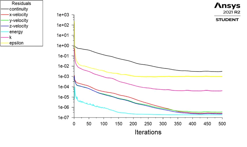
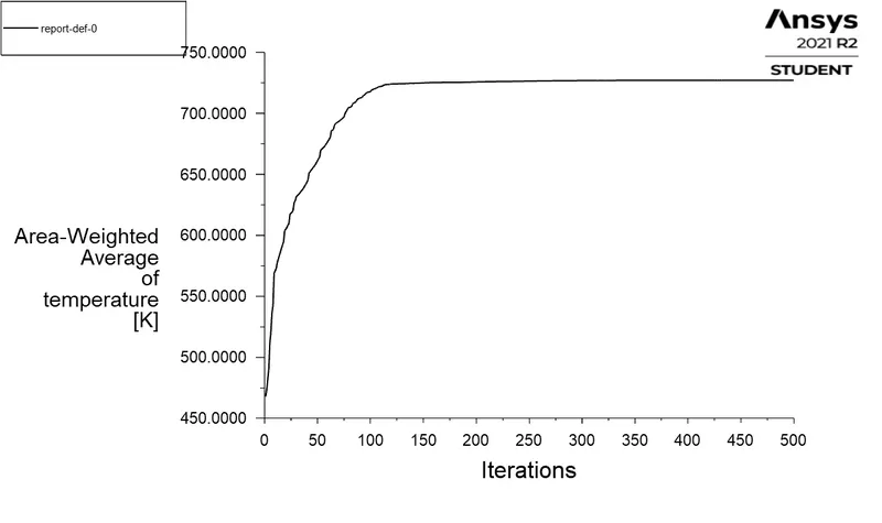
| Residual Graph | Processor Temperature plot | |||
 |
 |
|||
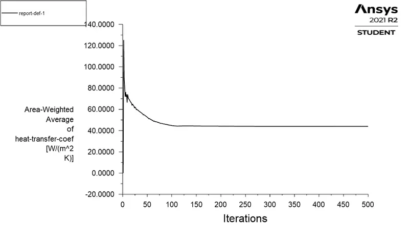
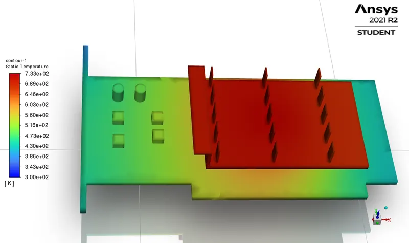
| Area weighted average Heat Transfer coefficient for fins graphs | Temperature contour | |||
 |
 |
|||
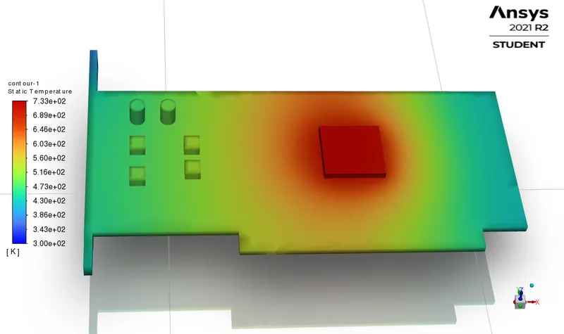
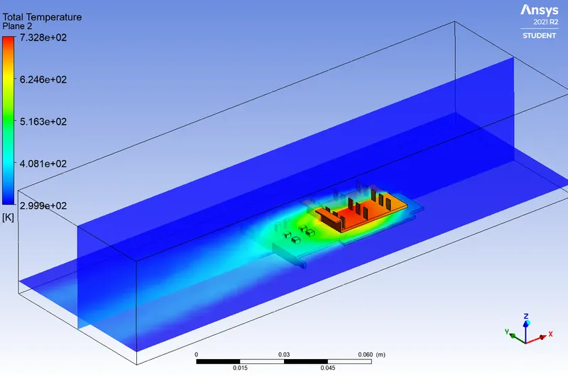
| Potential Hot Spot | Temperature contours on sectional planes and solid zone | |||
 |
 |
|||
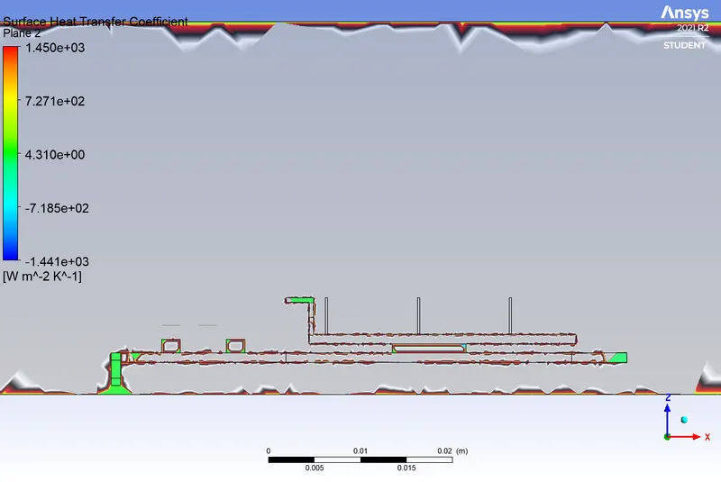
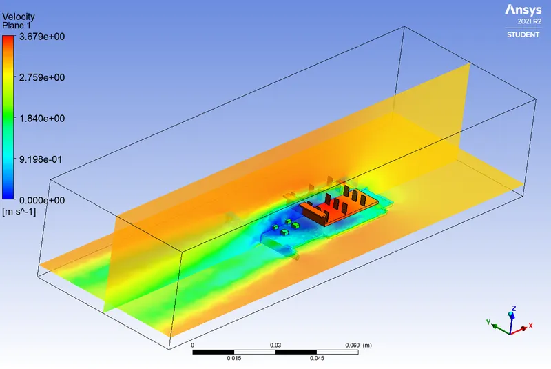
| Heat transfer coefficient contour | Velocity on sectional planes & Temp on solid zone | |||
 |
 |
|||
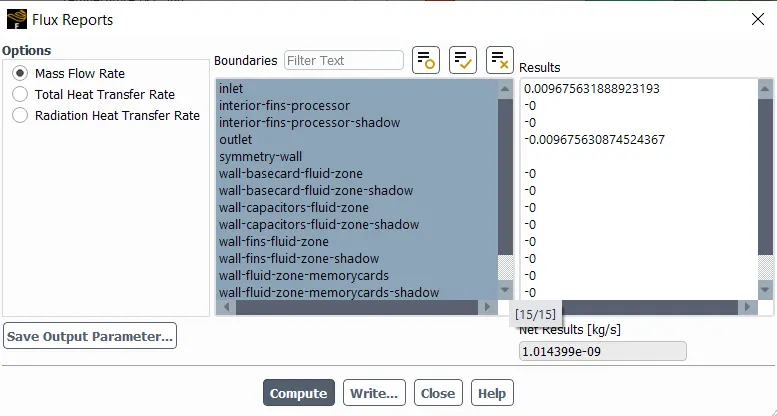
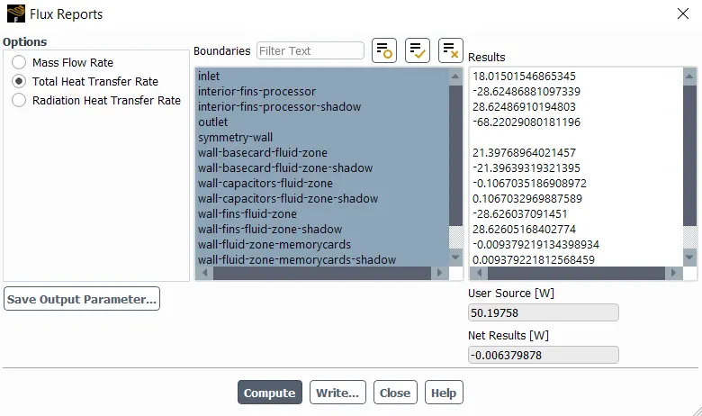
| Mass flowrate report | Heat flux report | |||
 |
 |
Case III: With air inlet velocity of 5 m/s.
| Residual Graph | Processor Temperature plot | |||
 |
 |
|||
| Area weighted average Heat Transfer coefficient for fins graphs | Temperature contour | |||
 |
 |
|||
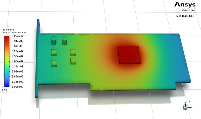
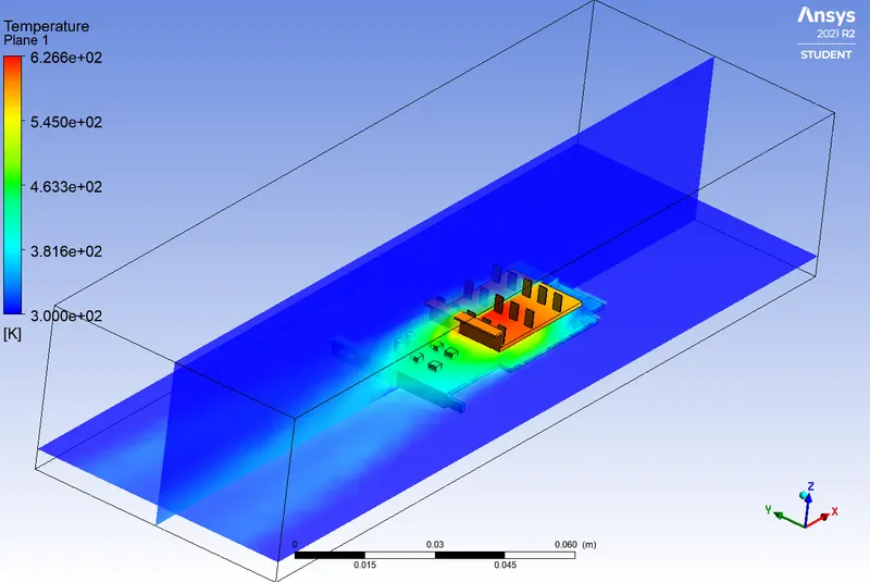
| Potential Hot Spot | Temperature contours on sectional planes and solid zone | |||
 |
 |
|||
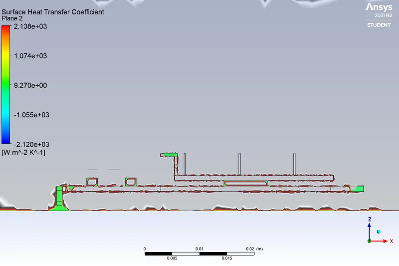
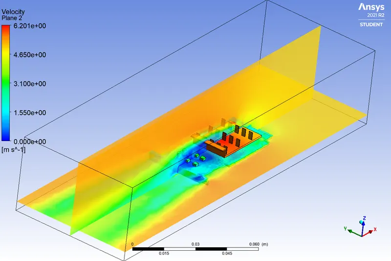
| Heat transfer coefficient graph | Velocity on sectional planes & Temp on solid zone | |||
 |
 |
|||
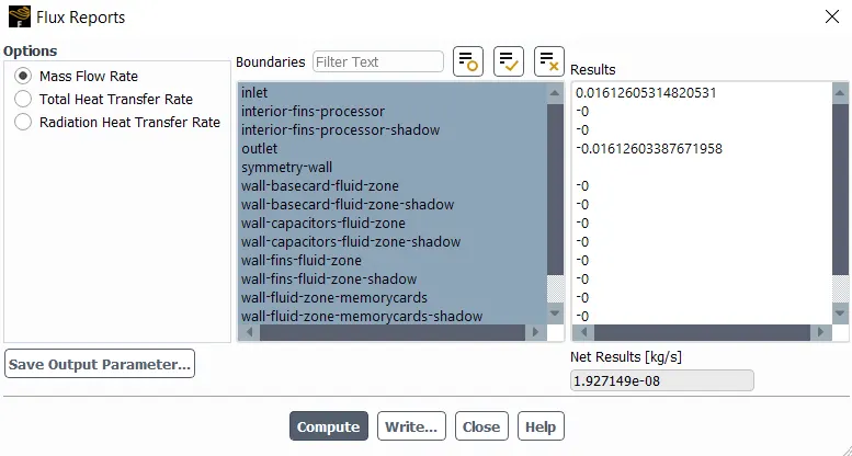
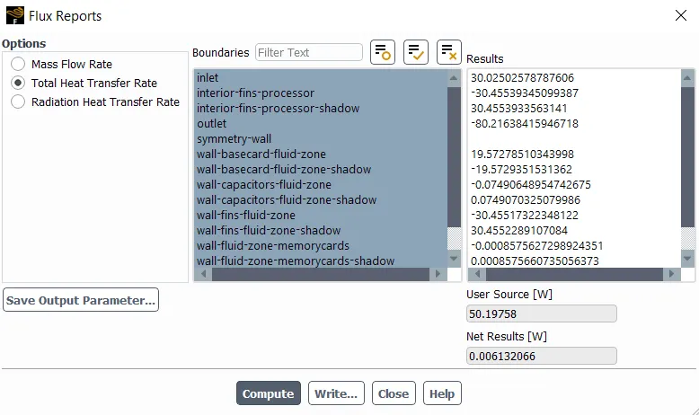
| Mass flowrate report | Heat flux report | |||
 |
 |
Observation Table:
The maximum temperature attained by processor and coefficients of heat transfer for processor , finbase , capacitors and memory cards is tabulated in the observation table.

Conclusions:
- The residuals graph and flux reports show that the solutions are converged.
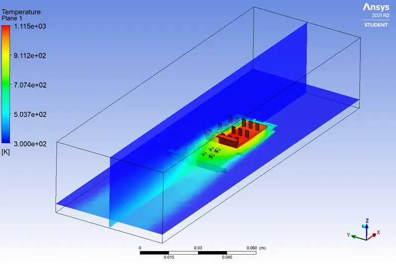
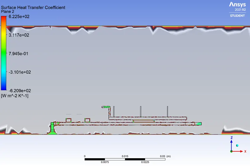
- The steady state CHT analysis of graphics card isdone with for air velocities of 1 m/s ; 3 m/s and 5 m/s are performed and results are represented as above. The trend of results is as expected that heat transfer rate increases with increase in air flow velocity. This can be observed from the heat transfer coefficient graphs and area weighted average of processor temperature graph as temperature is decreasing with increase in air flow velocity.
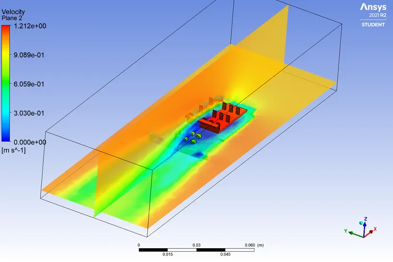
- Similar trend of increasing heat transfer rate is observed with capacitors but heat transfer rate of memory cards is decreasing with increase in air velocity this is mainly due to the increasing the low pressure recirculation zone created by increasing air velocity behind the finbase. This can be observed in the velocity contours in sectional planes.
- The temperature contours with and without finbase show that the heat dissipation from the processor to the finbase is very good as the temperature difference between processor and finbase is lesser.
- As the processor is the main source of heat the hot spot is observed around the processor. This can be observed through temperature contours on graphics card. The size of hotspot is decreasing with increase in air flow velocity due to increased heat transfer rate.
- Thus the steady state CHT analysis of the graphics card is done and from the results it can be concluded that the processor with assumed power along with fins should be cooled with forced flow.